Pioneer DJM-700-K: NAMES AND FUNCTIONS OF PARTS
NAMES AND FUNCTIONS OF PARTS: Pioneer DJM-700-K
01_DJM-700_En.book 9 ページ 2007年7月10日 火曜日 午後8時41分
NAMES AND FUNCTIONS OF PARTS
NAMES AND FUNCTIONS OF PARTS
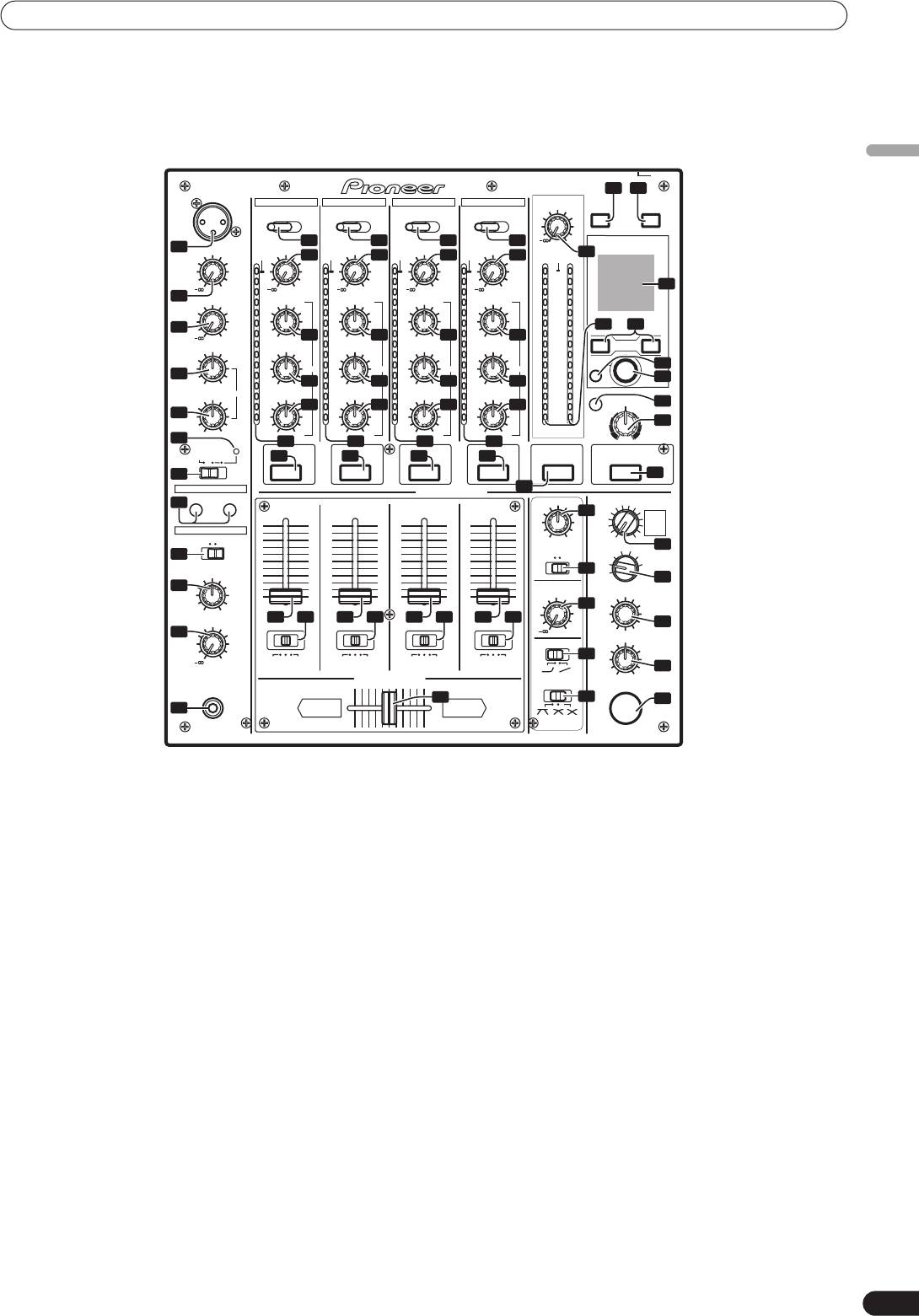
OPERATION PANEL
English
POWER
PROFESSIONAL MIXIER
DJM–700
33 34
MIC1
CH-1 CH-2 CH-3 CH-4
MASTER
MIDI
LEVEL
ON/OFF START/STOP
LINECD CD PHONO LINE PHONO LINE PHONO
8
9
10
10
0
BEAT EFFECTS
1
MIC1 LEVEL
TRIM
TRIM
TRIM
TRIM
OVER
11
OVER
11
OVER
11
OVER
11
23
OVER
10
10
10
10
10
0
+9
+9
+9
+9
44
7
7
7
7
7
2
MIC2 LEVEL
4
HI
4
HI
4
HI
4
HI
4
2
2
2
2
2
1
1
1
1
1
3
24 32
0
12
0
0
+6-26
12
0
12
0
0
+6-26
12
HI
–1
MID
–1
MID
–1
+6-26
+6-26
MID
–1
MID
–1
23
BEAT
–2
–2
–2
–2
–2
–3
–3
–3
–3
–3
EQ EQ EQ EQ
AUTO
35
4
–5
–5
–5
–5
–5
TAP
36
+12-12
–7
+6-26
13
–7
+6-26
13
–7
+6-26
13
–7
+6-26
13
–7
LOW
EQ
–10
LOW
–10
LOW
–10
LOW
–10
LOW
–10
FILTER
–15
14
–15
FREQUENCY
14
–15
14
–15
14
–15
37
5
–24
–24
–24
–24
–24
dB
dB
dB
dB
38
dBLR
+12-12
+6-26
+6-26
+6-26
+6-26
6
HPFLPF
15
15
15
15
MIC
TALK
OFF ON
OVER
16 16 16 16
1234
MASTER EFFECTS
7
16
FADER START
HEADPHONES CUE
16
CH-1 CH-2
17
BALANCE
REVERB
ROBOT
PHASER
CRUSH ROLL
25
FLANGER
ROLL
FILTER
REVERSE
10
10
10
10
TRANS
UP
HEADPHONES
9
9
9
9
ECHO
DOWN
MONO SPLIT STEREO
8
8
8
8
RL
DELAY
SND/RTN
7
7
7
7
4
MIC
39
28
6
6
6
6
MONO STEREO
3
5
5
5
5
CF.A
2
4
4
4
4
CF.B
26
MIXING
3
3
3
3
1
MASTER
2
2
2
2
40
29
1
1
1
1
BOOTH MONITOR
0
0
0
0
LEVEL
TIME
27
MASTERCUE
LEVEL
18 19 18 19
18 19 18 19
41
30
0
LEVEL/DEPTH
CH FADER
A THRU B
A THRU B A THRU B A THRU B
20
0
42
MIN
MAX
CROSS FADER ASSIGN
CROSS FADER
ON/OFF
PHONES
22
21
43
31
AB
1 Microphone 1 input jack (MIC 1)
TALK OVER:
Connect microphone with XLR-type plug.
Microphone sound is output; when sound is input to a connected
microphone, the TALK OVER function operates and all sound
2 Microphone 1 level control dial (MIC 1 LEVEL)
other than that from the microphone is attenuated by 20 dB.
Use to adjust the volume of microphone 1. (adjustable range –
∞
to
0 dB)
• When not using the TALK OVER function, it is recommended to
set the switch to the [
OFF
] or [
ON
] position.
3 Microphone 2 level control dial (MIC 2 LEVEL)
Use to adjust the volume of microphone 2. (adjustable range –
∞
to
8 Channel 1 input selector switch
0 dB)
CD:
Selects
CD
input (line level analog input).
4 Microphone equalizer high-range control dial (HI)
LINE:
Use to adjust the treble (high-range) frequencies of microphones 1
Use to select
LINE
input connectors.
and 2. (adjustable range –12 dB to +12 dB)
9 Channel 2 input selector switch
5 Microphone equalizer low-range control dial (LOW)
CD:
Use to adjust the bass (low-range) frequencies of microphones 1
Selects
CD
input (line level analog input).
and 2. (adjustable range –12 dB to +12 dB)
PHONO:
6 Microphone function indicator
Use to select
PHONO
input connectors (analog turntable input).
Lights when microphone is ON; flashes when
TALK OVER
is ON.
10 Channel 3, 4 input selector switch
7 Microphone function selector switch (MIC)
LINE:
OFF:
Selects
LINE
input (line level analog input).
No microphone sound is output.
PHONO:
ON:
Use to select
PHONO
input connectors (analog turntable input).
Microphone sound is output normally.
11 TRIM adjust dial
Use to adjust the input level for each channel. (adjustable range: –
∞
to +9 dB, mid-position is about 0 dB)
12 Channel equalizer high-range adjust dial (HI)
Use to adjust the treble (high-range) frequency sound for each
channel. (adjustable range: –26 dB to +6 dB)
9
En

01_DJM-700_En.book 10 ページ 2007年7月10日 火曜日 午後8時41分
NAMES AND FUNCTIONS OF PARTS
13 Channel equalizer mid-range adjust dial (MID)
21 Cross fader curve switch (CROSS FADER)
Use to adjust the mid-range frequency sound for each channel.
This switch allows the user to select from three types of cross fader
(adjustable range: –26 dB to +6 dB)
curve response.
14 Channel equalizer low-range adjust dial (LOW)
• At the left setting, the curve produces a rapid signal rise. (As
Use to adjust the bass (low-range) frequency sound for each
soon as the cross fader lever leaves the [
A
] side, the [
B
] channel
channel. (adjustable range: –26 dB to +6 dB)
sound is produced.)
15 Channel level indicator
• At the right setting, the curve operates to produce an even,
Displays the current level for each channel, with two-second peak
neutral rise throughout the cross fader’s movement.
hold.
• At the middle setting, an intermediate curve is produced,
16 HEADPHONES CUE buttons/indicators
midway between the two curves noted above.
These buttons are used to select from
1
to
4
,
MASTER
, or
22 Cross fader lever
EFFECTS
, to allow you to monitor the desired source through
Outputs sound assigned to [
A
] and [
B
] sides in accordance with
headphones. If multiple buttons are pressed simultaneously, the
setting of the
CROSS FADER ASSIGN
switch, and subject to the
selected audio sources are mixed. Press the button once more to
cross fader curve selected with the
CROSS FADER
curve switch.
cancel the selected source. Unselected buttons glow darkly, while
23 Master output level dial (MASTER LEVEL)
selected source buttons light brightly.
Use to adjust the master output level. (adjustable range: –
∞
to
17 Fader start button/indicator (FADER START CH-1, CH-2)
0 dB)
Enables the fader start/back cue function for the channel to which
The master output is the sum combination of the sound from
a DJ CD player is connected. The button lights when set to ON.
channels set to [
THRU
] with the
CROSS FADER ASSIGN
switch;
When enabled, the operation differs depending on the setting of
the signal passed through the cross fader; and the signals from
the
CROSS FADER ASSIGN
switch.
microphone 1 and microphone 2 (if the effect selector is set to
• When the
CROSS FADER ASSIGN
switch is set to the [
A
] or [
B
]
[
SND/RTN
], the
RETURN
input is also added).
position, fader start button operation is linked to the operation of
24 Master level indicator (MASTER L, R)
the cross fader (and unlinked to channel fader).
These segment indicators display the output level from L and R
• When the
CROSS FADER ASSIGN
switch is set to the [
THRU
]
channels. The indicators have a two-second peak hold.
position, fader start button operation is linked to the operation of
25 Master balance dial (BALANCE)
the channel fader (and unlinked to cross fader).
Use to adjust the L/R channel balance for master output, booth
18 Channel fader lever
monitor output, recording output, and digital output.
Use to adjust sound volumes for each channel. (adjustable range:
26 Master output MONO/STEREO selector switch
–
∞
to 0 dB)
When set to the [
MONO
] position, master output, booth monitor
Output is in accordance with the channel fader curve selected
output, recording output, digital output are all produced in L+R
with the
CH FADER
curve switch.
monaural.
19 CROSS FADER ASSIGN switch
27 BOOTH MONITOR LEVEL control dial
This switch assigns each channel’s output to either right or left
This dial is used to adjust the booth monitor output volume.
side of the cross fader (if multiple channels are assigned to the
The volume can be adjusted independently of the master output
same side, the result will be the combined sum of the channels).
level. (adjustable range: –
∞
to 0 dB)
A:
28 Headphones output switch (MONO SPLIT/STEREO)
The selected channel is assigned to the cross fader’s A (left) side.
MONO SPLIT:
THRU:
When
HEADPHONES CUE
(
1
,
2
,
3
,
4
or
EFFECTS
) button is
The channel fader’s output is sent as is to the master output,
selected, the selected audio is output to the L channel. When
without being passed through the cross fader.
HEADPHONES CUE
(
MASTER
) button is selected, the master
B:
audio is output from the R channel.
The selected channel is assigned to the cross fader’s B (right) side.
STEREO:
20 Channel fader curve switch (CH FADER)
The audio source selected with the
HEADPHONES CUE
button is
This switch allows the user to select from two types of channel
output in stereo.
fader curve response. This setting is applied equally to channels
29 Headphones mixing dial (MIXING)
1 to 4.
When rotated clockwise (toward [
MASTER
]), the master output
• At the left setting, the curve operates to produce a rapid rise as
audio is produced at the headphones (only when [
MASTER
] has
the channel fader approaches its distant position.
been selected with the
HEADPHONES CUE
button); when rotated
• At the right setting, the curve operates to produce an even,
counterclockwise (toward [
CUE
]), the headphones output
neutral rise throughout the channel fader’s movement.
becomes the mixture of the effect monitor and the channel
selected with the
HEADPHONES CUE
button.
In the middle position, the audio from [
MASTER
] and [
CUE
] will be
output.
30 Headphones level adjust dial (LEVEL)
Adjusts the output level of the headphones jack. (adjustable range:
–
∞
to 0 dB)
10
En
01_DJM-700_En.book 11 ページ 2007年7月10日 火曜日 午後8時41分
NAMES AND FUNCTIONS OF PARTS
31 Headphones jack (PHONES)
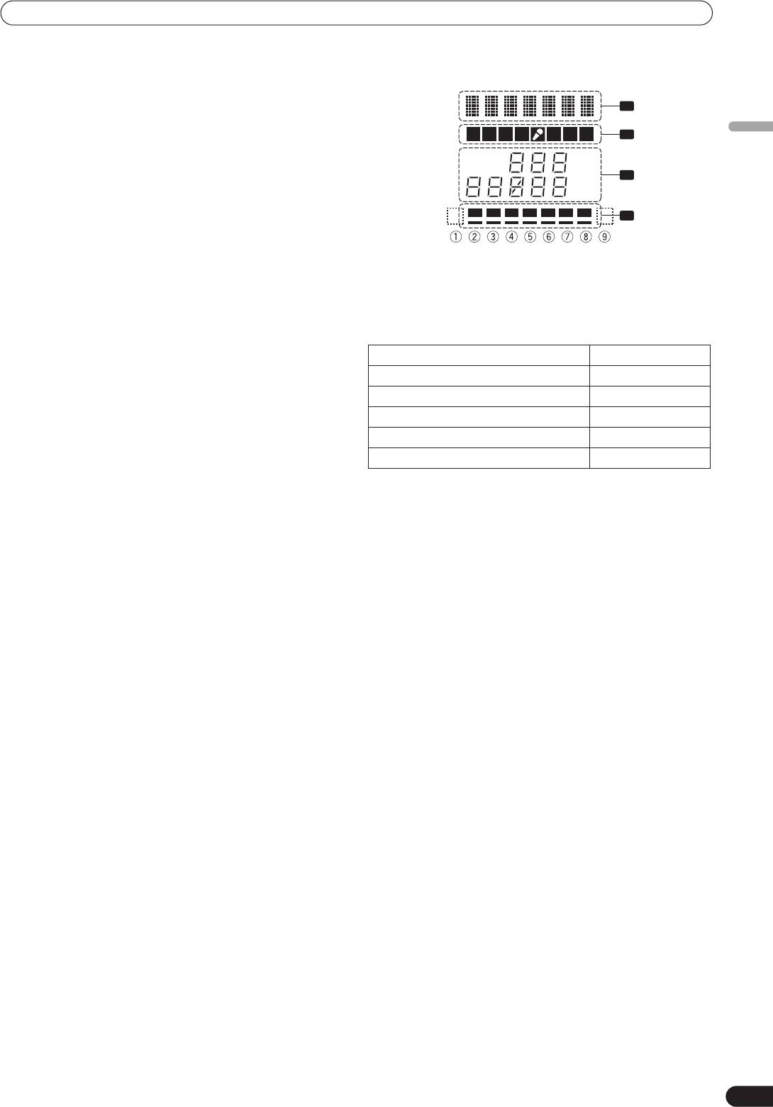
DISPLAY SECTION
Connect to headphones equipped with phone-type jack.
32 Beat select buttons (
BEAT
)
1
(Beat up):Doubles the calculated BPM.
(Beat down):Halves the calculated BPM.
123 4
A B M
2
English
(P. 18)
• Some effects can be set for
“3/4”
.
AUTO
MIDI
TAP
BPM
With some effects, these are used for functions other than setting
3
%
the beat.
mS
33 MIDI ON/OFF button
4
Sets MIDI output function (not including timing lock) to ON/OFF.
When power is first turned ON, automatically defaults to OFF.
34 MIDI start/stop button (MIDI START/STOP)
Outputs START/STOP signal for MIDI control function (see P. 21).
1 Effects display section
When this control is enabled, the [
MIDI START (STOP)
] message
Text display (7 characters) displays effect name as shown in
appears for two seconds on the display.
accompanying table. Also, when one of the change operations is
performed as noted in the table, the corresponding characters are
MIDI SNAP SHOT:
displayed for two seconds, after which the display returns to the
When the
MIDI START/STOP
button is held depressed, a snapshot
original effect name.
is sent to the external MIDI component.
35 BPM measuring mode button (AUTO)
Switching Operation Display
Switches between the BPM measuring modes AUTO and TAP.
When [
AUTO
] indicator on the display is lighted, the BPM will be
At MIDI start START
measured automatically.
At MIDI stop STOP
36
TAP
button
MIDI snapshot SNAP
The BPM is calculated from the intervals at which the
TAP
button
is struck. If the
TAP
button is pressed in the AUTO mode, the mode
When MIDI output function is ON MIDI On
automatically switches to the TAP mode (manual input).
When MIDI output function is OFF MIDIOff
37 MANUAL/EFFECT Frequency filter button
Use to switch between manual filter and effect frequency filter.
2 Channel select display section
When power is first turned ON, defaults to effect frequency filter
Lights position selected by effect channel selector.
and the button indicator lights. When manual filter is selected, the
3 Parameter display section
button indicator does not light.
AUTO/TAP:
38 Manual filter adjust dial (FREQUENCY)
[
AUTO
] lights when the BPM measuring mode is set to AUTO, and
Use to adjust the cutoff frequency of the selected filter.
[
TAP
] lights when the BPM measuring mode is set to manual
39 Effect selector (DELAY, ECHO, TRANS, FILTER, FLANGER,
(TAP).
PHASER, REVERB, ROBOT (ROBOT VOCODER), CRUSH, ROLL,
BPM counter display
(3 digits)
:
REVERSE (REVERSE ROLL), UP (UP ROLL), DOWN (DOWN
In AUTO mode, displays the automatically detected BPM value. If
ROLL), SND/RTN (SEND/RETURN))
the BPM count cannot be detected automatically, the display will
Use to select desired type of effect (P. 16).
flash at the previously detected value. In manual (TAP) mode,
When using an external effector connected to the
SEND
and
displays the BPM value designated by TAP input, etc.
RETURN
connectors, set to the [
SND/RTN
] position.
BPM:
40 Effect channel selector (1, 2, 3, 4, MIC, CF.A, CF.B, MASTER)
Lights constantly.
Use to select the channel to which effects are applied (P. 18).
MIDI:
When [
MIC
] is selected, effects are applied to both microphone 1
Indicates status of MIDI output function ON/OFF.
and microphone 2.
• Lights when MIDI output function is ON.
41 Effect parameter 1 dial [TIME (PARAMETER 1)]
• Not lighted when MIDI output function is OFF.
Adjusts time parameter for selected effect (P. 18, 20) (With some
Parameter 1 display
(5 digits)
:
effects, this is used for adjustments other than time parameters.)
Displays parameters designated for each effect. When the beat
• If the
TIME
dial is rotated while depressing the
TAP
button,
select buttons (
BEAT
,
) are pressed, the corresponding beat
direct BPM can be set manually.
multiple change is displayed for two seconds. If the beat select
• If the
TIME
dial is rotated while holding the
TAP
button and
buttons (
BEAT
,
) are used to designate a value outside the
AUTO/TAP
buttons depressed, the BPM can be set in 0.1 units.
parameter range, the current number will flash but will not
change.
42 Effect parameter 2 dial [LEVEL/DEPTH (PARAMETER 2)]
Unit Display (%/ms):
Adjusts quantitative parameters for selected effect (P. 18, 20).
Lights in accordance with the unit used for each effect.
43 Effect button/indicator (ON/OFF)
Sets selected effect ON/OFF (P. 18). When power is first turned
ON, defaults to effect OFF. When set to effect OFF, the button
indicator lights. When effects are enabled (ON), the button
flashes.
44 Display
See the following section for details.
11
En
01_DJM-700_En.book 12 ページ 2007年7月10日 火曜日 午後8時41分
NAMES AND FUNCTIONS OF PARTS
4 Beat display section
indicator flashes. Although the display includes seven actual
Displays the location of parameter 1 relative to BPM (1/1 beat). The
indicators, the values of the two ends can also be considered to
lower row is lighted constantly. When the parameter 1 location
represent indicators, with the result that nine positions can be
approaches a threshold value, the corresponding indicator is
logically assumed. When the values are at the two ends, no
lighted. When the parameter 1 is between threshold values, the
indicators light.
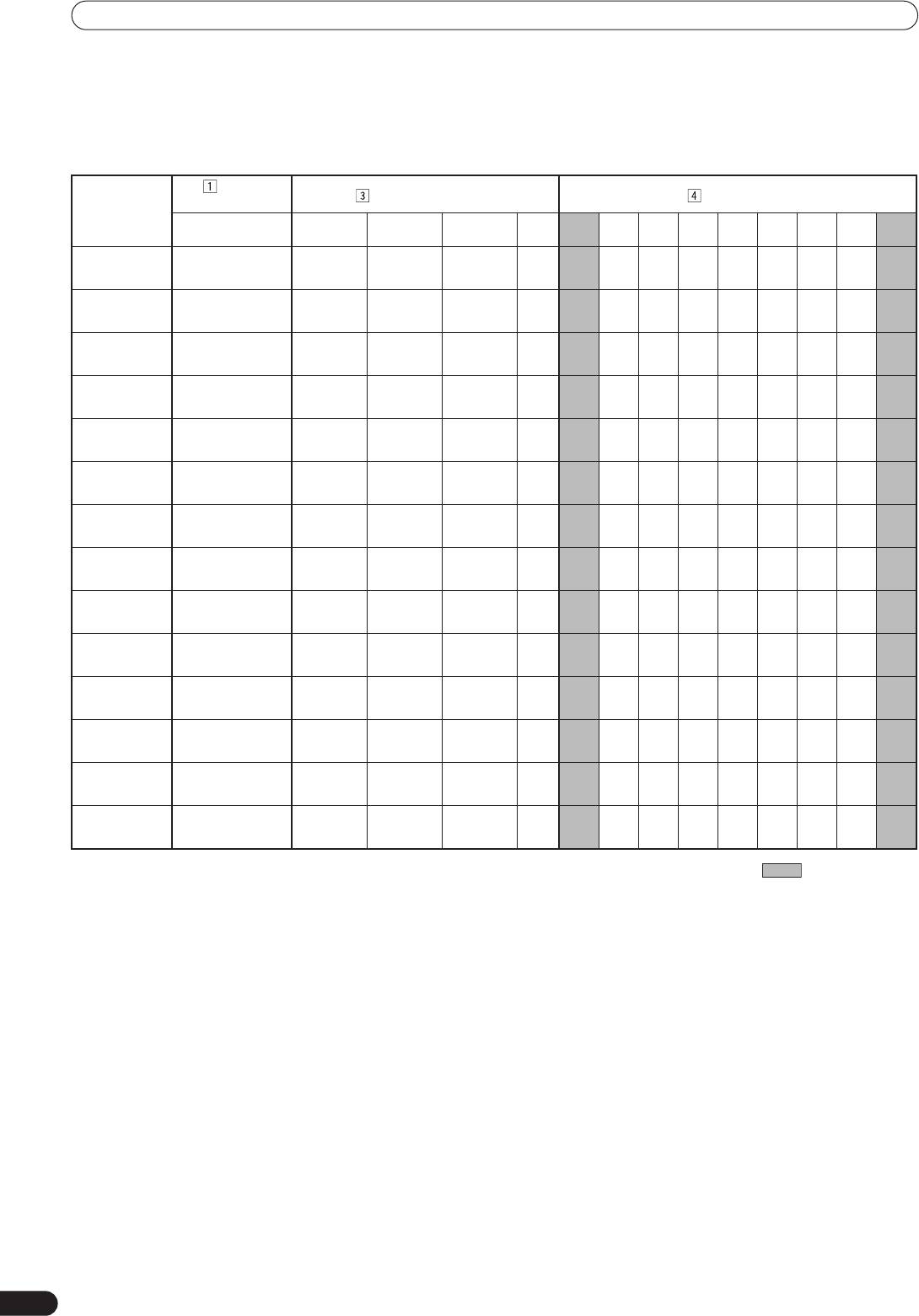
Effect
Parameter display Beat display
Effect
display
selector
Minimum
Maximum
Effect name
Default Unit
➀➁➂➃➄➅➆➇
➈
value
value
DELAY DELAY 1 4 000 500 ms 1/8 1/4 1/2 3/4 1/1 2/1 4/1 8/1 16/1
ECHO ECHO 1 4 000 500 ms
1/8 1/4 1/2 3/4 1/1 2/1 4/1 8/1 16/1
TRANS TRANS 10 16 000 500 ms
1/16 1/8 1/4 1/2 1/1 2/1 4/1 8/1 16/1
FILTER FILTER 10 32 000 2 000 ms
1/4 1/2 1/1 2/1 4/1 8/1 16/1 32/1 64/1
FLANGER FLANGER 10 32 000 2 000 ms
1/4 1/2 1/1 2/1 4/1 8/1 16/1 32/1 64/1
PHASER PHASER 10 32 000 2 000 ms
1/4 1/2 1/1 2/1 4/1 8/1 16/1 32/1 64/1
REVERB REVERB 1 100 50 %
10 20 30 40 50 60 70 80 90
ROBOT ROBOT –100 100 0 %
—
–100
–66 –50 0 26 50 100 —
CRUSH CRUSH 10 32 000 2 000 ms
1/4 1/2 1/1 2/1 4/1 8/1 16/1 32/1 64/1
ROLL ROLL 10 4 000 500 ms
1/16 1/8 1/4 1/2 1/1 2/1 4/1 8/1 16/1
REV ROLL REVROLL 10 4 000 500 ms
1/16 1/8 1/4 1/2 1/1 2/1 4/1 8/1 16/1
UP ROLL UP ROLL 10 4 000 500 ms
1/16 1/8 1/4 1/2 1/1 2/1 4/1 8/1 16/1
DOWN ROLL DWNROLL 10 4 000 500 ms
1/16 1/8 1/4 1/2 1/1 2/1 4/1 8/1 16/1
SND/RTN SND/RTN
Shaded items are not displayed.
12
En
Оглавление
- Contents
- CONFIRM FEATURES ACCESSORIES
- CONNECTIONS
- NAMES AND FUNCTIONS OF PARTS
- MIXER OPERATIONS
- EFFECT FUNCTIONS
- MIDI SETTINGS
- TROUBLESHOOTING
- SPECIFICATIONS
- Table des matières
- VÉRIFICATION DES CARACTÉRISTIQUES ACCESSOIRES
- BRANCHEMENTS
- NOMS ET FONCTIONS DES ORGANES
- UTILISATION DU MIXEUR
- FONCTIONS DES EFFETS
- RÉGLAGES MIDI
- GUIDE DE DÉPANNAGE
- FICHE TECHNIQUE
- INHALTSVERZEICHNIS
- ÜBERPRÜFEN DES
- ANSCHLÜSSE
- BEZEICHNUNG UND FUNKTION DER BEDIENELEMENTE
- BEDIENUNG DES MISCHPULTS
- EFFEKTFUNKTIONEN
- MIDI-EINSTELLUNGEN
- STÖRUNGSBESEITIGUNG
- TECHNISCHE DATEN
- INDICE
- CONFERMA DEGLI CARATTERISTICHE ACCESSORI
- COLLEGAMENTI
- NOME DELLE VARIE PARTI E LORO FUNZIONE
- OPERAZIONI COL MIXER
- FUNZIONI DI EFFETTO
- IMPOSTAZIONI MIDI
- DIAGNOSTICA
- CARATTERISTICHE TECNICHE
- INHOUDSOPGAVE
- CONTROLEER DE KENMERKEN ACCESSOIRES
- AANSLUITINGEN
- BENAMING EN FUNCTIE VAN DE BEDIENINGSORGANEN
- BEDIENING VAN HET MENGPANEEL
- EFFECTFUNCTIES
- MIDI-INSTELLINGEN
- VERHELPEN VAN STORINGEN
- TECHNISCHE GEGEVENS
- ÍNDICE
- CONFIRMACIÓN DE CARACTERÍSTICAS LOS ACCESORIOS
- CONEXIONES
- NOMENCLATURA Y FUNCIONES DE LOS CONTROLES
- OPERACIONES DE LA CONSOLA DE MEZCLA
- FUNCIONES DE LOS EFECTOS
- AJUSTES DE MIDI
- SOLUCIÓN DE PROBLEMAS
- ESPECIFICACIONES
- СОДЕРЖАНИЕ
- ПРОВЕРКА НАЛИЧИЯ ФУНКЦИОНАЛЬНЫЕ ПРИНАДЛЕЖНОСТЕЙ ОСОБЕННОСТИ
- ПОДКЛЮЧЕНИЕ ПУЛЬТА
- ЭЛЕМЕНТЫ ПУЛЬТА И ИХ ФУНКЦИИ
- ОПЕРАЦИИ С МИКШЕРОМ
- ЭФФЕКТЫ
- НАСТРОЙКА MIDI-ИНТЕРФЕЙСА
- УСТРАНЕНИЕ НЕПОЛАДОК
- ТЕХНИЧЕСКИЕ ХАРАКТЕРИСТИКИ
- BLOCK DIAGRAM / SCHÉMA DE PRINCIPE / BLOCKSCHALTBILD / DIAGRAMMA A BLOCCHI / BLOKSCHEMA / DIAGRAMA EN BLOQUES / БЛОК-СХЕМА ПУЛЬТА


