Pioneer DJM-700-K: CONNECTIONS
CONNECTIONS: Pioneer DJM-700-K
01_DJM-700_En.book 5 ページ 2007年7月10日 火曜日 午後8時41分
CONNECTIONS
CONNECTIONS
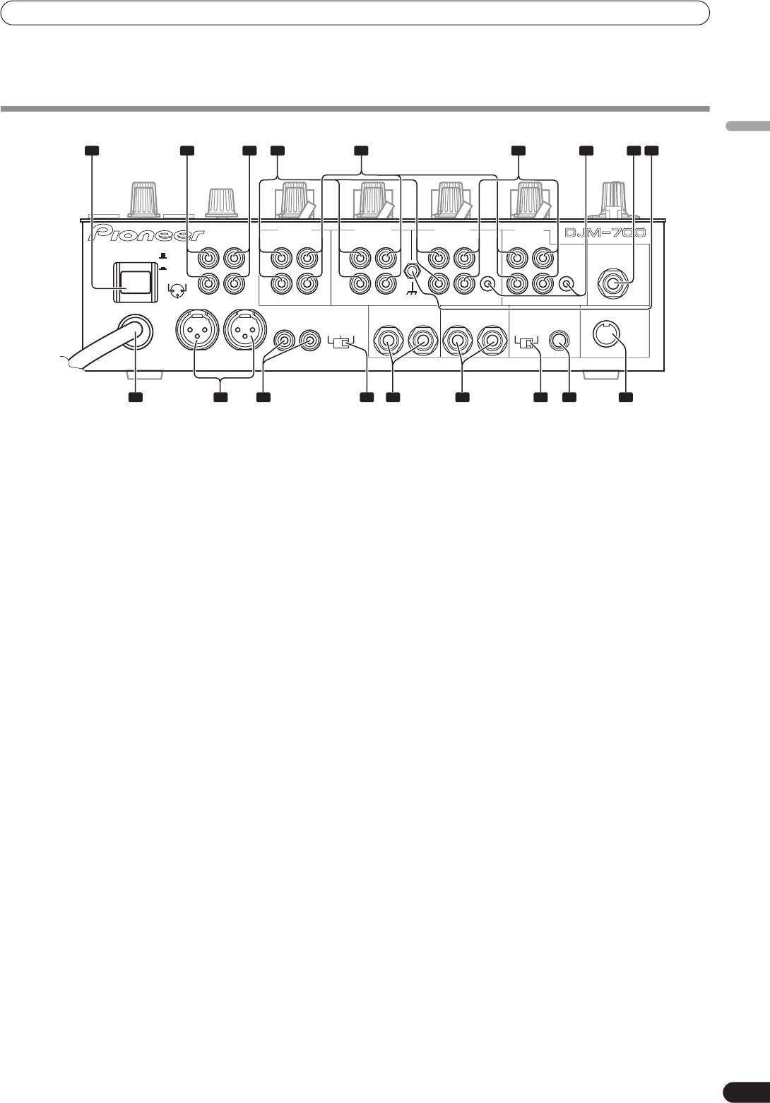
CONNECTION PANEL
English
1 2 3 4 7 8 9
5 6
CH-4 CH-3 CH-2 CH-1
BOOTH REC
PHONO LINE
PHONO LINE PHONO
CD
LINE
CD
L
L
L
L
L
POWER
OFF
MIC 2
ON
CONTROL
CONTROL
1 GND
2 HOT
R
R
R
R
R
3 COLD
SIGNAL GND
RL
MASTER1
MASTER2
MASTER
SEND
RETURN
DIGITAL OUT
MIDI OUT
RL
ATT.
RL
(MONO)
RL
(MONO)
fs(Hz)
-6dB -3dB 0dB
48k 96k
101112151718 1316 14
1 POWER switch
11 DIGITAL OUT connector
2 BOOTH monitor output connectors
RCA type digital coaxial output connector.
RCA-type booth monitor output jack.
Master audio digital output.
The sound level from these connectors is controlled independently
12 Sampling frequency selector switch (fs 48 k/96 k)
by the
BOOTH MONITOR LEVEL
dial, regardless of the position of
Use to set the sampling frequency of the digital output to 96 kHz/
the
MASTER LEVEL
dial.
24-bit format or 48 kHz/24-bit format.
3 Recording output connectors (REC)
• Turn power off before changing this switch position.
RCA type output connectors for recording.
13 RETURN connectors
4 PHONO input connectors
Ø6.3 mm phone-type input connectors.
RCA type phono level (MM cartridge) input connectors.
Use to connect to the output connectors of external effectors or
Do not use for inputting line level signals.
similar components.
5 LINE input connectors
When the L channel only is connected, the L channel input is
simultaneously input to the R channel.
RCA type line level input connectors.
Use to connect a cassette deck or other line level output
14 SEND output connectors
component.
Ø6.3 mm phone-type output connectors.
6CD input connectors
Use to connect to the input connectors of external effectors or
other similar components. When the L channel only is connected,
RCA type line level input connectors.
a L+R monaural signal is output.
Use to connect a DJ CD player or other line level output
component.
15 Master output attenuator switch (MASTER ATT)
7 CONTROL connectors
Use to attenuate the level of the master 1 and master 2 outputs.
Attenuation can be set to 0 dB, –3 dB, or –6 dB.
Ø3.5 mm mini-connector. Use to connect to the control connector
of a Pioneer DJ CD player.
16 MASTER 2 output connectors
When the connectors are connected, the DJM-700-S/DJM-700-K’s
RCA type unbalanced output.
fader can be used to perform start/stop on the DJ CD player.
17 MASTER 1 output connectors
8 Two microphone input jacks (MIC 2)
XLR type (male) balanced output.
Connect microphones equipped with phone-type plugs.
• When using a cord with RCA-type plug, users are recommended
9 Signal grounding terminals (SIGNAL GND)
to connect the plug directly to the
MASTER 2
connectors
Reduces noise when connecting an analog turntable.
without using an XLR/RCA converter plug.
10 MIDI OUT connector
18 Power cord
DIN type output connector.
Connect to ordinary AC outlet.
Use to connect to other MIDI component (see P. 21).
5
En
01_DJM-700_En.book 6 ページ 2007年7月10日 火曜日 午後8時41分
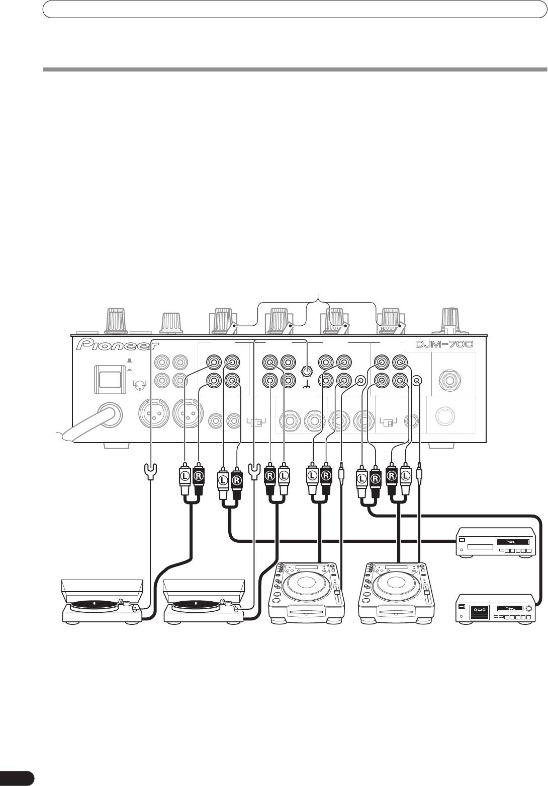
CONNECTIONS
Always turn off the power switch and disconnect the power plug from its outlet when making or changing connections.
CONNECTING INPUTS
Pioneer DJ CD players
Connect the ground wire from an analog turntable to the
The audio output connectors of a DJ-type CD player can be
SIGNAL GND
terminal of the DJM-700-S/DJM-700-K.
connected to the
CD
input connectors (channel 1 or 2), or to the
• Note that no
PHONO
input connector is provided for channel 1.
LINE
input connectors (channel 1) of the DJM-700-S/DJM-700-K.
Connect the control cord to the
CONTROL
jack, and set the input
Connecting other line level output devices
selector switch to [
CD
] or [
LINE
].
To use a cassette deck or ordinary CD player, connect its audio
output connectors to one of the DJM-700-S/DJM-700-K’s
LINE
Analog turntable
input connectors (channel 1, 3, or 4) or to the
CD
input connectors
To connect an analog turntable, connect the turntable’s audio
(channel 1 or 2), and set the input selector switch to [
LINE
].
output cable to one of the channel 2 to 4
PHONO
input
connectors. Set the corresponding channel’s input selector switch
to [
PHONO
]. The DJM-700-S/DJM-700-K’s
PHONO
inputs support
MM cartridges.
Input selector switch
CH-4 CH-3 CH-2 CH-1
BOOTH REC
PHONO LINE
PHONO LINE PHONO
CD
LINE
CD
L
L
L
L
L
POWER
OFF
MIC 2
ON
CONTROL
CONTROL
1 GND
2 HOT
R
R
R
R
R
3 COLD
RL
MASTER1
SIGNAL GND
MASTER2
MASTER
SEND
RETURN
DIGITAL OUT
MIDI OUT
RL
ATT.
RL
(MONO)
RL
(MONO)
fs(Hz)
-6dB -3dB 0dB
48k 96k
CD player, etc.
Analog turntable Analog turntable DJ CD player DJ CD player Cassette deck, etc.
6
En
01_DJM-700_En.book 7 ページ 2007年7月10日 火曜日 午後8時41分
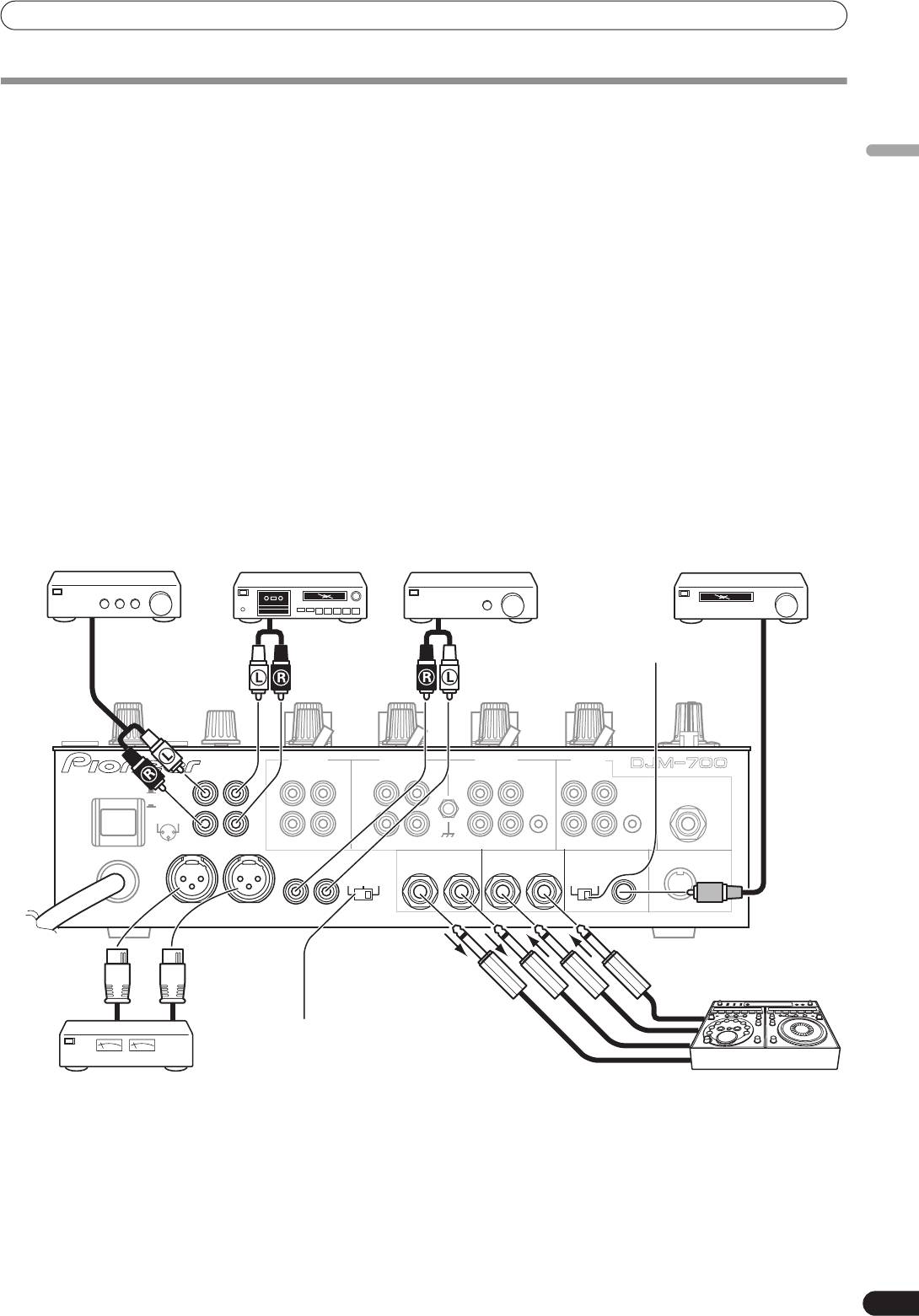
CONNECTIONS
CONNECTING EXTERNAL EFFECTORS, OUTPUT CONNECTORS
Master output
Digital output
This unit is furnished with balanced output
MASTER 1
(supporting
This is a coaxial digital output connector, supporting RCA plugs.
English
XLR plugs), and unbalanced output
MASTER 2
(supporting RCA
The sampling frequency can be set to 96 kHz/24-bit format or
plugs).
48 kHz/24-bit format to match the connected device.
Using the
MASTER ATT
switch, adjust the output level to match
• Turn power off before changing this switch position.
the input sensitivity of the power amplifier used.
If the operating panel’s
MONO/STEREO
switch is set to [
MONO
],
External effector
the master output will be a monaural combination of L+R
Use a cable with Ø6.3 mm phone plugs to connect the DJ mixer’s
channels.
SEND
connectors to the effector’s input connectors.
When using an effector with monaural inputs, connect only to the
Booth monitor output
DJ mixer’s L channel output. In this way, the mixed L+R audio
Unbalanced output supporting RCA-type plug. The sound volume
signal will be sent to the effector. In the same way, use a cable with
for this output is controlled by the
BOOTH MONITOR LEVEL
dial,
Ø6.3 mm phone plugs to connect the DJ mixer’s
RETURN
independently of the master output level setting.
connectors to the output connectors of the effector.
If the effector has only monaural output, connect to the DJ mixer’s
Recording output
L channel input only. The signal from the effector will be input to
These are output connectors for recording, supporting RCA plugs.
both L and R channels.
When using an external effector, set the effect selector to [
SND/
RTN
].
Cassette deck
Power amplifier
Digital input AV amplifier
Power amplifier
(analog input
(RCA plug input
(digital input
(for booth monitor)
recording device)
connectors)
recording device)
Sampling frequency
selector switch
CH-4 CH-3 CH-2 CH-1
BOOTH REC
PHONO LINE
PHONO LINE PHONO
CD
LINE
CD
L
L
L
L
L
POWER
OFF
MIC 2
ON
CONTROL
CONTROL
1 GND
2 HOT
R
R
R
R
R
3 COLD
SIGNAL GND
RL
MASTER1
MASTER2
MASTER
SEND
RETURN
DIGITAL OUT
MIDI OUT
RL
ATT.
RL
(MONO)
RL
(MONO)
fs(Hz)
-6dB -3dB 0dB
48k 96k
MASTER ATT switch
Power amplifier
External effector
(XLR plug input connectors)
7
En
CONNECTIONS
ABOUT MIDI CONNECTORS
See P. 21 regarding the functions of MIDI connectors.
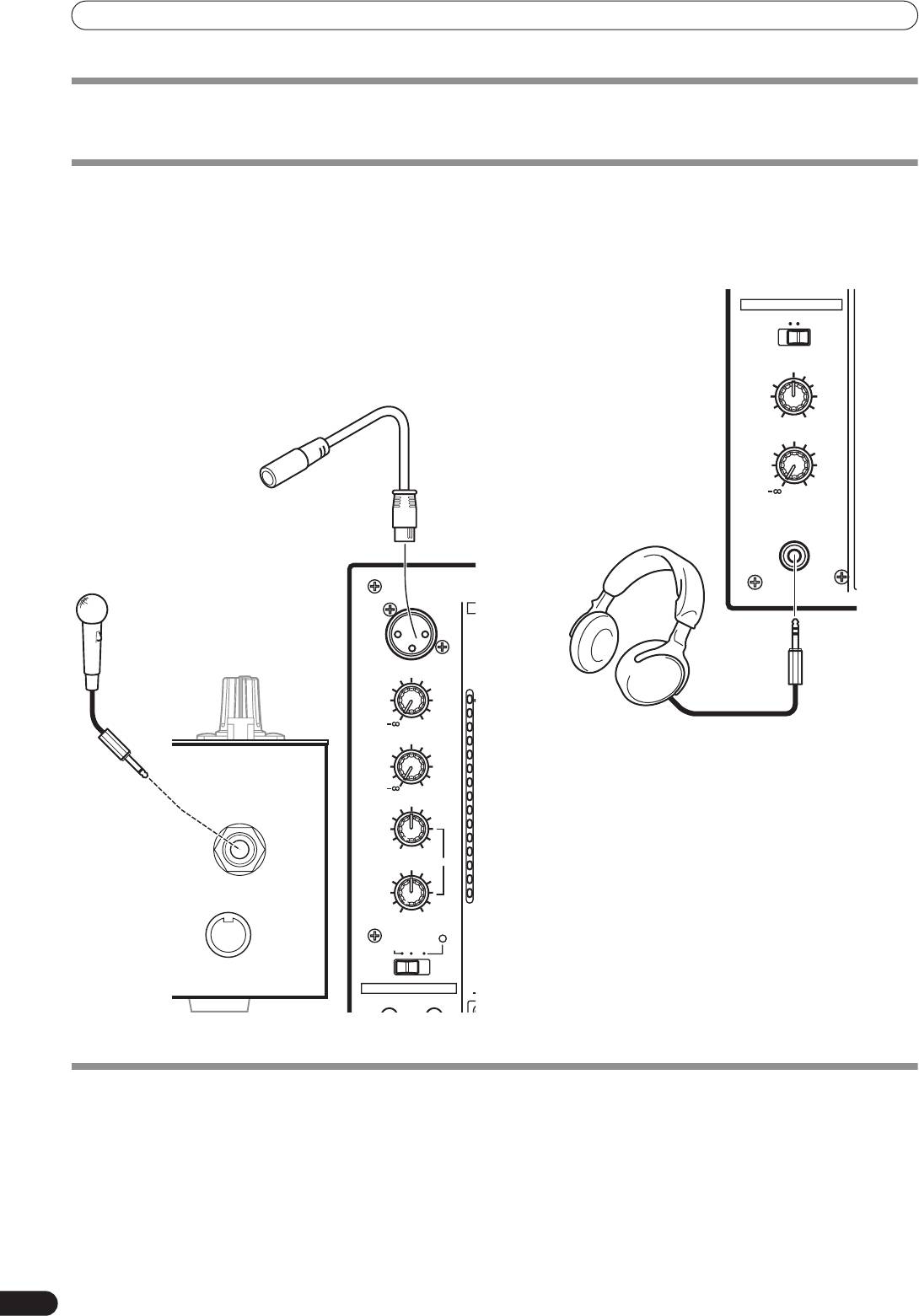
CONNECTING MICROPHONE AND HEADPHONES
Microphone
Headphones
A microphone with XLR-type plug can be connected to the
MIC 1
The
PHONES
jack on the upper surface of the operating panel can
connector on the Operation Panel (upper) .
be used to connect headphones with a Ø6.3 mm stereo phone
The
MIC 2
jack on the connection panel can be used to connect a
plug.
microphone with Ø6.3 mm phone plugs.
• When using a microphone, set the operating panel’s
MIC
switch
to [
ON
] or [
TALK OVER
], and adjust the
LEVEL
dial as
necessary.
When not using a microphone, it is recommended to set the
MIC
switch to [
OFF
] and rotate the
LEVEL
dial fully
counterclockwise to the [–
∞
] side.
MIC 2
MIDI OUT
CONNECTING THE POWER CORD
Connect the power cord last.
• After completing all other connections, connect the power plug to an ordinary AC outlet.
8
En
d
OV
1
7
4
2
1
0
–
–
–
–
–
–
–
–
01_DJM-700_En.book 8 ページ 2007年7月10日 火曜日 午後8時41分
HEADPHONES
MONO SPLIT STEREO
MIXING
MASTERCUE
Microphone 1
LEVEL
0
Headphones
PHONES
MIC1
Microphone 2
MIC1 LEVEL
0
MIC2 LEVEL
0
HI
+12-12
LOW
EQ
+12-12
MIC
TALK
OFF ON
OVER
FADER START
CH-1 CH-2
Оглавление
- Contents
- CONFIRM FEATURES ACCESSORIES
- CONNECTIONS
- NAMES AND FUNCTIONS OF PARTS
- MIXER OPERATIONS
- EFFECT FUNCTIONS
- MIDI SETTINGS
- TROUBLESHOOTING
- SPECIFICATIONS
- Table des matières
- VÉRIFICATION DES CARACTÉRISTIQUES ACCESSOIRES
- BRANCHEMENTS
- NOMS ET FONCTIONS DES ORGANES
- UTILISATION DU MIXEUR
- FONCTIONS DES EFFETS
- RÉGLAGES MIDI
- GUIDE DE DÉPANNAGE
- FICHE TECHNIQUE
- INHALTSVERZEICHNIS
- ÜBERPRÜFEN DES
- ANSCHLÜSSE
- BEZEICHNUNG UND FUNKTION DER BEDIENELEMENTE
- BEDIENUNG DES MISCHPULTS
- EFFEKTFUNKTIONEN
- MIDI-EINSTELLUNGEN
- STÖRUNGSBESEITIGUNG
- TECHNISCHE DATEN
- INDICE
- CONFERMA DEGLI CARATTERISTICHE ACCESSORI
- COLLEGAMENTI
- NOME DELLE VARIE PARTI E LORO FUNZIONE
- OPERAZIONI COL MIXER
- FUNZIONI DI EFFETTO
- IMPOSTAZIONI MIDI
- DIAGNOSTICA
- CARATTERISTICHE TECNICHE
- INHOUDSOPGAVE
- CONTROLEER DE KENMERKEN ACCESSOIRES
- AANSLUITINGEN
- BENAMING EN FUNCTIE VAN DE BEDIENINGSORGANEN
- BEDIENING VAN HET MENGPANEEL
- EFFECTFUNCTIES
- MIDI-INSTELLINGEN
- VERHELPEN VAN STORINGEN
- TECHNISCHE GEGEVENS
- ÍNDICE
- CONFIRMACIÓN DE CARACTERÍSTICAS LOS ACCESORIOS
- CONEXIONES
- NOMENCLATURA Y FUNCIONES DE LOS CONTROLES
- OPERACIONES DE LA CONSOLA DE MEZCLA
- FUNCIONES DE LOS EFECTOS
- AJUSTES DE MIDI
- SOLUCIÓN DE PROBLEMAS
- ESPECIFICACIONES
- СОДЕРЖАНИЕ
- ПРОВЕРКА НАЛИЧИЯ ФУНКЦИОНАЛЬНЫЕ ПРИНАДЛЕЖНОСТЕЙ ОСОБЕННОСТИ
- ПОДКЛЮЧЕНИЕ ПУЛЬТА
- ЭЛЕМЕНТЫ ПУЛЬТА И ИХ ФУНКЦИИ
- ОПЕРАЦИИ С МИКШЕРОМ
- ЭФФЕКТЫ
- НАСТРОЙКА MIDI-ИНТЕРФЕЙСА
- УСТРАНЕНИЕ НЕПОЛАДОК
- ТЕХНИЧЕСКИЕ ХАРАКТЕРИСТИКИ
- BLOCK DIAGRAM / SCHÉMA DE PRINCIPE / BLOCKSCHALTBILD / DIAGRAMMA A BLOCCHI / BLOKSCHEMA / DIAGRAMA EN BLOQUES / БЛОК-СХЕМА ПУЛЬТА


