AEG EWH 120 Trend: INSTALLATION
INSTALLATION: AEG EWH 120 Trend
Operation - Installation
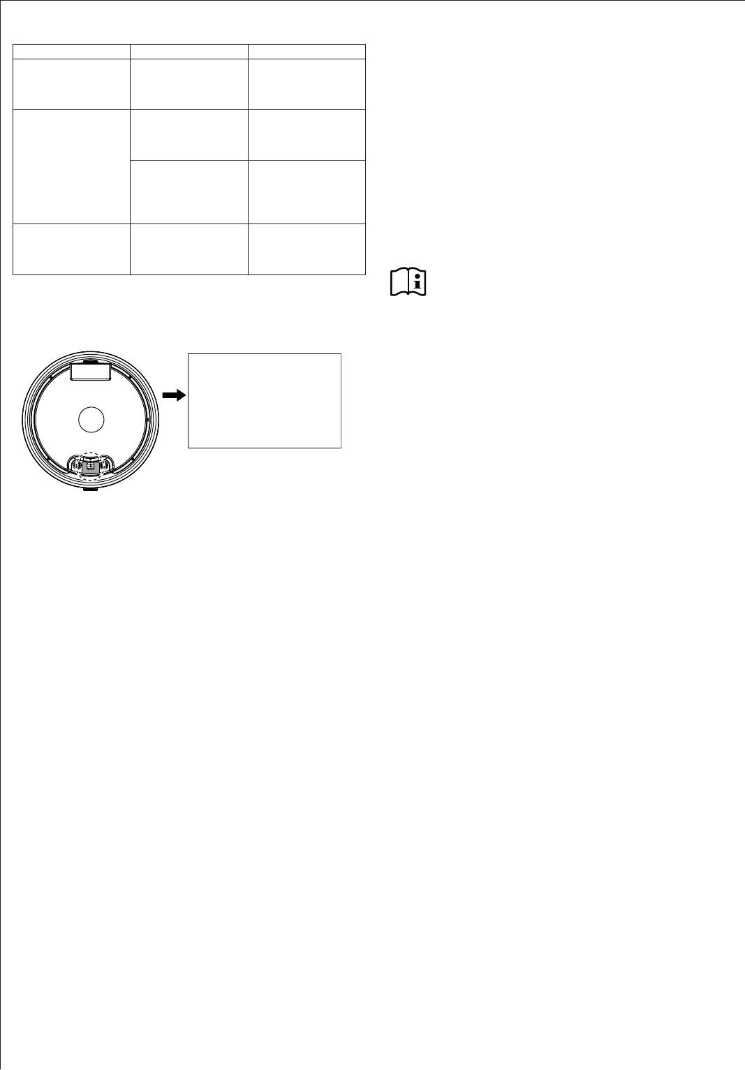
6. Troubleshooting
Problem
INSTALLATION
The water does not
There is no power. Check the fuses/
heat up and the ON/
MCBs in your fuse
OFF indicator does
box.
not illuminate.
The water does not
The temperature is set
Select a higher tem-
7.
heat up sufficiently
too low.
perature.
and the ON/OFF indi-
commissioning, maintenance and repair of the appliance.
cator illuminates.
The appliance heats,
Wait until the ON/OFF
7.1
for example, after
indicator goes out.
large amounts of
We guarantee trouble-free function and operational relia-
DHW have been
bility only if original accessories and spare parts intended
drawn.
for the appliance are used.
The flow rate is low.
The aerator in the
Clean and/or descale
tap or shower head is
the aerator or shower
7.2
scaled up or contam-
head.
inated.
Note
-
-
tractor. To facilitate and speed up your enquiry, please
provide the numbers from the type plate (000000 and
0000-000000):
8.
8.1
E-NO.: 000000
F-NO.: 0000-000000
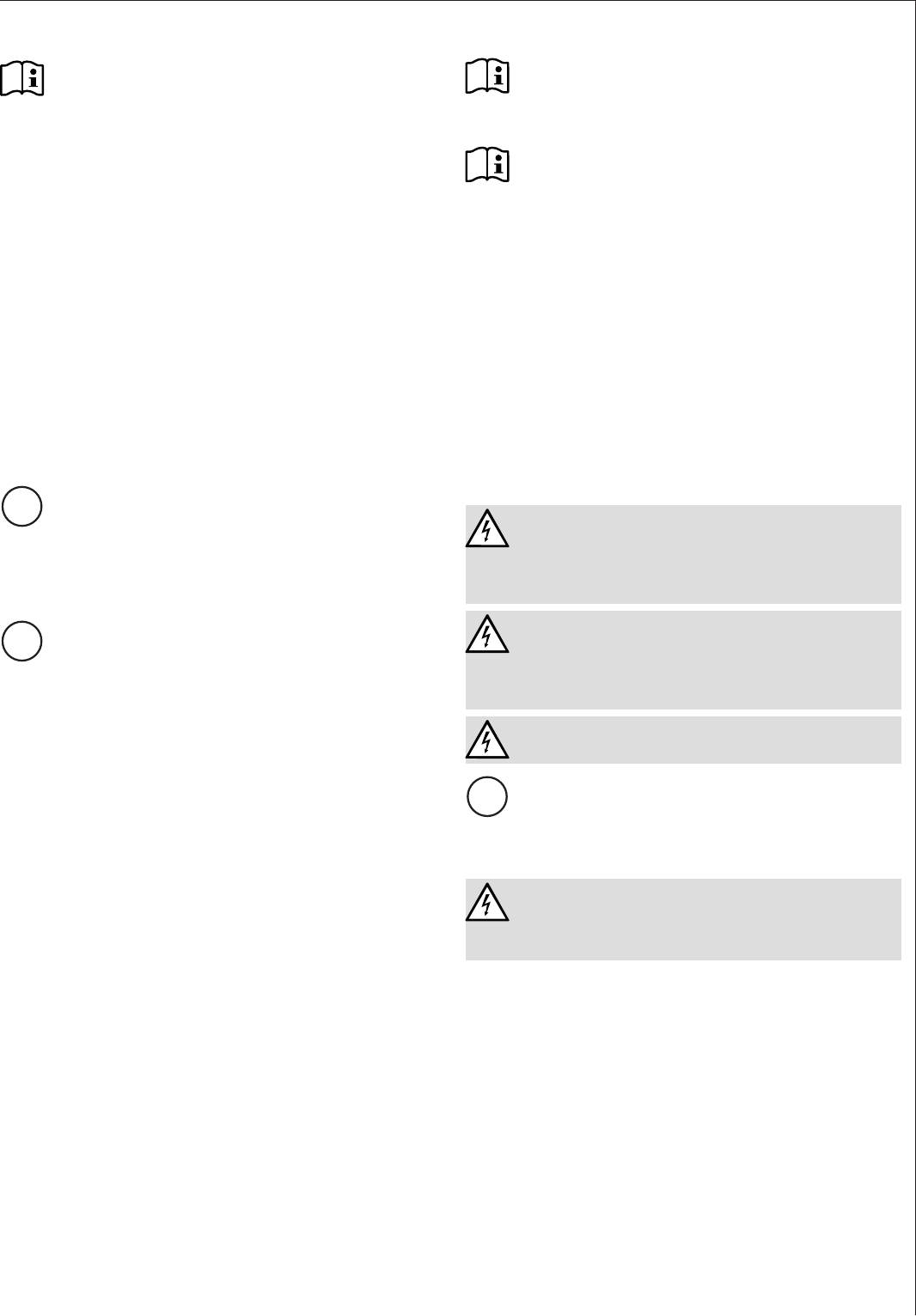
The following are delivered with the appliance:
Safety valve
The safety valve supplied must not be used in
Belgium. For use here please use standard safety
valves (see also pricelist).
Temperature indicator
D0000037149
8.2 Accessories
Pressure-tested taps are available as accessories.
9.
9.1
The appliance is designed to be permanently wall-mount-
ed to a solid surface. Ensure the wall offers adequate load
bearing capacity.
There should be a suitable drain near the appliance to
drain off the expansion water.
Always install the appliance vertically in a room free from
the risk of frost and near the draw-off point.
the appliance to the wall must remain accessible.
16
Installation - for contractors
9.2
10.1.2
Note
Note
-
from the front.
The mounting bracket attached to the appliance has hook-
in slots, which in most cases enables installation on the
Note
bolts that are already in place from previous appliances.
» Otherwise, transfer the dimensions for the holes to
Dimensions and connections").
The maximum permissible pressure must not be exceed-
» Drill the holes and secure the wall mounting bracket
with screws and rawl plugs.
» Install a type-tested safety valve in the cold water
accordance with the wall construction/condition.
supply line. Please note that, depending on the static
pressure, you may also need a pressure reducing
» Hook the appliance with wall mounting brackets on to
valve.
the screws or bolts. Observe the weight of the appli-
» Size the drain so that water can drain off unimpeded
table") and, if necessary, ask another person to help.
when the safety valve is fully opened.
» Align the appliance horizontally.
» Fit the discharge pipe of the safety valve with a con-
stant downward slope and in a room free from the
risk of frost.
10.
» The safety valve discharge aperture must remain
open to the atmosphere.
10.1
10.2
!
WARNING Electrocution
Operate the appliance only with pressure-tested taps.
10.1.1
WARNING Electrocution
!
-
-
WARNING Electrocution
Galvanised steel, stainless steel, copper and plastic are
approved materials.
DHW line
!
Stainless steel, copper and plastic pipework are approved
materials.
DANGER Electrocution
-
wire ferrules and without plug, ready to connect.
»
from the appliance. Use a suitable installation cable.
» When routing the new power cable, ensure that it is
waterproof as it passes through the existing cable
grommet, and is correctly routed and connected in-
side the appliance.
10.3
» Press the temperature indicator into the opening until
it clicks into place.
17
Installation - for contractors
11. Commissioning
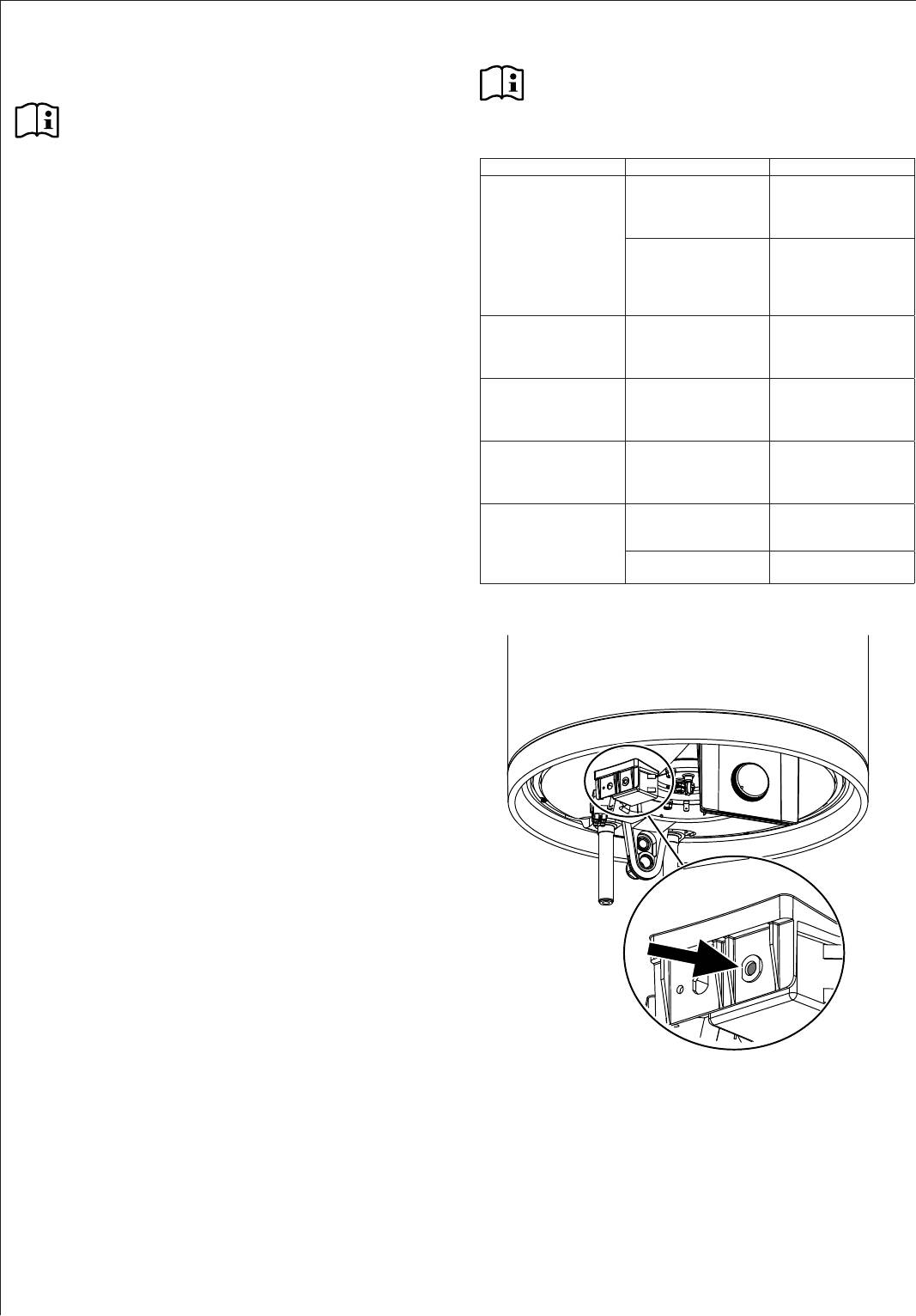
13. Troubleshooting
Note
11.1 Commissioning
-
Note
-
nection.
The water does not
The high limit safety
Remedy the cause of
» -
heat up and the ON/
cut-out has responded
the fault. Replace the
necting the appliance, so that no foreign matter gets
OFF indicator does
because the controller
controller.
not illuminate.
is faulty.
into the water heater or safety valve.
The high limit safety
Press the reset button
» Open the shut-off valve in the cold water feed line.
cut-out has responded
(see diagram).
»
because the temper-
up and the pipework is free of air.
ature has fallen below
-15 °C.
» For this, observe the maximum
The water does not
The heating element
Replace the heating
heat up and the ON/
is faulty.
element.
OFF indicator illumi-
»
nates.
valve of the safety valve.
The water does not
The temperature con-
Replace the tempera-
heat up sufficiently
troller is faulty.
ture controller.
» Turn the temperature selector to maximum.
and the ON/OFF indi-
» Switch the mains power ON.
cator illuminates.
The heat-up time is
The heating element
Descale the heating
» Check the function of the appliance. Ensure that the
very long and the ON/
is scaled up.
element.
thermostat switches off.
OFF indicator illumi-
» Check that the safety valve is working correctly.
nates.
The safety valve
The valve seat is con-
Clean the valve seat.
11.1.1
drips when heating is
taminated.
switched off.
» Explain the function of the appliance and safe-
Water pressure is too
Install a pressure re-
ty valve to users and familiarise them with their
high.
ducing valve.
operation.
» Make users aware of potential dangers, especially
the risk of scalding.
» Hand over these instructions.
11.2 Recommissioning
See chapter "Commissioning".
12.
» Disconnect the appliance from the mains at the
MCB/fuse in the fuse box.
» Drain the appliance. See chapter "Maintenance /
Draining the appliance".
D0000037143
18
Installation - for contractors
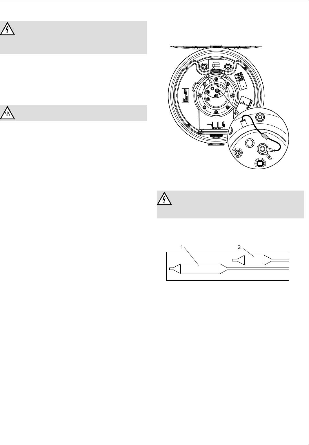
14.5
14.
Ensure that while carrying out maintenance work the an-
WARNING Electrocution
ti-corrosion protection (560 Ω) is not damaged or removed.
Reinsert the anti-corrosion protection correctly after re-
placement.
If you need to drain the appliance, observe chapter
"Draining the appliance".
14.1
» Test the safety valve regularly.
14.2
WARNING Burns
If is necessary to drain the cylinder for maintenance or
to protect the whole installation from frost, proceed as
follows:
» Close the shut-off valve in the cold water feed line.
» Open the DHW valves of all draw-off points until the
appliance is fully drained.
» Drain any residual water from the safety valve.
D0000037141
14.3
14.6
»
DANGER Electrocution
and replace if necessary.
» Next, decide the time intervals at which further
-
checks should be carried out.
14.4
14.7
» Remove loose scale deposits from the water heater.
limiter
» If necessary, descale the inner cylinder with com-
mercially available descaling agents.
21
»
treat the cylinder surface and protective anode with
descaling agents.
D0000037142
1 Controller sensor
2 Limiter sensor
» Insert the controller sensor and the limiter sensor
into the sensor well as far as they will go.
19
Installation - for contractors
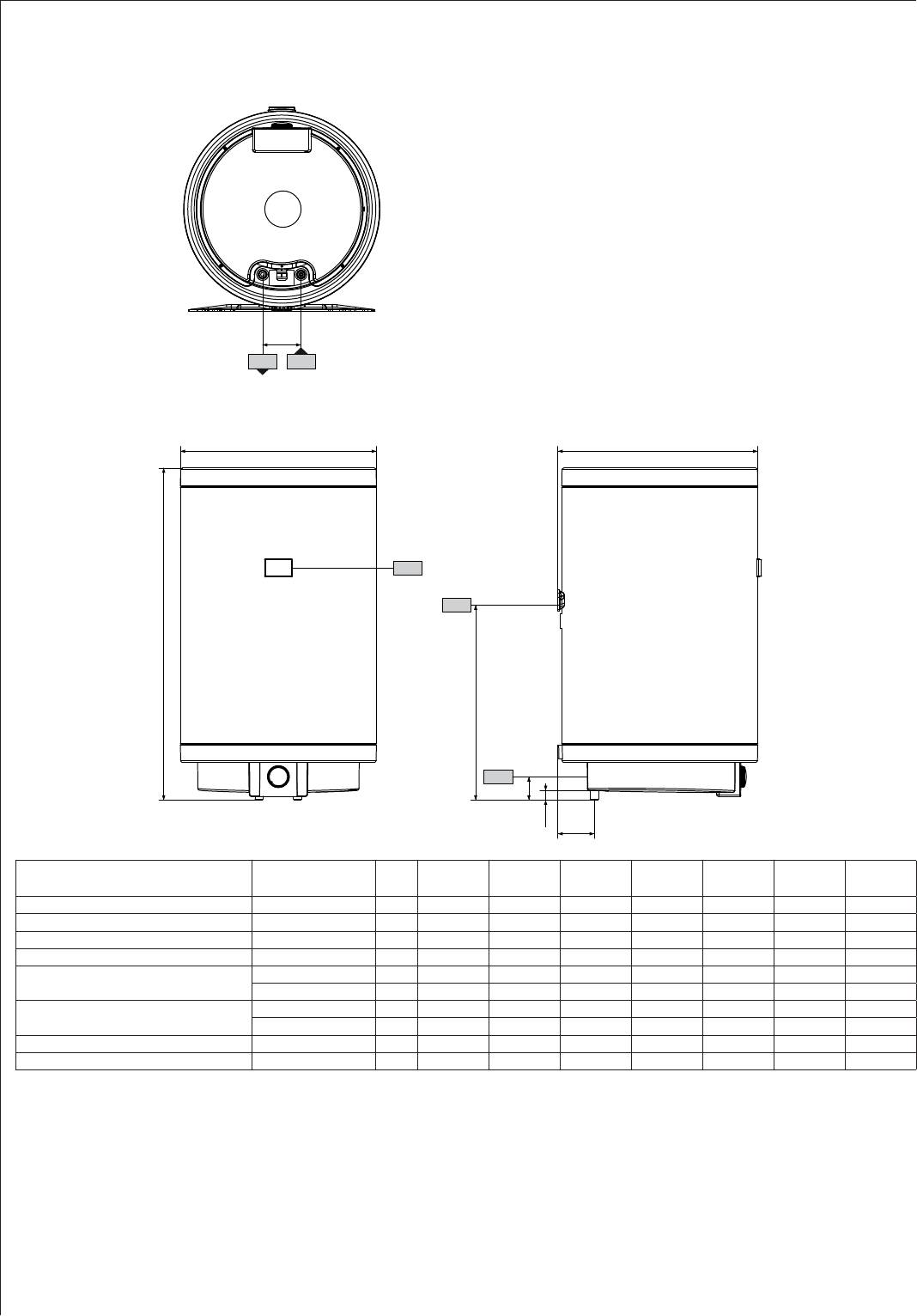
15.
15.1
c06
c01
h46
i13
b01
20
a10
100
a40 a30
61
23
D0000037133
EWH 30
EWH 50
EWH 80
EWH 100
EWH 120
EWH 150
EWH 200
a10 Appliance Height mm 642 897 871 1025 1178 1410 1715
a30 Appliance Depth mm 410 410 520 520 520 520 520
a40 Appliance Diameter mm 405 405 510 510 510 510 510
b01 Entry electrical cables Threaded fitting PG 16 PG 16 PG 16 PG 16 PG 16 PG 16 PG 16
c01 Cold water inlet Male thread G 1/2 A G 1/2 A G 1/2 A G 1/2 A G 1/2 A G 1/2 A G 1/2 A
Rear clearance mm 85.5 85.5 95 95 95 95 95
c06 DHW outlet Male thread G 1/2 A G 1/2 A G 1/2 A G 1/2 A G 1/2 A G 1/2 A G 1/2 A
Rear clearance mm 85.5 85.5 95 95 95 95 95
h46 Temperature indicator
i13 Wall mounting bracket Height mm 530 590 585 735 890 1125 1425
Installation - for contractors
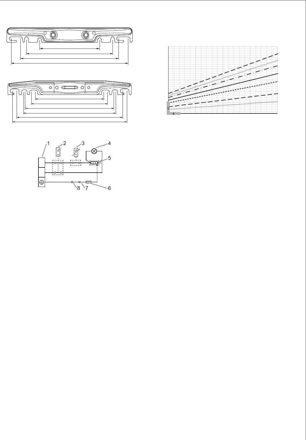
15.3
30 - 50 l
The heat-up time depends on the cylinder capacity, cold
water inlet temperature and heating output.
Graph assumes 15 °C cold water inlet temperature:
184
6
265
300
5
360
80_02_07_0005
4
80 - 200 l
3
2
265
300
1
350
360
0
415
35 45 55 65 75
450
80_02_07_0006
15.2
21 3 4
5
L
N
678
D0000037038
1 Terminal
2 High limit safety cut-out
3 Temperature controller
4 ON/OFF indicator
5 Heating element
6 Electrical resistance 560 ohm
7 Anode
8 Cylinder
21
1
2
3
4
5
6
7
D0000037214
X Temperature setting [°C]
Y Heat-up time [h]
1 150 l
2 200 l
3 120 l
4 100 l
5 80 l
6 50 l
7 30 l
15.4
In the event of a fault, temperatures of up to 95 °C at
0.6 MPa can occur.
WARRANTY
ENVIRONMENT AND RECYCLING
Installation - Warranty - Environment and recycling
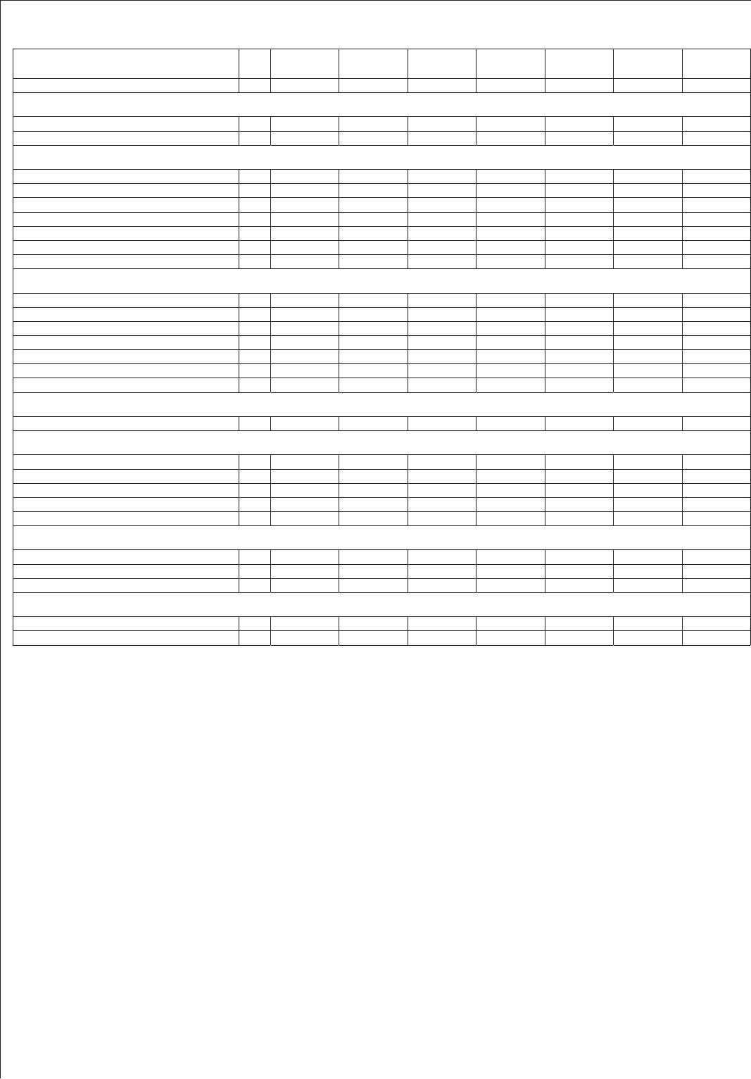
15.5
EWH 30
EWH 50
EWH 80
EWH 100
EWH 120
EWH 150
EWH 200
232087 232088 232089 232090 232091 232092 232093
Nominal capacity l 30 50 80 100 120 150 200
Amount of mixed water 40 °C (15 °C/65 °C) l 52 99 142 186 224 288 376
Connected load ~ 230 V kW 2 2 2 2 2 2 3
Rated voltage V 220-240 220-240 220-240 220-240 220-240 220-240 220-240
Phases 1/N/PE 1/N/PE 1/N/PE 1/N/PE 1/N/PE 1/N/PE 1/N/PE
Frequency Hz 50/60 50/60 50/60 50/60 50/60 50/60 50/60
Single circuit operating mode X X X X X X X
Heat-up time 2.0 kW (15 °C/60 °C) h 0.80 1.33 2.13 2.66 3.20 4.00
Heat-up time 3.0 kW (15 °C/60 °C) h 3.55
Temperature setting range °C 7-75 7-75 7-75 7-75 7-75 7-75 7-75
Max. permissible pressure MPa 0.6 0.6 0.6 0.6 0.6 0.6 0.6
Test pressure MPa 0.2 0.2 0.2 0.2 0.2 0.2 0.2
Max. permissible temperature °C 95 95 95 95 95 95 95
Max. flow rate l/min 23.5 23.5 23.5 23.5 23.5 23.5 23.5
Min. water inlet pressure MPa 0.1 0.1 0.1 0.1 0.1 0.1 0.1
Max. water inlet pressure MPa 0.6 0.6 0.6 0.6 0.6 0.6 0.6
Standby energy consumption/24 h at 65 °C kWh 0.53 0.72 0.79 0.98 1.14 1.33 1.61
Versions
Colour White White White White White White White
IP rating IP25 IP25 IP25 IP25 IP25 IP25 IP25
Sealed unvented type X X X X X X X
Power cable X X X X X X X
Power cable length approx. mm 1000 1000 1000 1000 1000 1000 1000
Dimensions
Height mm 642 897 871 1025 1178 1410 1715
Depth mm 410 410 520 520 520 520 520
Diameter mm 405 405 510 510 510 510 510
Weights
Weight, empty kg 16.4 21.4 28.2 33.6 39.1 46.2 56.3
Weight, full kg 46.4 71.4 108.2 133.6 159.1 196.2 256.3
Warranty
The warranty conditions of our German companies do not
apply to appliances acquired outside of Germany. In countries
where our subsidiaries sell our products, it is increasingly the
case that warranties can only be issued by those subsidiaries.
Such warranties are only granted if the subsidiary has issued
its own terms of warranty. No other warranty will be granted.
We shall not provide any warranty for appliances acquired in
countries where we have no subsidiary to sell our products.
This will not aect warranties issued by any importers.
Environment and recycling
We would ask you to help protect the environment. After use,
dispose of the various materials in accordance with national
regulations.
22


