Pioneer DJM-350-W: Operations
Operations: Pioneer DJM-350-W
Operations
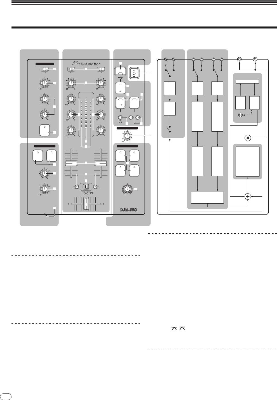
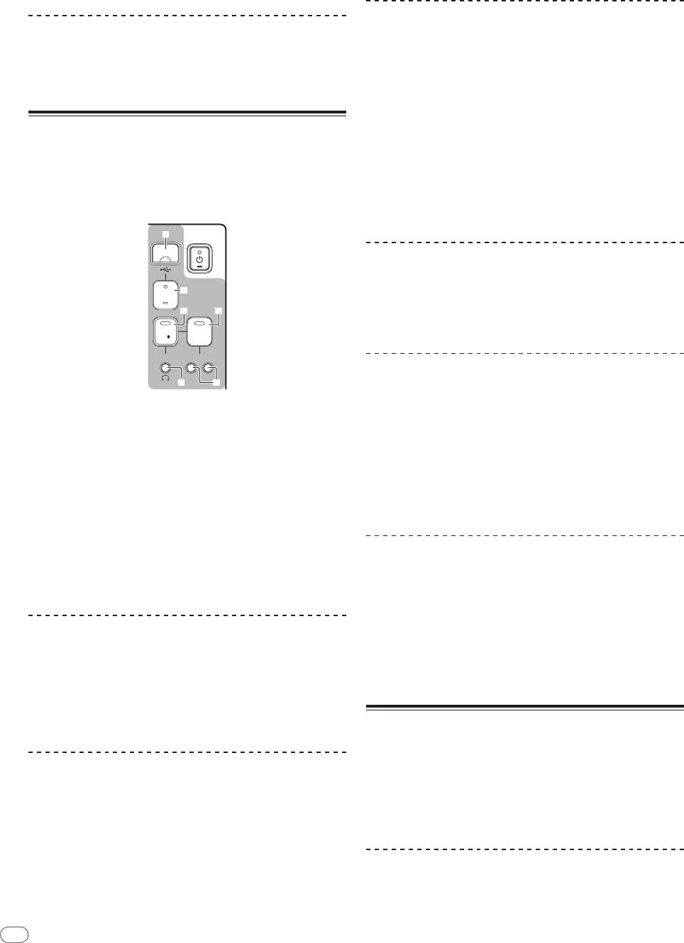
Control panel
8
En
DRB1501-D
8
Flow of audio signals
USB recording
MASTER
MASTER
MIC/AUX section Mixer section
MIC
AUX
CD1 PHONO1 CD2 PHONO2
section
OUT 2
OUT 1
MIC /AUX
k
3
b
MIC
AUX
CD
PHONO
CD
PHONO
1
LEVEL
TRIM TRIM
USB I/F
4
c
USB
l
0
9
9
STOP
LEVEL
TRIM
TRIM
HI
HI
HI
MASTER
m n
CH- 1CH- 2
REC
PLAY
12
12
9
9
RECPLAY
LOW
5
MID
MID
EQ
TRACK MARK SEARCH
d d
EQ/
EQ/
12
12
9
9
ISOLATOR
ISOLATOR
PREVIEW
LOW
LOW
PREVIEW
o
p
MASTER LEVEL
MIC/AUX
MIC/AUX
ON/OFF
MASTER
ON
6
LEVEL
LEVEL
9
9
2
CH- 1
e
CH-2
0
HEADPHONES
f
MASTER EFFECT
CH-1
CH-2
GATE JET
CUE
CUE
CH
CH
MASTER
g
q
FADER
FADER
7
EFFECT
MIXING
FILTERCRUSH
8
h
CUE MASTER
LEVEL
i
LEVEL/DEPTH
FADER
FADER
START
START
9
r
THRU
0
CROSS FADER
j
2 CHANNEL DJ MIXER
a
PHONES
Headphones section
Master effect section
1 u (Power switch) (page 9)
Mixer section
2 MASTER LEVEL (page 9)
Two sets of audio signals can be adjusted separately for basic DJ
mixing (page 9).
MIC/
AUX section
b CD, PHONO (input selector switch)
The sound of a microphone or external device (sampler, portable audio
c TRIM
device, etc.) can be handled (page 11).
d HI, MID, LOW
3 MIC, AUX
e Master level indicator
4 LEVEL
f Channel level indicator
5 HI, LOW
g Channel fader
6 MIC/AUX ON
h FADER START
i THRU,
, (crossfader curve selector switch)
Headphones section
The sound being input to this unit can be checked over headphones
j Crossfader
(page 11).
7 CH-1 CUE, CH-2 CUE
USB recording section
8 MIXING
DJ performances can be recorded onto and played from USB devices
(page 12).
9 LEVEL
k USB device insertion slot
a PHONES
l USB STOP
m REC k/
g
English
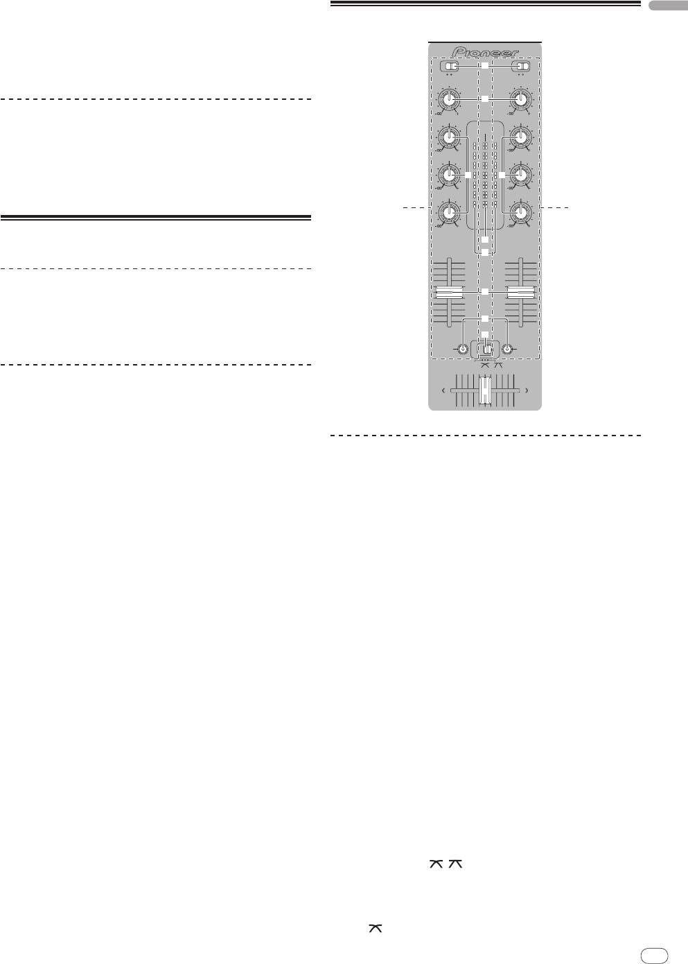
Basic operations (mixer section)
n PLAY f
o TRACK MARK (PREVIEW)
p SEARCH o, p
Master effect section
Effects can be applied to the sound output from [MASTER OUT 1, 2]
(page 11).
q MASTER EFFECT (GATE, CRUSH, JET, FILTER)
r LEVEL/
DEPTH
About the power switch of this unit
To turn the power on
Press [u] 1.
Turn on the power of this unit.
The [u] indicator lights green.
To set to the standby mode
When this unit’s power is on, press [u] 1 for at least 2
seconds.
This unit is set to the standby mode.
The [u] indicator lights red.
! When [u] is pressed again, the power turns on.
! This unit is equipped with an auto standby function. For details,
see About the auto standby function on page 12.
En
9
DRB1501-D
98
b
CD
PHONO
CD
PHONO
TRIM TRIM
c
9
9
HI
HI
MASTER
CH- 1 CH- 2
9
9
MID
MID
d d
9
9
LOW
LOW
1 2
LEVEL
9
9
CH- 1
e
CH-2
f
g
h
i
FADER
FADER
START
START
THRU
j
Outputting sound
Check that this unit is properly connected to the DJ player, etc., before
outputting sound. For instructions on connections, see Connecting the
input/
output terminals on page 7.
Set the volume of the power amplifiers connected to the [MASTER
OUT 1, 2] terminals to an appropriate level. Note that very loud sounds
will be output if the volume is set too high.
To output the sound of channel 1 [CH-1] 1
To output the sound of channel 2 ([CH-2]) 2, perform the procedure
below replacing [CH-1] with [CH-2].
1 Switch the [CD, PHONO] (input selector) switch b for
the [CH-1] 1.
Select the input source for [CH-1] from among the devices connected
to this unit.
— [CD]: Selects the DJ player connected to the [CD] terminals.
— [PHONO]: Selects the analog player connected to the
[PHONO] terminals.
2 Turn the [TRIM] c control for the [CH-1] 1 clockwise.
Adjusts the audio level input to the [CH-1] terminal.
The [CH-1] channel level indicator f lights when audio signals are
being properly input to [CH-1].
Adjust [TRIM] so that the orange indicator lights at the point in the
track where the volume is loudest (the climax, etc.).
Be careful that the red indicator does not light, or the sound could be
distorted.
3 Move the [CH-1] 1 channel fader g to the back side.
The level of the sound output from the [CH-1] terminals is adjusted.
4 Switch [THRU, , ] (the crossfader curve selector
switch) i.
This switches the crossfader curve characteristics.
— [THRU]: Choose this when you do not want to use the
crossfader.
— [ ]: Set here for a curve that rises gradually.
— [ ]: Set here for a curve that rises steeply. (When the cross-
Mixing using the crossfader
fader moves away from either the left or right edge, the sound
is immediately output from the opposite side.)
1 Set [THRU,
, ] (the crossfader curve selector
5 Move the crossfader j.
switch) i to [ ] or [ ].
Switch the channel whose sound is output from the speakers.
2 Operate [CH-2] 2.
— Left edge: The [CH-1] sound is output.
Operate as described in steps 2 to 6 under Mixing using the channel
— Center position: The sound of [CH-1] and [CH-2] is mixed and
faders on page 10.
output.
— Right edge: The [CH-2] sound is output.
3 Move the crossfader j gradually to the right.
! This operation is not necessary when the [THRU,
, ] (cross-
While checking the sound output from the speakers, operate the
fader curve selector) switch is set to [THRU].
crossfader to substitute the sound of [CH-1] with the sound of [CH-2].
Mixing is completed once only the [CH-2] sound is being output from
6 Turn [MASTER LEVEL] 2 clockwise.
the speakers.
Sound is output from the speakers.
The master level indicator e on the control panel lights.
Adjust [MASTER LEVEL] so that the orange indicator lights at the point
in the track where the volume is loudest (the climax, etc.).
Using the fader to play a Pioneer DJ
Be careful that the red indicator does not light, or the sound could be
player (fader start)
distorted.
If you connect a Pioneer DJ player using a control cable (supplied with
a DJ player), you can start playback of control other operations of the
DJ player with the fader of this unit.
Adjusting the sound quality
The fader start function can only be used when connected to a Pioneer
DJ player.
Turn the [CH-1] 1 or [CH-2] 2 [HI], [MID] or [LOW] d
Connect this unit and Pioneer DJ player beforehand. For instructions
control.
on connections, see Connecting the input/
output terminals on page 7.
Refer to Specifications on page 16 for the range of sound that can be
adjusted by each control.
To start playback using the channel faders
! The sound for that range can be turned completely off by turning
the control all the way counterclockwise (isolator function).
1 Set [THRU,
, ] (the crossfader curve selection
switch) i to [THRU].
Mixing using the faders
2 Press [FADER START] h.
Prepare the unit in advance so that the sound of [CH-1] 1 is being out-
Turn the fader start function on.
put from the speakers. For instructions on preparation, see Outputting
3 Move the channel fader g all the way to the front.
sound on page 9.
For instructions on monitoring the sound, see Monitoring the sound
4 Set the cue on the DJ player.
over headphones (headphones section) on page 11.
The DJ player pauses playback at the cue point.
Mixing using the channel faders
5 Move the channel fader g to the back.
Playback starts on the DJ player.
! If you set the channel fader back to the original position, the player
1 Set [THRU,
, ] (the crossfader curve selection
instantaneously returns to the cue point already set and pauses
switch) i to [THRU].
playback (back cue).
2 Switch the [CD, PHONO] (input selector) switch b for
To start playback using the crossfader
the [CH-2] 2.
3 Turn the [TRIM] c control for the [CH-2] 2 clockwise.
1 Set [THRU,
, ] (the crossfader curve selector
switch) i to [ ] or [ ].
4 Press [CH-2 CUE] 7.
The sound of [CH-2] is monitored from the headphones.
2 Press [FADER START] h.
Turn the fader start function on.
5 Turn [MIXING] 8.
This adjusts the balance of the monitor volume between the sound
3 Move the crossfader j.
output from the [MASTER OUT 1, 2] terminals (the sound of [CH-1])
Move the crossfader to the opposite edge from the channel for which
and the sound of [CH-2].
you want to use the fader start function.
6 Operate the DJ player connected to the [CH-2]
4 Set the cue on the DJ player.
terminals.
The DJ player pauses playback at the cue point.
While checking the sound over the headphones, adjust the tempo of
[CH-2] track to match the tempo of [CH-1] track.
5 Move the crossfader j.
Playback starts on the DJ player.
7 While moving the [CH-2] 2 channel fader to the back,
! If you set the crossfader back to the original position, the player
move the [CH-1] 1 channel fader to the front.
instantaneously returns to the cue point already set and pauses
While checking the sound output from the speakers, operate the chan-
playback (back cue).
nel faders to substitute the sound of [CH-1] with the sound of [CH-2].
Mixing is completed once only the [CH-2] sound is being output from
the speakers.
10
En
DRB1501-D
10
English
Monitoring the sound over
headphones (headphones section)
En
11
DRB1501-D
1110
HEADPHONES
CH-1
CH-2
CUE
CUE
7
MIXING
8
CUE MASTER
LEVEL
9
0
a
PHONES
1 Connect headphones to the [PHONES] jack.
For instructions on connections, see Connecting the input/
output
terminals on page 7.
2 Press [CH-1 CUE] or [CH-2 CUE] 7.
Select the channel you want to monitor.
— [CH-1 CUE]: The sound of [CH-1] is monitored.
— [CH-2 CUE]: The sound of [CH-2] is monitored.
! This operation is not necessary to monitor the master channel
sound (the sound output from the [MASTER OUT 1, 2] terminals).
3 Turn [MIXING] 8.
— When turned counterclockwise: The volume of [CH-1] and
[CH-2] becomes relatively louder.
— At the center position: The sound of [CH-1] and [CH-2] has
the same volume as the sound from the [MASTER OUT 1, 2]
terminals.
— When turned clockwise: The volume of the sound output from
the [MASTER OUT 1, 2] terminals becomes relatively louder.
4 Turn [LEVEL] 9 in the headphones section clockwise.
Sound is output from the headphones.
! Monitoring is canceled when [CH-1 CUE] or [CH-2 CUE] is pressed
again.
! Monitoring of the sound output from the [MASTER OUT 1, 2] termi-
nals cannot be canceled.
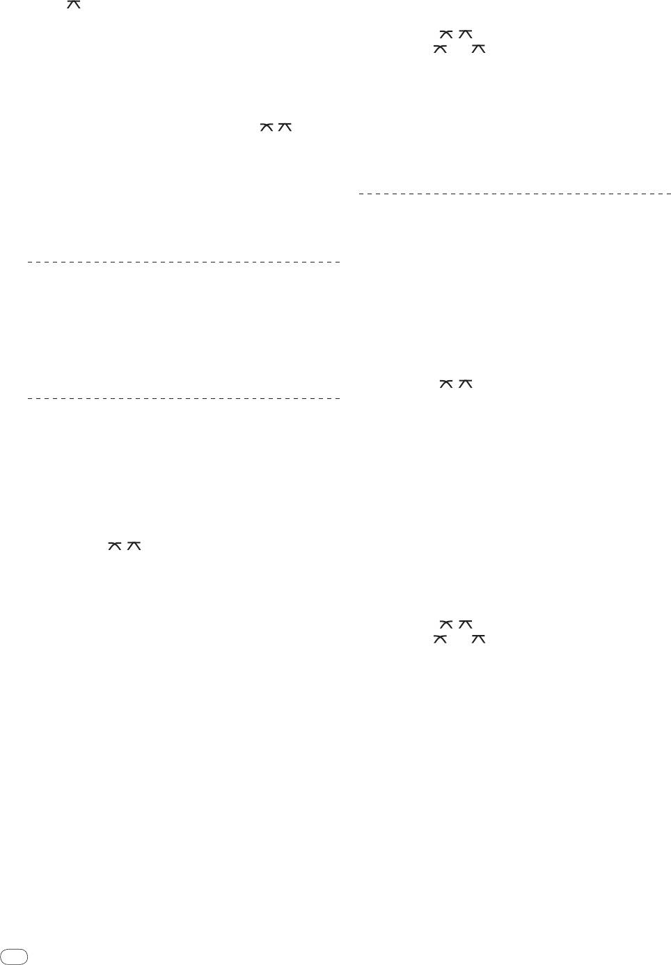
Using the effect function (master
effect section)
This unit is equipped with four effect buttons. When an effect button
is pressed, the corresponding effect is applied to the audio signals
output from the [MASTER OUT 1, 2] terminals.
MASTER EFFECT
GATE JET
q
FILTERCRUSH
LEVEL/DEPTH
r
2 CHANNEL DJ MIXER
Applying an effect
Press one of the [MASTER EFFECT (GATE, CRUSH, JET,
FILTER)] q buttons.
The effect is applied to the sound.
The button that was pressed flashes.
The effect differs for the different buttons. For details on the different
effects, see the table below.
! When a button that is flashing is pressed again, the effect is turned
off.
Effect Name Descriptions LEVEL/
DEPTH
Left: The high range (high
The distinctive range is
hat, etc.) is given variation.
cut from the sound of the
GATE
Right: The low range (bass
track’s rhythm section to
drum, etc.) is given varia-
give variation to the rhythm.
tion.
Left: The sound is crushed
and an effect as if the high
range was gradually cut is
The sound is moderately
achieved.
CRUSH
crushed, adding accent.
Right: The sound is crushed
and an effect as if the low
range was gradually cut is
achieved.
Left: An effect like a jet
An effect like a jet ascend-
descending is achieved.
JET
ing and descending is
Right: An effect like a jet
achieved.
ascending is achieved.
Left: An effect as if the high
range was gradually cut is
The sound of the high or
achieved.
FILTER
low range is filtered out,
Right: An effect as if the low
greatly changing the tone.
range was gradually cut is
achieved.
Varying the effect
Turn [LEVEL/
DEPTH] r.
The effect changes according to the direction in which the [LEVEL/
DEPTH] is turned and its position.
! The original sound is output when [LEVEL/
DEPTH] is set to the
center position.
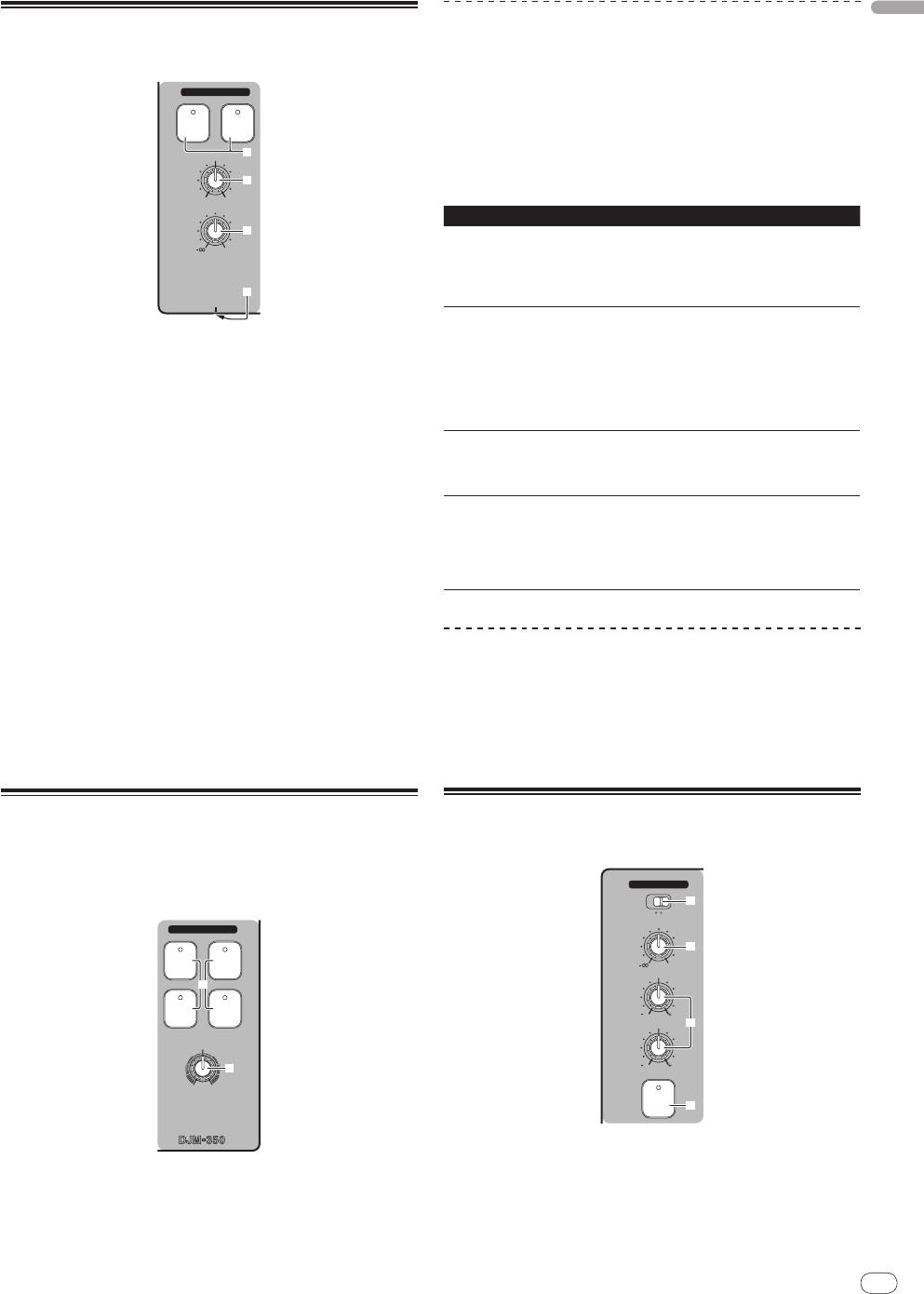
Using a microphone or external
device (MIC/
AUX section)
MIC /AUX
3
MIC
AUX
LEVEL
4
0
HI
12
12
LOW
5
12
12
MIC/AUX
ON
6
1 Switch [MIC, AUX] 3.
— [MIC]: The microphone connected to the [MIC] terminal is
selected.
— [AUX]: The external device connected to the [AUX] terminals
is selected.
2 Press [MIC/AUX ON] 6.
3 Turn [LEVEL] 4 in the MIC/
AUX section clockwise.
The sound of the microphone or external device is output from the
speakers.
Adjusting the sound quality
Turn [HI] or [LOW] 5 in the MIC/
AUX section.
Refer to Specifications on page 16 for the range of sound that can be
adjusted by each control.
Recording the performance (USB
recording section)
The same sound as the sound being output from the [MASTER OUT 1,
2] terminals can be recorded as a WAV file on a USB device.
! The name of the files created when the sound is recorded is in the
format [REC***.WAV] (*** is a 3-digit number).
12
En
DRB1501-D
12
k
USB
l
STOP
m n
REC
PLAY
TRACK MARK SEARCH
PREVIEW
o
p
! Previewing is not possible while the track is being recorded or
played.
Fast-forwarding/
reversing recorded
tracks
During playback, press and hold in [SEARCH o, p] p.
The track is fast-forwarded when [p] is pressed and held in.
The track is fast reversed when [o] is pressed and held in.
The [PLAY f] indicator flashes during fast-forwarding/
reversing.
! Fast-forwarding/
reversing is not possible when in the pause mode.
Cuing to the beginning of recorded tracks
Press [SEARCH o, p] p.
Press the [p] to move to the beginning of the next track.
Press [o] once to move to the beginning of the currently playing
track, twice to move to the beginning of the previous track.
Splitting tracks while recording
During recording, press [TRACK MARK (PREVIEW)] o.
The currently recording track is split and stored on the USB device.
! When split tracks are played on this unit, the sound may be inter-
rupted at the boundary between the two tracks.
Deleting recorded tracks
1 While playing the track, press [PLAY f] n.
1 Insert the USB device into the USB device insertion
The track you want to delete is paused.
slot k.
The [USB STOP] indicator l flashes.
2 Press [PLAY f] n for at least 2 seconds.
After a while, the [USB STOP] indicator stops flashing, remaining lit,
The [REC k/
g] indicator flashes.
and the recording standby mode is set.
3 While pressing [PLAY f] n, press [REC k/
g] m.
2 Press [REC k/
g] m.
The [REC k/
g] indicator lights and the track is deleted.
Recording starts.
! Track deleting is canceled if [PLAY f] is released while the [REC
The [REC k/
g] indicator m flashes.
k/
g] indicator is flashing.
! When [REC k/
g] is pressed again, the [REC k/
g] indicator turns
off and recording stops.
! Continuous recording is possible for 180 minutes. If recording con-
Disconnecting USB devices
tinues for over 180 minutes, the recording data on the USB device
Always perform the following procedure to disconnect USB devices.
is automatically split.
Pulling the USB device out without performing this procedure could
! Recording is possible for about 90 minutes on a 1 GB USB device.
make the USB device unreadable.
When turning the set’s power off, be sure to remove the USB device
first.
Playing recorded tracks
1 Press [USB STOP] l for at least 1 second.
Press [PLAY f] n.
The [USB STOP] indicator flashes, then turns off.
Playback starts.
2 Disconnect the USB device.
The [PLAY f] indicator n lights.
! When [PLAY f] is pressed again, playback is paused.
! Only WAV files stored in the [PIONEER DJM / DJM350 REC] folder
on the USB device can be played.
About the auto standby function
When the auto standby function is turned on, the power is automati-
cally set to the standby mode after the set time has passed with all of
Previewing recorded tracks
the conditions below met.
— That none of this unit’s buttons or controls are operated.
1 Turn [MIXING] 8 counterclockwise from the center
— That this unit’s channel level indicator is not lit.
position.
— That the USB device’s recording and playback functions are not in
use.
2 Press and hold in [TRACK MARK (PREVIEW)] o.
The sound of the recorded track can be heard over the headphones
while the button is pressed.
Setting the auto standby function
! The sound being previewed is added to the sound of [CH-1] and
[CH-2] and output from the headphones.
First set this unit to the standby mode.
! The sound being previewed is not output from the speakers.

1 Press [u] 1 while pressing [o] and [p] p.
English
This unit switches to the mode for changing the auto standby func-
tion’s setting.
The topmost point on the master level indicator flashes. The other
points on the indicator light according to the currently set time.
2 Press [o] or [p] p.
Set the time until the standby mode is set.
The set time switches each time the button is pressed.
The points on the master level indicator light according to the set time
(not including the topmost point).
— Off — 20 minutes — 40 minutes — 60 minutes
— 20 minutes: The bottom two points light.
— 40 minutes: The bottom four points light.
— 60 minutes: The bottom six points light.
! The time is set to 20 minutes upon shipment from the factory.
3 Press [u] 1 for at least 2 seconds.
The new auto standby function setting is saved.
The [u] indicator flashes green while the setting is being saved, then
stops flashing, remaining lit, once the setting has been saved.
! Do not disconnect the power cord while the setting is being saved.
En
13
DRB1501-D
1312
Оглавление
- Before start
- Connections
- Operations
- Additional information
- Informations préliminaires
- Raccordements
- Opérations
- Informations supplémentaires
- Vor der Inbetriebnahme
- Anschlüsse
- Bedienungen
- Zusätzliche Informationen
- Prima di cominciare
- Collegamenti
- Operazioni
- Informazioni aggiuntive
- Alvorens te beginnen
- Aansluitingen
- Bediening
- Aanvullende informatie
- Antes de empezar a usar la unidad
- Conexiones
- Operaciones
- Información adicional
- До начала
- Подключения
- Операции
- Дополнительная информация


