Pioneer gm-a5602: Connecting the units
Connecting the units: Pioneer gm-a5602
Section
03
Connecting the units
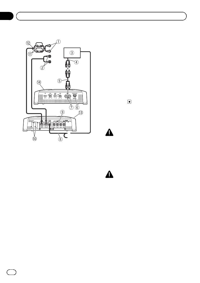
The female terminal can be connected to the
Connection diagram
auto-antenna relay control terminal. If the car
stereo lacks a system remote control terminal,
connect the male terminal to the power term-
inal via the ignition switch.
9 Speaker output terminals
Please see the following section for speaker
connection instructions. Refer to Connections
when using the speaker input wire on page 8.
a Fuse 30 A × 2 (GM-A5602) / 25 A ×1 (GM-
A3602)
b Fuse (30 A) × 2
c Grommet
d Rear side
e Front side
Before connecting the
amplifier
WARNING
! Secure the wiring with cable clamps or adhe-
sive tape. To protect the wiring, wrap sections
1 Special red battery wire
in contact with metal parts in adhesive tape.
RD-223 (sold separately)
! Never cut the insulation of the power supply
After completing all other amplifier connec-
to feed power to other equipment. Current ca-
tions, finally connect the battery wire terminal
pacity of the wire is limited.
of the amplifier to the positive + battery term-
inal.
CAUTION
2 Ground wire (Black)
! Never shorten any wires, the protection circuit
RD-223 (sold separately)
may malfunction.
Connect to metal body or chassis.
! Never wire the speaker negative cable directly
3 Car stereo with RCA output jacks (sold sepa-
to ground.
rately)
! Never band together multiple speaker’s nega-
4 External output
tive cables.
5 Connecting wire with RCA pin plugs (sold se-
! If the system remote control wire of the ampli-
parately)
fier is connected to the power terminal via the
6 Speaker input terminal (use a connector in-
ignition switch (12 V DC), the amplifier will re-
cluded)
main on with the ignition whether the car
Please see the following section for speaker
stereo is on or off, which may exhaust battery
connection instructions. Refer to Connections
if the engine is at rest or idling.
when using the speaker input wire on page 8.
7 RCA input jack
8 System remote control wire (sold separately)
Connect male terminal of this wire to the sys-
tem remote control terminal of the car stereo.
6
En
Section
Connecting the units
03
English
! Install and route the separately sold battery
to 8 W for stereo connection, or 4 W to 8 W for
wire as far as possible from the speaker wires.
monaural and other bridge connection.
Install and route the separately sold battery
Subwoofer
wire, ground wire, speaker wires and the am-
plifier as far away as possible from the anten-
Speaker channel Power
na, antenna cable and tuner.
Nominal input:
Two-channel output
Min. 150 W (GM-A5602)
Min. 60 W (GM-A3602)
About bridged mode
Nominal input:
One-channel output
Min. 450 W (GM-A5602)
Min. 180 W (GM-A3602)
Other than subwoofer
Speaker channel Power
MAX input:
Two-channel output
Min. 300 W (GM-A5602)
Min. 120 W (GM-A3602)
MAX input:
One-channel output
Min. 900 W (GM-A5602)
Min. 400 W (GM-A3602)
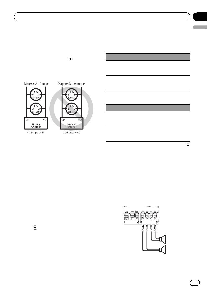
! Do not install or use this amplifier by wiring
speakers rated at 4 W (or lower) in parallel to
achieve a 2 W (or lower) bridged mode (Dia-
gram B).
Amplifier damage, smoke, and overheating
Connecting the speakers
could result from improper bridging. The am-
The speaker output mode can be two-channel
plifier surface could also become hot to the
(stereo) or one-channel (mono). Connect the
touch and minor burns could result.
speaker leads to suit the mode according to
To properly install or use a bridged mode and
the figures shown below.
achieve a 4 W load, wire two 8 W speakers in
parallel with Left + and Right * (Diagram A)
Two-channel output (Stereo)
or use a single 4 W speaker.
In addition, refer to the speaker instruction
manual for information on the correct connec-
tion procedure.
! For any further enquiries, contact your local
authorized Pioneer dealer or customer
service.
1
About suitable
2
specification of speaker
Ensure speakers conform to the following
1 Speaker (Left)
standards, otherwise there is a risk of fire,
2 Speaker (Right)
smoke or damage. Speaker impedance is 2 W
7
En
Section
03
Connecting the units
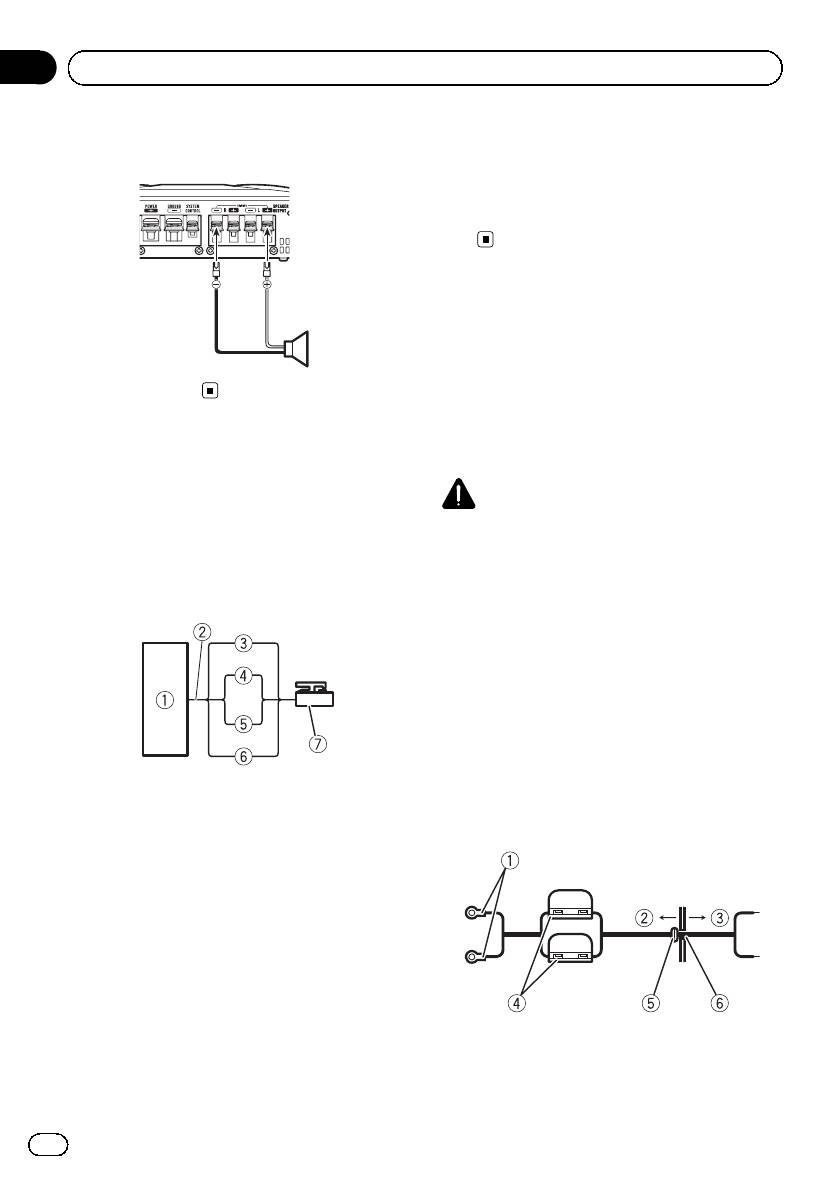
One-channel output
work with some headunits. In such cases, please
use a system remote control wire (sold sepa-
rately). If multiple amplifiers are to be connected
together synchronously, connect the head unit
and all amplifiers via the system remote control
wire.
Connecting the power
terminal
1
The use of a special red battery and ground
wire RD-223 (sold separately) is recom-
1 Speaker (Mono)
mended. Connect the battery wire directly to
the car battery positive terminal + and the
ground wire to the car body.
Connections when using
the speaker input wire
WARNING
Connect the car stereo speaker output wires
If the battery wire is not securely fixed to the term-
to the amplifier using the supplied speaker
inal using the terminal screws, there is a risk of
input wire.
overheating, malfunction and injury, including
! Do not connect both the RCA input and the
minor burns.
speaker input at the same time.
1 Route battery wire from engine com-
partment to the vehicle interior.
! When drilling a cable pass-hole into the ve-
hicle body and routing a battery wire thor-
ough it, take care not to short-circuit the
wire damaging it by the cut edges or burrs
of the hole.
After completing all other amplifier connec-
1 Car Stereo
tions, finally connect the battery wire terminal
2 Speaker output
of the amplifier to the positive + battery term-
3 White/black: Left *
inal.
4 White: Left +
5 Gray/black: Right *
6 Gray: Right +
7 Speaker input connector
To speaker input terminal of this unit.
Note
If speaker input wires from a headunit are con-
nected to this amplifier, the amplifier will automa-
tically turn on when the headunit is turned on.
1 Positive + terminal
When the headunit is turned off, the amplifier
2 Engine compartment
turns off automatically. This function may not
3 Vehicle interior
4 Fuse (30 A) × 2
8
En
Section
Connecting the units
03
English
5 Insert the O-ring rubber grommet into the
4 Terminal screws
vehicle body.
5 Battery wire
6 Drill a 14 mm hole into the vehicle body.
6 Ground wire
7 System remote control wire
2 Twist the battery wire, ground wire
and system remote control wire.
Twist
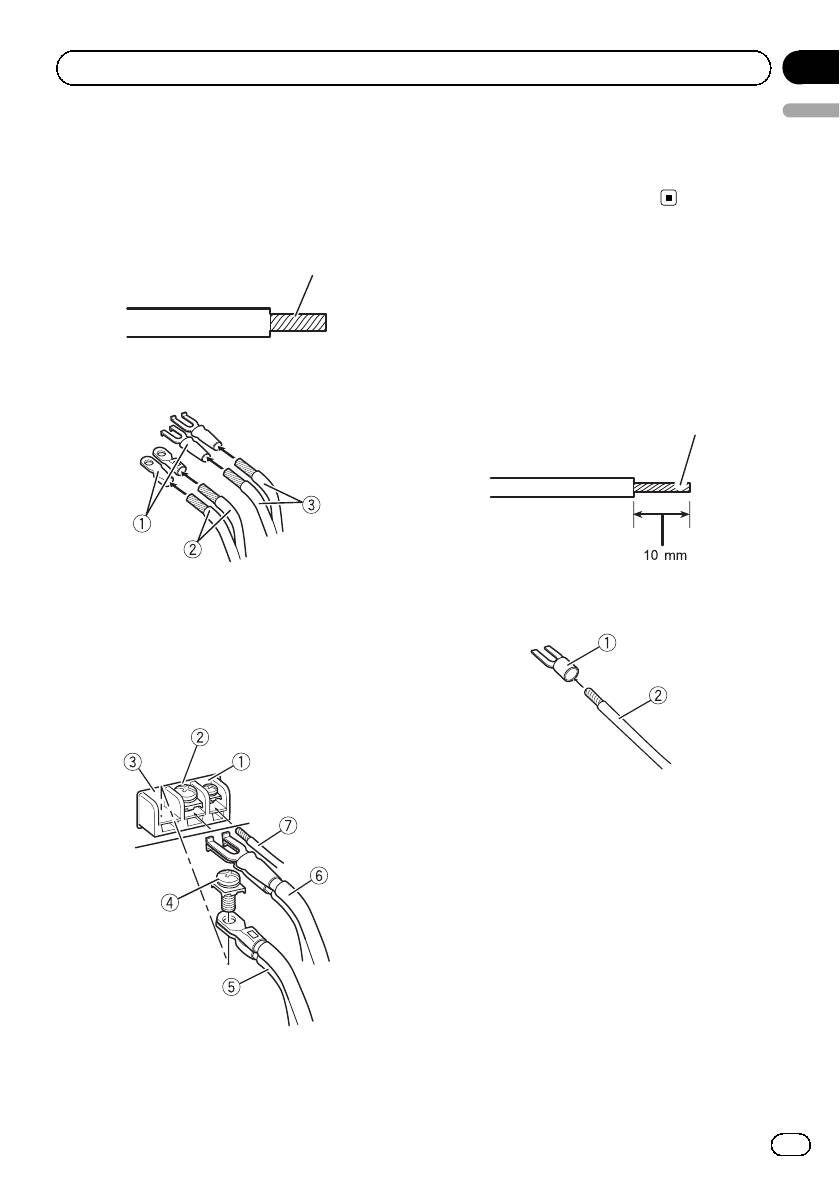
Connecting the speaker
output terminals
1 Use wire cutters or a utility knife to
strip the end of the speaker wires to ex-
3 Attach lugs to wire ends.
pose about 10 mm of wire and then twist
Use pliers, etc., to crimp lugs to wires.
the wire.
Twist
1 Lug (sold separately)
2 Attach lugs to wire ends.
2 Battery wire
Use pliers, etc., to crimp lugs to wires.
3 Ground wire
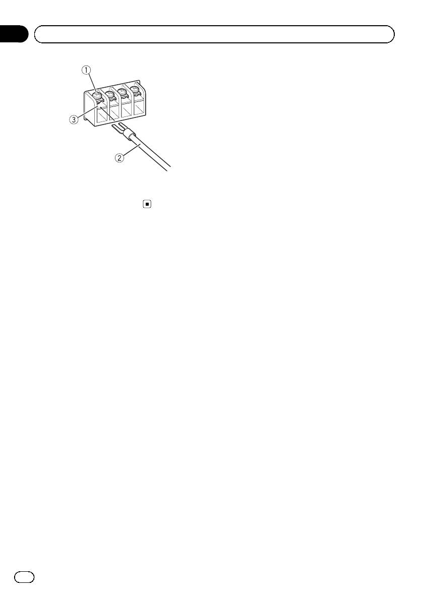
4 Connect the wires to the terminal.
Fix the wires securely with the terminal
screws.
1 Lug (sold separately)
2 Speaker wire
3 Connect the speaker wires to the
speaker output terminals.
Fix the speaker wires securely with the term-
inal screws.
1 System remote control terminal
2 Ground terminal
3 Power terminal
9
En
Section
03
Connecting the units
1 Terminal screws
2 Speaker wires
3 Speaker output terminals
10
En
Оглавление
- Before you start
- Setting the unit
- Connecting the units
- Before installing the amplifier
- Additional information
- Avant de commencer
- Réglage de l’appareil
- Connexion des appareils
- Installation
- Informations complémentai res
- Prima di iniziare
- Impostazione dell’unità
- Collegamento delle unità
- Installazione
- Informazioni supplementari
- Antes de comenzar
- Configuración de la unidad
- Conexión de las unidades
- Instalación
- Información adicional
- Bevor Sie beginnen
- Einstellen des Geräts
- Anschließen der Geräte
- Installation
- Zusätzliche Informationen
- Vóór u begint
- Het toestel installeren
- De toestellen aanslui ten
- Installatie
- Aanvullende informatie
- Перед началом эксплуатации
- Настройка усилителя
- Подключение устройств
- Подключение устройств Технические характеристики Подключение громкоговорителя громкоговорителей
- Подключение устройств
- Установка
- Дополнительная информация Серийный номер
- Дополнительная информация


