Pioneer DEH-200MP: Connections
Connections: Pioneer DEH-200MP
Section
03
Connections
! Control signal is output through blue/white
Important
cable when this unit is powered on. Connect it
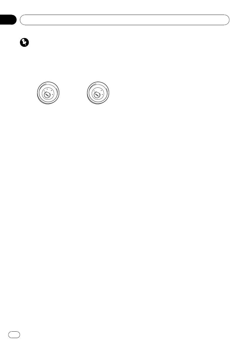
! When this unit is installed in a vehicle without
to an external power amp’s system remote
ACC (accessory) position on the ignition
control or the vehicle’s auto-antenna relay
switch, red cable must be wired to the term-
control terminal (max. 300 mA 12 V DC). If the
inal that can detect the operation of the igni-
vehicle is equipped with a glass antenna, con-
tion key. Otherwise, battery drain may result.
nect it to the antenna booster power supply
terminal.
A
C
C
F
F
O
N
O
F
F
N
O
! Never connect blue/white cable to external
S
O
S
T
T
A
A
R
R
power amp’s power terminal. Also, never con-
T
T
nect it to the power terminal of the auto anten-
ACC position No ACC position
na. Other wise, battery drain or malfunction
may result.
! Use of this unit in conditions other than the
! Black cable is ground. This cable and other
following could result in fire or malfunction.
product’s ground cable (especially, high-cur-
— Vehicles with a 12-volt battery and negative
rent products such as power amp) must be
grounding.
wired separately. Otherwise, fire or malfunc-
— Speakers with 50 W (output value) and 4
tion may result if they are accidentally de-
ohm to 8 ohm (impedance value).
tached.
! To prevent a short-circuit, overheating or mal-
function, be sure to follow the directions
below.
— Disconnect the negative terminal of the
battery before installation.
— Secure the wiring with cable clamps or ad-
hesive tape. To protect the wiring, wrap ad-
hesive tape around them where they lie
against metal parts.
— Place all cables away from moving parts,
such as gear shift and seat rails.
— Place all cables away from hot places,
such as near the heater outlet.
— Do not pass the yellow cable through a
hole into the engine compartment to con-
nect to a battery.
— Cover any disconnected cable connectors
with insulating tape.
— Do not shorten any cables.
— Never cut the insulation of the power cable
of this unit in order to share the power
with other devices. Current capacity of the
cable is limited.
— Use a fuse of the rating prescribed.
— Never wire the speaker negative cable di-
rectly to ground.
— Never band together multiple speaker’s ne-
gative cables.
14
En
Section
Connections
03
English
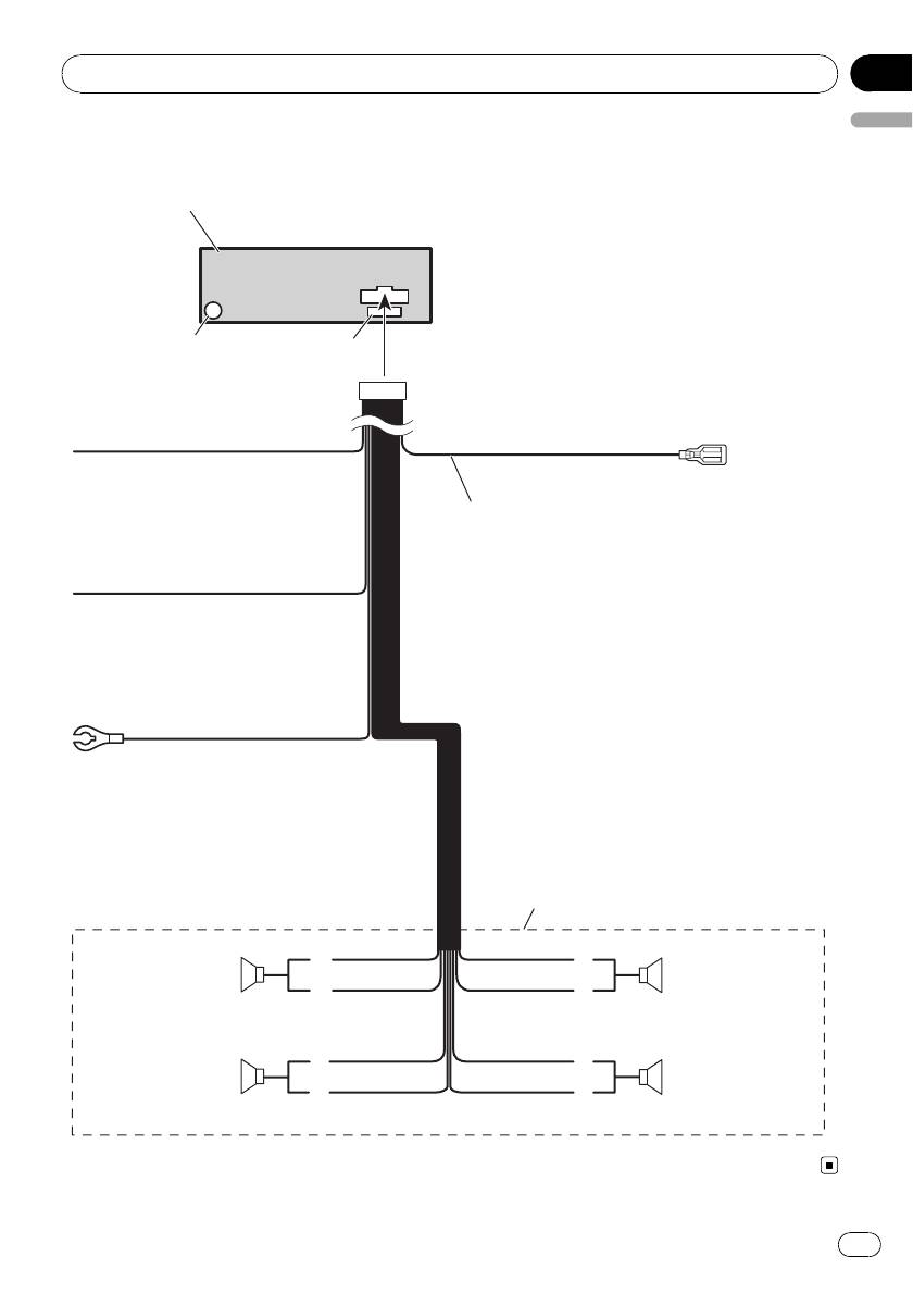
Connection Diagram
This product
Antenna jack
Fuse (10 A)
Yellow
Connect to the constant 12 V
supply terminal.
Blue/white
Connect to system control terminal of the
power amp or auto-antenna relay control
terminal (max. 300 mA 12 V DC).
Red
Connect to terminal controlled
by ignition switch (12 V DC).
Black (chassis ground)
Connect to a clean, paint-free
metal location.
With a 2 speaker system, do not connect
anything to the speaker leads that are not
connected to speakers.
White
Gray
Front speaker Front speaker
White/black
Gray/black
Left Right
Green
Violet
Rear speaker Rear speaker
Green/black
Violet/black
15
En
Оглавление
- Contents
- Before You Start
- Operating this unit
- Operating this unit
- Operating this unit
- Operating this unit
- Operating this unit
- Operating this unit
- Operating this unit
- Operating this unit
- Operating this unit
- Connections
- Installation
- Installation
- Additional Information
- Compressed audio files
- Additional Information
- Содержание
- Перед началом эксплуатации
- Перед началом эксплуатации
- Описание элементов
- Управление данным устройством
- Управление данным устройством
- Управление данным устройством
- Управление данным устройством
- Управление данным устройством
- Управление данным устройством
- Управление данным устройством
- Управление данным устройством
- Управление данным устройством Регулировки
- Управление данным устройством
- Управление данным устройством
- Соединения
- Соединения Схема подключения
- Установка
- Установка
- Дополнительная информация Сообщения об ошибках Рекомендации по обращению
- Дополнительная информация
- Дополнительная информация


