Pioneer mvh-29bt: Connections/Installation
Connections/Installation: Pioneer mvh-29bt
X:\print\Pioneer\ODM\127075007029(B6_Horizon)\020Chapter_EN.fm
En
13
127075007029(B6_Horizon)
MVH-29BT
English
Menu Item Description
BT MEM CLEAR
[YES], [NO] Clear the Bluetooth device data (device
information, PIN code, call history, phone
book, preset phone numbers) stored in the
unit.
[CLEARED] appears when data is
successfully deleted.
BT VERSION
Displays the system version of the unit and
the Bluetooth module.
USB AUTO
[ON], [OFF] Select [ON] to automatically switch to
[USB] source when a USB device/Android is
connected to the unit.
Select [OFF] when a USB device/Android is
being connected to the unit just for
charging.
WARNING
• Use speakers over 50 W (output
value) and between 4 Ω to 8 Ω
(impedance value). Do not use 1 Ω to
3 Ω speakers for this unit.
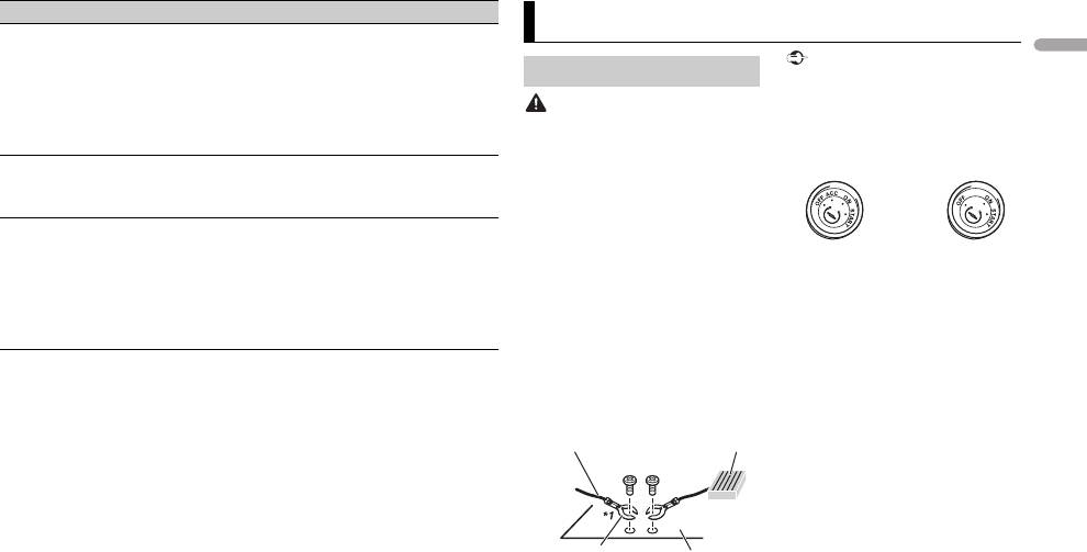
• The black cable is ground. When
installing this unit or power amp
(sold separately), make sure to
connect the ground wire first. Ensure
that the ground wire is properly
connected to metal parts of the car’s
body. The ground wire of the power
amp and the one of this unit or any
other device must be connected to
the car separately with different
screws. If the screw for the ground
wire loosens or falls out, it could
result in fire, generation of smoke or
malfunction.
Important
Connections/Installation
Connections
• When installing this unit in a vehicle
without an ACC (accessory) position
on the ignition switch, failure to
connect the red cable to the terminal
that detects operation of the ignition
key may result in battery drain.
• Use of this unit in conditions other
than the following could result in fire
or malfunction.
– Vehicles with a 12-volt battery and
negative grounding.
– When speaker output is used by 4
channels, use speakers over 50 W
(maximum input power) and
between 4 Ω to 8 Ω (impedance
value). Do not use 1 Ω to 3 Ω
speakers for this unit.
– When rear speaker output is used
by 2 Ω of subwoofer, use speakers
over 70 W (maximum input power).
* Please refer to connection for a
connection method.
• To prevent a short-circuit,
overheating or malfunction, be sure
to follow the directions below.
– Disconnect the negative terminal
of the battery before installation.
–Secure the wiring with cable
clamps or adhesive tape. Wrap
Ground wire POWER AMP
Other devices
Metal parts of
(Another electronic
car’s body
device in the car)
*1 Not supplied for this unit
ACC position No ACC position
127075007029_artwork.book Page 13 Tuesday, May 24, 2016 7:48 PM
X:\print\Pioneer\ODM\127075007029(B6_Horizon)\020Chapter_EN.fm
adhesive tape around wiring that
the power terminal of the auto
Green/black
comes into contact with metal
antenna. Doing so may result in
Violet
parts to protect the wiring.
battery drain or a malfunction.
Violet/black
–Place all cables away from moving
• The black cable is ground. Ground
Black (chassis ground)
parts, such as the shift lever and
cables for this unit and other
Connect to a clean, paint-free
seat rails.
equipment (especially, high-current
metal location.
–Place all cables away from hot
products such as power amps) must
Yellow
places, such as near the heater
be wired separately. If they are not,
Connect to the constant 12 V
outlet.
an accidental detachment may result
supply terminal.
– Do not connect the yellow cable to
in a fire or malfunction.
Red
the battery by passing it through
Connect to terminal controlled by
the hole to the engine
This unit
the ignition switch (12 V DC).
compartment.
Blue/white
Perform these connections when
–Cover any disconnected cable
Connect to the system control
using a subwoofer without the
connectors with insulating tape.
terminal of the power amp or auto-
optional amplifier.
–Do not shorten any cables.
antenna relay control terminal
–Never cut the insulation of the
(max. 300 mA 12 V DC).
power cable of this unit in order to
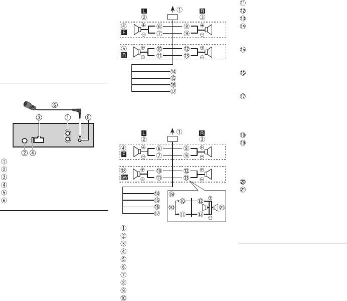
Subwoofer (4 Ω)
share the power with other devices.
When using a subwoofer of 2 Ω, be
The current capacity of the cable is
sure to connect the subwoofer to
limited.
the violet and violet/black leads of
Rear output or subwoofer output
–Use a fuse of the rating prescribed.
this unit. Do not connect anything
Antenna input
–Never wire the negative speaker
to the green and green/black leads.
Power cord input
cable directly to ground.
Not used.
Fuse (10 A)
–Never band together negative
Subwoofer (4 Ω) × 2
Microphone input
cables of multiple speakers.
Microphone (3 m)
• When this unit is on, control signals
are sent through the blue/white
Power cord
cable. Connect this cable to the
Perform these connections when not
system remote control of an external
To power cord input
connecting a rear speaker lead to a
power amp or the vehicle’s auto-
Left
subwoofer.
antenna relay control terminal (max.
Right
300mA 12 V DC). If the vehicle is
Front speaker
equipped with a glass antenna,
Rear speaker
connect it to the antenna booster
White
power supply terminal.
White/black
• Never connect the blue/white cable
Gray
to the power terminal of an external
Gray/black
power amp. Also, never connect it to
Green
14
En
127075007029(B6_Horizon)
MVH-29BT
NOTE
127075007029_artwork.book Page 14 Tuesday, May 24, 2016 7:48 PM
Change the initial menu of this unit.
Refer to [SP-P/O MODE] (page 6). The
subwoofer output of this unit is
monaural.
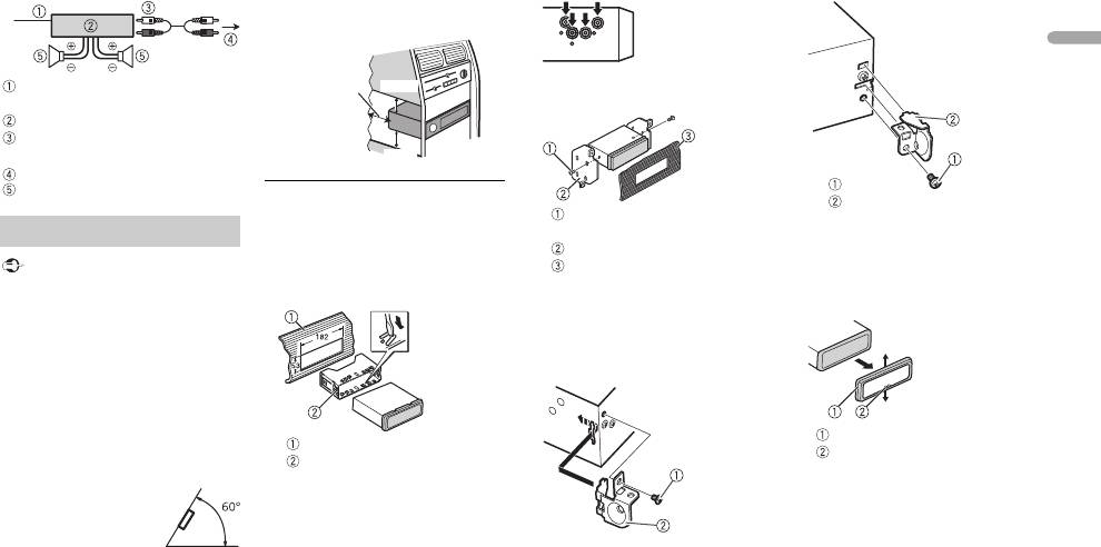
Power amp (sold separately)
Perform these connections when
using the optional amplifier.
X:\print\Pioneer\ODM\127075007029(B6_Horizon)\020Chapter_EN.fm
En
15
127075007029(B6_Horizon)
MVH-29BT
English
System remote control
Connect to blue/white cable.
Power amp (sold separately)
Connect with RCA cables (sold
separately)
To rear output or subwoofer output
Rear speaker or subwoofer
Important
loose cables so they are not blocking
the vents.
DIN mount installation
1 Insert the supplied mounting
Installation
sleeve into the dashboard.
2 Secure the mounting sleeve by
using a screwdriver to bend the
• Check all connections and systems
metal tabs (90°) into place.
before final installation.
• Do not use unauthorized parts as
this may cause malfunctions.
• Consult your dealer if installation
requires drilling of holes or other
modifications to the vehicle.
• Do not install this unit where:
–it may interfere with operation of
the vehicle.
Dashboard
–it may cause injury to a passenger
Mounting sleeve
as a result of a sudden stop.
• Make sure that the unit is
• Optimum
installed securely in place. An
performance is
unstable installation may cause
obtained when the
skipping or other malfunctions.
unit is installed at an
angle of less than 60°.
When not using the supplied
• When installing, to ensure proper
mounting sleeve
heat dispersal when using this unit,
1 Line up the holes on the
make sure you leave ample space
mounting bracket with the holes
behind the rear panel and wrap any
on the sides of the unit to attach
the bracket.
Leave ample
5 cm
space
5 cm
2 Screw in one screw on each side to
hold the unit in place.
Tapping screw (φ5 mm × 9 mm,
not supplied with product)
Removing the unit (installed
Mounting bracket
with the supplied mounting
Dashboard or console
sleeve)
Using the included bracket
1 Remove the trim ring.
Check to make sure that the included
bracket matches your particular
model of vehicle and then attach it to
the unit as shown below.
Trim ring
Notched tab
• Releasing the front panel allows
easier access to the trim ring.
• When reattaching the trim ring,
point the side with the notched
tab down.
2 Insert the supplied extraction
keys into both sides of the unit
until they click into place.
3 Pull the unit out of the dashboard.
Screw
Bracket
127075007029_artwork.book Page 15 Tuesday, May 24, 2016 7:48 PM
X:\print\Pioneer\ODM\127075007029(B6_Horizon)\020Chapter_EN.fm
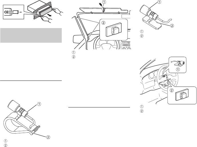
Installing the
microphone
• Install the microphone in a place
where its direction and distance
from the driver make it easiest to
pick up the driver’s voice.
• Be sure to turn off (ACC OFF) the
product before connecting the
microphone.
Mounting on the sun visor
Install the microphone on the sun
visor when it is in the up position. It
1 Fit the microphone into the
cannot recognize the driver’s voice
microphone clip.
if the sun visor is in the down
position.
Installation on the steering
column
1 Fit the microphone into the
Microphone Base.
2 Mount the microphone clip to the
sun visor.
16
En
127075007029(B6_Horizon)
MVH-29BT
Microphone
Microphone clip
Microphone clip
Clamps
Use separately sold clamps to
secure the lead where
necessary inside the vehicle.
2 Attach the microphone on the
steering column.
3 Keeping it away from the steering
wheel.
Microphone
Microphone base with
double-sided tape
Microphone Base
Clamps
Use separately sold clamps to
secure the lead where
necessary inside the vehicle.
127075007029_artwork.book Page 16 Tuesday, May 24, 2016 7:48 PM


