Pioneer MVH-07UB: Connections/Installation
Connections/Installation: Pioneer MVH-07UB
Connections/Installation
– Never band together negative cables of
Connections
m
ultiple speakers.
• When
this unit is on, control signals are
Important
sent through the blue/white cable.
English
• When i
nstalling this unit in a vehicle
Connect this cable to the system remote
without an ACC (accessory) position on
control of an external power amp or the
the ignition switch, failure to connect the
vehicle’s auto-antenna relay control
red cable to the terminal that detects
terminal (max. 300mA 12 V DC). If the
operation of the ignition key may result
vehicle is equipped with a glass antenna,
in battery drain.
connect it to the antenna booster power
supply terminal.
• Nev
er connect the blue/white cable to
the power terminal of an external power
amp. Also, never connect it to the power
terminal of the auto antenna. Doing so
• T
o prevent a short-circuit, overheating or
may result in battery drain or a
malfunction, be sure to follow the
malfunction.
directions below.
–Disconnect the negative terminal of the
This unit
bat
tery before installation.
–Secure the wiring with cable clamps or
ad
hesive tape. Wrap adhesive tape
around wiring that comes into contact
with metal parts to protect the wiring.
– Place all cables away from moving parts,
su
ch as the shift lever and seat rails.
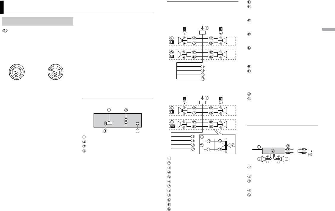
Power cord input
–Place all cables away
from hot places,
Rear output or subwoofer output
such as near the heater outlet.
Antenna input
– Do not connect the yellow cable to the
Fuse (10 A)
bat
tery by passing it through the hole
to the engine compartment.
–Cover any disconnected cable
co
nnectors with insulating tape.
– Do not shorten any cables.
–Never cut the insulation of the power
cabl
e of this unit in order to share the
power with other devices. The current
capacity of the cable is limited.
–Use a fuse of the rating prescribed.
–Never wire the negative speaker cable
di
rectly to ground.
9En
ACC position No ACC position
Violet/black
Power cord
Black (chassis ground)
Perform these connections when not
Connect to a clean, paint-free metal
connecting a rear speaker lead to a
lo
cation.
subwoofer.
Yellow
Connect to the constant 12 V supply
te
rminal.
Red
Connect to terminal controlled by the
ign
ition switch (12 V DC).
Blue/white
Connect to the system control terminal
of
the power amp or auto-antenna relay
control terminal (max. 300 mA 12 V DC).
Subwoofer (4 Ω)
When using a subwoofer of 70 W (2 Ω),
be sure to connect the subwoofer to the
viol
et and violet/black leads of this unit.
Perform these connections when using a
Do not connect anything to the green
s
ubwoofer without the optional amplifier.
and green/black leads.
Not used.
Subwoofer (4 Ω) × 2
NOTE
Change the initial menu of this unit. Refer
t
o [SP-P/O MODE] (page 5). The subwoofer
output of this unit is monaural.
Power amp (sold separately)
Perform these connections when using the
optional amplifier.
To power cord input
Left
Right
System remote control
Front speaker
Connect to blue/white cable.
Rear speaker
Power amp (sold separately)
White
Connect with RCA cables (sold
White/black
separately)
Gray
To rear output or subwoofer output
Gray/black
Rear speaker or subwoofer
Green
Green/black
Violet
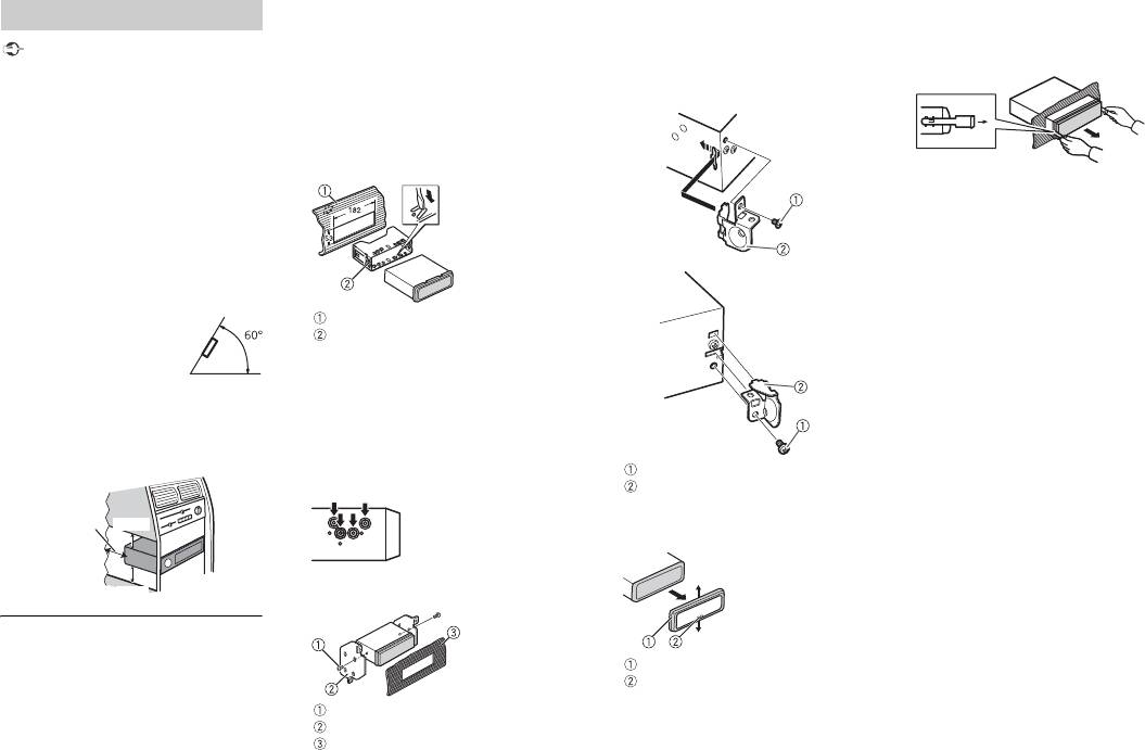
DIN Front-mount
Installation
1 Insert the mounting sleeve into the
Important
dashboard.
For installation in shallow spaces, use
• C
heck all connections and systems before
th
e supplied mounting sleeve. If there is
final installation.
enough space, use the mounting sleeve
• D
o not use unauthorized parts as this
that came with the vehicle.
may cause malfunctions.
• C
onsult your dealer if installation requires
2 Secure the mounting sleeve by using a
drilling of holes or other modifications to
screwdriver to bend the metal tabs
the vehicle.
(90°) into place.
• D
o not install this unit where:
–it may interfere with operation of the
ve
hicle.
–it may cause injury to a passenger as a
resu
lt of a sudden stop.
• T
he semiconductor laser will be damaged
if it overheats. Install this unit away from
hot places such as near the heater outlet.
• Opti
mum performance is
Dashboard
obtained when the unit is
Mounting sleeve
installed at an angle of less
Make sure that the unit is installed
than 60°.
s
ecurely in place. An unstable
• W
hen installing, to ensure proper heat
installation may cause skipping or other
dispersal when using this unit, make sure
malfunctions.
you leave ample space behind the rear
DIN Rear-mount
panel and wrap any loose cables so they
1 Line up the holes on the mounting
are not blocking the vents.
bracket with the holes on the sides of
the unit to attach the bracket.
2 Screw in one screw on each side to
hold the unit in place.
DIN front/rear mount
This unit can be properly installed using
either front-mount or rear-mount
installation.
Use commercially available parts when
Tapping screw (5 mm × 8 mm)
ins
talling.
Mounting bracket
Dashboard or console
10En
Leave ample
5 cm
space
5 cm
Using the included bracket
2 Insert the supplied extraction keys
You can also use the included bracket to
into both sides of the unit until they
mount the unit. Check to make sure that
click into place.
the included bracket matches your
3 Pull the unit out of the dashboard.
particular model of vehicle and then attach
it to the unit as shown below.
Screw
Bracket
Removing the unit
1 Remove the trim ring.
Trim ring
Notched tab
• R
eleasing the front panel allows easier
access to the trim ring.
• W
hen reattaching the trim ring, point
the side with the notched tab down.


