Karcher Balayeuse KM 90-60 R G: Shutdown Maintenance and care
Shutdown Maintenance and care: Karcher Balayeuse KM 90-60 R G
-
7
or unloading the machine, it may only be
operated on gradients of max. 18%.
Danger
Risk of injury and damage! Note the weight
of the appliance in case of storage.
If the sweeper is going to be out of service
for a longer time period, observe the follow-
ing points:
Park the sweeper on an even surface.
Fill fuel tank and close fuel cock.
Change engine oil.
Set programme switch to step 1 (driv-
ing). The roller brush and side brushes
are raised to prevent the bristles being
damaged.
Turn ignition key to "0" and remove it.
Unscrew spark plugs and pour approx.
3 cm
3
of oil into the spark plug holes.
Crank the engine several times before
replacing the spark plug. Screw in the
spark plug.
Lock the sweeper to ensure that it does
not roll off.
Clean the inside and outside of the
sweeper.
Park the machine in a safe and dry
place.
Disconnect battery.
Charge battery approx. every 2 months.
First switch off the appliance, remove
the key and disconnect the battery be-
fore performing any cleaning or mainte-
nance tasks on the appliance, replacing
parts or switching over to another func-
tion.
Always disconnect the battery when
working on the electrics.
– Maintenance work may only be carried
out by approved customer service out-
lets or experts in this field who are famil-
iar with the respective safety
regulations.
– Mobile appliances used for commercial
purposes are subject to safety inspec-
tions according to VDE 0701.
– Use only roller brushes/ side-brushes
that are provided with the appliance or
specified in the Operations Manual.
The use of other roller brushes/ side-
brushes can affect the safety of the ap-
pliance.
Caution
Risk of damage! Do not clean the appliance
with a water hose or high-pressure water
jet (danger of short circuits or other dam-
age).
Danger
Risk of injury! Wear dust mask and protec-
tive goggles.
Open the device hood.
Clean machine with a cloth.
Blow through machine with com-
pressed air.
Close cover.
Clean the machine with a damp cloth
which has been soaked in mild deter-
gent.
Note:
Do not use aggressive cleaning
agents.
Note:
The elapsed-time counter shows the
timing of the maintenance intervals.
Daily maintenance:
Check engine oil level.
Check axle drive oil level.
Check tyre pressure.
Check function of all operator control el-
ements.
Weekly maintenance:
Check petrol pipes for leaks.
Check air filter.
Check for smooth running of the Bow-
den cables and the moveable parts
Check the sealing strips in the sweep-
ing area for position and wear.
Check dust filter and clean filter box, if
required.
Maintenance to be carried out every 100
operating hours:
Check petrol pipes for leaks.
Change engine oil (initial change after
20 operating hours).
Check spark plug.
Check function of seat contact switch.
Check battery acid level.
Check tension, wear and function of
drive belts (V-belt and circular belt).
Check the 4 rubber buffers on the drive
axle.
Maintenance following wear:
Replace sealing strips.
Replace roller brush.
Replace side brush.
Note:
For description, see section on Main-
tenance work.
Note:
Where maintenance is carried out by
the customer, all service and maintenance
work must be undertaken by a qualified
specialist. If required, a specialised Archer
dealer may be contacted at any time.
Maintenance to be carried out after 20 op-
erating hours:
Carry out initial inspection.
Maintenance to be carried out every 100
operating hours
Maintenance to be carried out every 200
operating hours
Maintenance to be carried out every 300
operating hours
Note:
In order to safeguard warranty
claims, all service and maintenance work
during the warranty period must be carried
out by the authorised Kärcher Customer
Service in accordance with the mainte-
nance booklet.
Preparation:
Park the sweeper on an even surface.
Turn ignition key to "0" and remove it.
Danger
Risk of injury!
The engine requires approx. 3-4 seconds
to come to a standstill once it has been
switched off. During this time, stay well
clear of the working area.
– Allow the machine sufficient time to cool
down before carrying out any mainte-
nance and repair work.
– Do not touch any hot parts, such as the
drive motor and exhaust system.
Please observe the following warning notes
when handling batteries:
Storage
Shutdown Maintenance and care
General notes
Cleaning
Cleaning the inside of the machine
External cleaning of the appliance
Maintenance intervals
Maintenance by the customer
Maintenance by Customer Service
Maintenance Works
General notes on safety
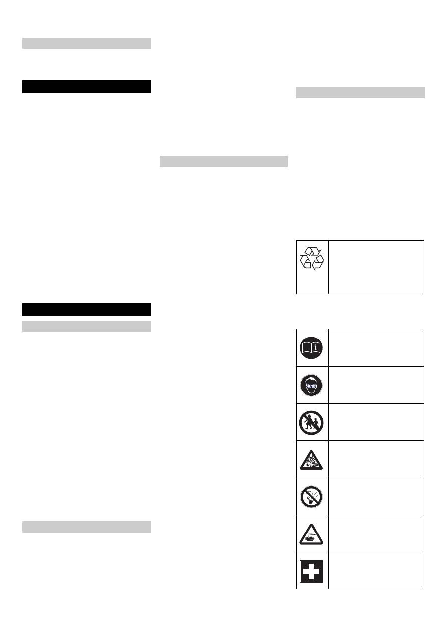
Please do not release engine
oil, fuel oil, diesel and petrol
into the environment Protect
the ground and dispose of
used oil in an environmentally-
clean manner.
Safety notes regarding the batteries
Observe the directions on the
battery, in the instructions for
use and in the vehicle operat-
ing instructions!
Wear an eye shield!
Keep away children from acid
and batteries!
Risk of explosion!
Fire, sparks, open light, and
smoking not allowed!
Danger of causticization!
First aid!
23 EN
-
8
Danger
Risk of explosion! Do not put tools or similar
on the battery, i.e. on the terminal poles
and cell connectors.
Danger
Risk of injury! Ensure that wounds never
come into contact with lead. Always clean
your hands after having worked with batter-
ies.
Danger
Risk of fire and explosion!
–
Smoking and naked flames are strictly
prohibited.
–
Rooms where batteries are charged
must have good ventilation because
highly explosive gas is emitted during
charging.
Danger
Danger of causticization!
–
Rinse thoroughly with lots of clear water
if acid gets into the eye or comes in con-
tact with the skin.
–
Then consult a doctor immediately.
–
Wash off the acid If it comes in contact
with the clothes.
You must fill the enclosed battery with the
acid provided before you install it.
Danger
Risk of explosion. Ensure proper ventila-
tion.
Risk of injury, risk of explosion. Observe
the safety instructions for handling batter-
ies in the separate operating instructions of
the unit.
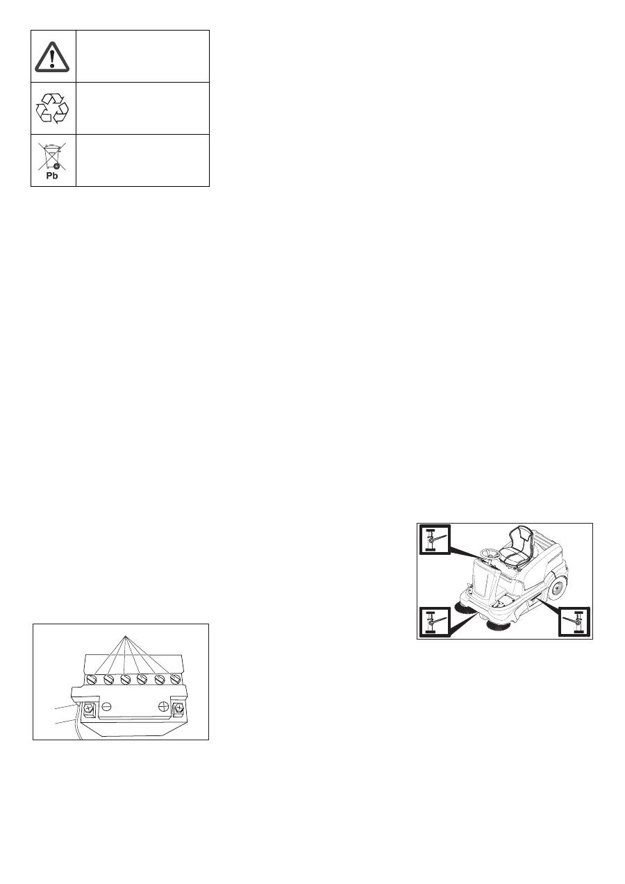
1 Cell cap
2 Hose nipple
3 Battery overflow hose
Open the front panel.
Remove the battery overflow hose.
Remove the battery from its holder.
Unscrew the cell caps.
Fill the enclosed acid into the cells up to
„UPPER LEVEL“ mark.
Screw in the cell caps.
Remove front panel.
Insert battery in battery mount.
Connect pole terminal (red cable) to
positive pole (+).
Connect pole terminal to negative pole
(-).
Note:
Check that the battery pole and pole
terminals are adequately protected with
pole grease.
Danger
Risk of injury! Comply with safety regula-
tions on the handling of batteries. Observe
the directions provided by the manufacturer
of the charger.
Danger
Charge the battery only with an appropriate
charger.
Disconnect battery.
Unscrew all cell caps.
Connect positive terminal cable from
the charger to the positive pole connec-
tion on the battery.
Connect negative terminal cable from
the charger to the negative pole con-
nection on the battery.
Plug in mains connector and switch on
charger.
Note:
When the battery is charged, first re-
move the charger from the mains and then
disconnect it from the battery.
Screw in cell caps.
Remove front panel.
Disconnect pole terminal to negative
pole (-).
Disconnect pole terminal to positive
pole (-).
Remove the battery from the battery
holder.
Dispose of the used battery according
to the local provisions.
Caution
Regularly check the fluid level in acid-filled
batteries.
– The acid in a fully charged battery has a
specific weight of 1.28 kg/l at a temper-
ature of 20 °C.
– The acid in a partially discharged bat-
tery has a specific weight between 1.00
and 1.28 kg/l.
– The specific weight of the acid must be
uniform in all cells.
Unscrew all cell caps.
Take a sample from each cell using the
acid tester.
Put the acid sample back into the same
cell.
Where fluid level is too low, top up cells
to the mark provided with distilled wa-
ter.
Charge battery.
Screw in cell caps.
Park the sweeper on an even surface.
Connect air pressure testing device to
tyre valve.
Check air pressure and adjust if re-
quired.
Set air pressure for the front tyre to 4
bar.
Set air pressure for the rear tyres to 4
bar.
Danger
Risk of injury!
Park the sweeper on an even surface.
Remove ignition key.
When carrying out repairs on public
highways, wear warning clothing when
working close to passing traffic.
Check stability of ground. Also secure
the machine with wheel chock(s) to pre-
vent it rolling away.
Check tyres
Check tyre contact face for foreign ob-
jects.
Remove objects found.
Use suitable, commercially available
materials to carry out tyre repairs.
Note:
Observe the manufacturer's recom-
mendations. The journey may be resumed
providing that the directions supplied by the
product manufacturer have been observed.
The tyre/wheel change should nonetheless
be carried out as soon as possible.
Raise slightly the waste container on
the appropriate side and pull it out.
Position vehicle jack at the appropriate
mounting point for the front or rear
wheel.
Raise machine using vehicle jack.
Remove the fastening disc (only rear
wheel).
Remove wheel.
Mount spare wheel.
Install the fastening disc (only rear
wheel).
Lower machine using vehicle jack.
Push in the waste container and lock it.
Note:
Use a suitable commercially availa-
ble vehicle jack.
Warning note!
Disposal!
Do not throw the battery in the
dustbin!
Fill battery with battery acid
1
2
3
Installing and connecting the battery
Charging battery
Remove the battery
Check fluid level in the battery and ad-
just if required
Check the tyre pressure
Replacing wheel
24 EN
-
9
Danger
Risk of burns!
Allow engine to cool down.
Wait for at least 5 minutes after switch-
ing off the engine before checking the
engine oil fill level.
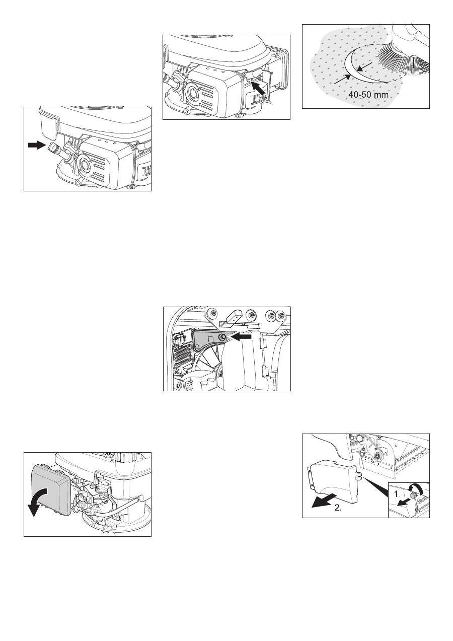
Open the device hood.
Unscrew and withdraw oil dipstick.
Wipe off oil dipstick and screw it in.
Unscrew and withdraw oil dipstick.
Read the value of the oil level.
– The oil level must lie between “MIN“
and “MAX“ marking.
– Add motor oil if the oil level is below the
"MIN" marking.
– Do not fill oil above the "MAX" marking.
Fill motor oil into the oil fill neck.
Oil grade: see Technical Data
Reinsert the oil dipstick.
Wait at least 5 minutes.
Check engine oil level.
Danger
Risk of burns due to hot oil!
Allow engine to cool down.
Open the device hood.
Unscrew and withdraw oil dipstick.
Draw off engine oil via the oil filler neck
using 6.491-538 oil-change pump.
Fill motor oil into the oil fill neck.
Oil grade: see Technical Data
Reinsert the oil dipstick.
Wait at least 5 minutes.
Check engine oil level.
Remove covering lid.
Take out the filter inlay.
Insert a new filter insert.
The filter lamella must point into the di-
rection of the locking cap.
Attach the locking cap.
Remove spark-plug connector.
Unscrew and clean spark plug.
Screw in cleaned or new spark plug.
Push on spark-plug connector.
Open the device hood.
Close the fuel supply.
Turn the rotating knob perpendicular to
the fuel tap.
Open fuel filler cap.
Draw off fuel using suitable pump.
(1) Checking fill level
Open the device hood.
Locking screw of the balancing contain-
er.
Check the fill level in the header tank.
Note:
The oil level must be 3 mm above the
container base.
Caution
This inspection may only be carried out
when the engine is cold.
(2) Adjusting fill level
Locking screw of the balancing contain-
er.
If required, top up oil carefully.
Close container.
Oil grade: see Technical Data
Check tyre pressure.
The side-brushes lift up.
Drive sweeper on to a smooth, even
surface covered with a visible layer of
dust or chalk.
Lower side-brushes and allow them to
briefly rotate.
The side-brushes lift up.
Drive machine backwards.
Park the sweeper on an even surface.
Check sweeping mirror.
The width of the sweeping track should lie
between 40-50 mm.
Note:
The side brush floating mounting ad-
justs the sweeping track as the bristles
wear down. The side brush must be re-
placed if it becomes too worn.
Park the sweeper on an even surface.
Set programme switch to step 1 (driv-
ing). Side brushes lift up.
Turn ignition key to "0" and remove it.
Loosen 3 fastening screws on the un-
derside.
Clip side brush on to driver and screw
on.
Park the sweeper on an even surface.
Set programme switch to step 1 (driv-
ing). Roller brush is raised.
Turn ignition key to "0" and remove it.
Secure the machine with wheel
chock(s) to prevent it from rolling away.
Remove belts or cords from roller
brush.
Replacement is due if a visible deteriora-
tion in sweeping performance caused by
bristle wear is evident.
Park the sweeper on an even surface.
Set programme switch to step 1 (driv-
ing). Roller brush is raised.
Turn ignition key to "0" and remove it.
Secure the machine with wheel
chock(s) to prevent it from rolling away.
Raise slightly the waste container on
the left side and pull it out.
Loosen the fastening screw on the left
side-panel.
Remove side panel.
Check engine oil level and top up, if re-
quired
Change the engine oil
Change the air filter
Clean or replace the spark plug
Empty fuel tank
Check and adjust fill level of hydraulic
oil
Checking the sweeping mirror of the
side-brushes
Replacing side brush
Checking roller brush
Replacing roller brush
25 EN
-
10
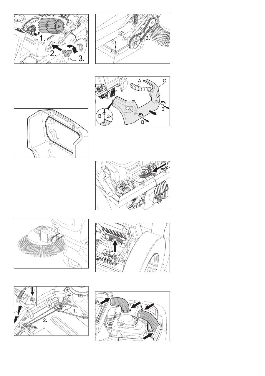
Hook the draw spring out.
A Fastening screw of the under-pressure
can
B Fastening nut of the bulk waste flap
C Screw of the roller brush crank
Unscrew the fastening screws of the
vacuum socket and release the lever.
Turn the fastening nut of the bulk waste
flap and unhook the bulk waste flap.
Unscrew and withdraw bolt on the roller
brush swinging arm.
Push the roller brush cover backwards
and remove it.
Pull out roller brush.
Installation position of roller brush in direc-
tion of travel
Push new roller brush into the roller
brush housing and onto the drive pin.
Note:
When installing the new roller brush,
ensure correct positioning of the bristle as-
sembly.
Position roller brush cover.
Fit the fastening screws and nuts.
Hook the draw spring in.
Screw on side panel.
Push in the waste containers on both
the sides and lock them.
Set programme switch to step 1 (driv-
ing). The side brush and roller brush are
raised.
Drive sweeper on to a smooth, even
surface covered with a visible layer of
dust or chalk.
Lower roller brush and allow it to briefly
rotate.
Raise roller brush.
Press pedal which raises bulk waste
flap and keep pressed.
Drive machine backwards.
The sweeping track should have an even
rectangular shape which is between 50 and
70 mm wide.
Note:
The side brush floating mounting of
the roller brush adjusts the sweeping track
as the bristles wear down. The roller brush
must be replaced if it becomes too worn.
Park the sweeper on an even surface.
Set programme switch to step 1 (driv-
ing). Roller brush is raised.
Turn ignition key to "0" and remove it.
Secure the machine with wheel
chock(s) to prevent it from rolling away.
Raise slightly the waste containers on
both sides and pull them out.
Open the fastening screws of the side
panels on both sides.
Remove side panels.
Front sealing strip
Loosen retaining nuts for the front seal-
ing strip (1) slightly (to replace, un-
screw).
Screw on new sealing strip without fully
tightening the nuts.
Adjust sealing strip.
Set the distance between the sealing
strip and the floor so that the bottom
edge trails behind at a distance of be-
tween 10-15 mm.
Tighten nuts.
Rubber strip
If worn, replace.
Unscrew retaining nuts for the rubber
strip (2).
Screw on new rubber strip.
Rear sealing strip
Set the distance between the sealing
strip and the floor so that the bottom
edge trails behind at a distance of be-
tween 5 and 10 mm.
If worn, replace.
Unscrew retaining nuts for rear sealing
strip (3).
Screw on new sealing strip.
Side sealing strips
Slightly loosen retaining nuts for the
side sealing strip (to replace, unscrew).
Screw on new sealing strip without fully
tightening the nuts.
To set the floor clearance, insert a
sheet with a thickness of between 1 and
3 mm under the sealing strip.
Adjust sealing strip.
Tighten nuts.
Screw on side panels.
Push in the waste containers on both
the sides and lock them.
몇
Warning
Empty waste container before replacing
dust filter. Wear a dust mask when working
around the dust filter. Observe safety regu-
lations on the handling of fine particulate
material.
Open the device hood.
Loosen the fastening screws.
Press the filter holder upwards and re-
move it.
Remove the lamella filter.
Insert new filter.
Check the sweeping mirror of the
sweeping roller
Adjusting and replacing sealing strips
Replacing dust filter
26 EN
-
11
Make sure driver engages with holes on
drive side.
Insert the filter holder and press down-
wards.
Tighten the fastening screws.
Note:
Make sure when installing the new
filter that the fins are not damaged.
Lift filter case seal out of groove in the
cover.
Insert new seal.
Danger
The engine requires approx. 3-4 seconds
to come to a standstill once it has been
switched off. During this time, stay well
clear of the working area.
Turn ignition key to "0" and remove it.
Open the device hood.
Check tension of circular belt of the
side-brush; also check for wear or dam-
age.
Check tension, wear and damages on
the V-belt of the sweep roller drive.
Tighten the V-belt at the screw if neces-
sary.
Check tension, wear and damages on
the V-belt of the sweep roller drive.
A Exhaust hose
B Fastening screws
C Tail panel
Loosen exhaust hose.
Unscrew locking screws.
Remove the tail panel.
Check tension of V-belt of axle drives;
also check for wear or damage.
Check tension of rib belt of generator;
also check for wear or damage.
Check hoses of suction blower for ab-
sence of leakness.
The drive control/electronic system is in-
stalled behind the front panel. To replace a
fuse, the front panel must be removed.
Loosen the front panel screws.
Note:
The assignment of fuses is indicated
on the inside of the panel. Only use fuses
with identical safety ratings.
Replace defective fuses.
Replace front panel.
Replacing filter case seal
Checking drive belt
Check suction blower
Replacing fuses of drive control/ elec-
tronic system
27 EN
Оглавление
- Inhaltsverzeichnis
- Funktion Bestimmungsgemäße Ver- wendung
- Bedien- und Funktionselemente
- Vor Inbetriebnahme
- Stilllegung Pflege und Wartung
- Hilfe bei Störungen
- Technische Daten
- Zubehör
- Contents
- Function Proper use
- Operating and Functional Elements
- Before Startup
- Shutdown Maintenance and care
- Troubleshooting
- Technical specifications
- Accessories
- Table des matières
- Fonction Utilisation conforme
- Eléments de commande et de fonction
- Avant la mise en service
- Remisage Entretien et maintenance
- Assistance en cas de panne
- Caractéristiques techniques
- Accessoires
- Indice
- Funzione Uso conforme a destinazione
- Elementi di comando e di funzione
- Prima della messa in funzione
- Fermo dell'impianto Cura e manutenzione
- Guida alla risoluzione dei guasti
- Dati tecnici
- Accessori
- Inhoudsopgave
- Functie Reglementair gebruik
- Elementen voor de bediening en de functies
- Voor de inbedrijfstelling
- Stillegging Onderhoud
- Hulp bij storingen
- Technische gegevens
- Toebehoren
- Índice de contenidos
- Función Uso previsto
- Elementos de operación y funcionamiento
- Antes de la puesta en marcha
- Parada Cuidados y mantenimiento
- Ayuda en caso de avería
- Datos técnicos
- Accesorios
- Índice
- Funcionamento Utilização conforme o fim a que se destina a máquina
- Elementos de comando e de funcionamento
- Antes de colocar em funcio- namento
- Desactivação da máquina Conservação e manutenção
- Ajuda em caso de avarias
- Dados técnicos
- Acessórios
- Indholdsfortegnelse
- Funktion Bestemmelsesmæssig an- vendelse
- Betjenings- og funktionselementer
- Inden ibrugtagning
- Afbrydning/nedlæggelse
- Pleje og vedligeholdelse
- Hjælp ved fejl
- Tekniske data
- Tilbehør
- Innholdsfortegnelse
- Funksjon Forskriftsmessig bruk
- Betjenings- og funksjonelementer
- Før den tas i bruk
- Sette bort
- Pleie og vedlikehold
- Feilretting
- Tekniske data
- Tilbehør
- Innehållsförteckning
- Funktion Ändamålsenlig användning
- Manövrerings- och funktionselement
- Före ibruktagande
- Nedstängning
- Skötsel och underhåll
- Åtgärder vid störningar
- Tekniska data
- Tillbehör
- Sisällysluettelo
- Toiminta Käyttötarkoitus
- Ohjaus- ja käyttölaitteet
- Ennen käyttöönottoa
- Seisonta-aika Hoito ja huolto
- Häiriöapu
- Tekniset tiedot
- Tarvikkeet
- Πίνακας περιεχομένων
- Λειτουργία Χρήση σύμφωνα με τους κανονισμούς
- Στοιχεία χειρισμού και λειτουργίας
- Πριν τη θέση σε λειτουργία
- Διακοπή της λειτουργίας Φροντίδα και συντήρηση
- Αντιμετώπιση βλαβών
- Τεχνικά χαρακτηριστικά
- Εξαρτήματα
- İ çindekiler
- Fonksiyon Kurallara uygun kullan ı m
- Kullan ı m ve çal ı ş ma elemanlar ı
- Cihaz ı çal ı ş t ı rmaya ba ş lamadan önce
- Durdurma Koruma ve Bak ı m
- Ar ı zalarda yard ı m
- Teknik Bilgiler
- Aksesuar
- Оглавление
- Назначение Использование по назначению
- Описание элементов управления и рабочих узлов
- Перед началом работы
- Вывод из эксплуатации Уход и техническое обслуживание
- Помощь в случае неполадок
- Технические данные
- Принадлежности
- Tartalomjegyzék
- Funkció Rendeltetésszer ű használat
- Kezelési- és funkciós elemek
- Üzembevétel el ő tt
- Leállítás Ápolás és karbantartás
- Segítség üzemzavar esetén
- M ű szaki adatok
- Tartozékok
- Obsah
- Funkce Používání v souladu s ur č ením
- Ovládací a funk č ní prvky
- P ř ed uvedením do provozu
- Odstavení Ošet ř ování a údržba
- Pomoc p ř i poruchách
- Technické údaje
- P ř íslušenství
- Vsebinsko kazalo
- Delovanje Namenska uporaba
- Upravljalni in funkcijski elementi
- Pred zagonom
- Mirovanje naprave Nega in vzdrževanje
- Pomo č pri motnjah
- Tehni č ni podatki
- Pribor
- Spis tre ś ci
- Funkcja U ż ytkowanie zgodne z przeznaczeniem
- Elementy urz ą dzenia
- Przed pierwszym uruchomieniem
- Wy łą czenie z eksploatacji Czyszczenie i konserwacja
- Usuwanie usterek
- Dane techniczne
- Akcesoria
- Cuprins
- Func ţ ionarea Utilizarea corect ă
- Elemente de utilizare ş i func ţ ionale
- Înainte de punerea în func ţ iune
- Scoaterea din func ţ iune Îngrijirea ş i între ţ inerea
- Remedierea defec ţ iunilor
- Date tehnice
- Accesorii
- Obsah
- Funkcia Používanie výrobku v súlade s jeho ur č ením
- Ovládacie a funk č né prvky
- Pred uvedením do prevádzky
- Odstavenie Starostlivos ť a údržba
- Pomoc pri poruchách
- Technické údaje
- Príslušenstvo
- Pregled sadržaja
- Funkcija Namjensko korištenje
- Komandni i funkcijski elementi
- Prije prve uporabe
- Stavljanje ure đ aja van pogona Njega i održavanje
- Otklanjanje smetnji
- Tehni č ki podaci
- Pribor
- Pregled sadržaja
- Funkcija Namensko koriš ć enje
- Komandni i funkcioni elementi
- Pre upotrebe
- Stavljanje ure đ aja van pogona Nega i održavanje
- Otklanjanje smetnji
- Tehni č ki podaci
- Pribor
- Съдържание
- Функция Употреба по предназначение
- Обслужващи и функционални елементи
- Преди пускане в експлоатация
- Спиране от експлоатация Грижи и поддръжка
- Помощ при неизправности
- Технически данни
- Принадлежности
- Sisukord
- Funktsioon Sihipärane kasutamine
- Teenindus- ja funktsioonielemendid
- Enne seadme kasutuselevõttu
- Seismapanek Korrashoid ja tehnohooldus
- Abi häirete korral
- Tehnilised andmed
- Tarvikud
- Satura r ā d ī t ā js
- Darb ī ba Noteikumiem atbilstoša lietošana
- Vad ī bas un funkcijas elementi
- Pirms ekspluat ā cijas uzs ā kšanas
- Iekonserv ē šana Kopšana un tehnisk ā apkope
- Pal ī dz ī ba darb ī bas trauc ē jumu gad ī jum ā
- Tehniskie dati
- Piederumi
- Turinys
- Veikimas Naudojimas pagal paskirt į
- Valdymo ir funkciniai elementai
- Prieš pradedant naudoti
- Laikinas prietaiso nenaudojimas Prieži ū ra ir aptarnavimas
- Pagalba gedim ų atveju
- Techniniai duomenys
- Dalys
- Перелік
- Призначення Правильне застосування
- Елементи управління і функціональні вузли
- Перед початком роботи
- Зберігання Догляд та технічне обслуговування
- Допомога у випадку неполадок
- Технічні характеристики
- Аксесуари
