Karcher NT 70-2 Adv: инструкция
Раздел: Климатическое Оборудование
Тип: Воздушная Завеса
Инструкция к Воздушной Завесе Karcher NT 70-2 Adv
NT 70/1
NT 70/2
NT 70/2 Me
NT 70/3
Deutsch 5
English 11
Français 17
Italiano 23
Nederlands 29
Español 35
Português 41
Dansk 47
Norsk 53
Svenska 59
Suomi 65
Ελληνικά 71
Türkçe 77
Русский 83
Magyar 90
Čeština 96
Slovenščina 102
Polski 108
Româneşte 114
Slovenčina 120
Hrvatski 126
Srpski 132
Български 138
Eesti 144
Latviešu 150
Lietuviškai 156
Register and win!
Українська 162
www.kaercher.com
59659460 02/13
26
2
1
25
24
24
27
23
4
3
22
NT 70/3
NT 70/1
20
NT 70/2
20
5
19
21 20 19
18
17
6
7
16
8
14 10
911121315
2
4
1
2
“Click”
2x
3
3
A
B
1.
2.
2.
1.
E
F
C
D
4
Lesen Sie vor der ersten Benut-
Altgeräte enthalten wertvolle re-
zung Ihres Gerätes diese Origi-
cyclingfähige Materialien, die ei-
nalbetriebsanleitung, handeln Sie danach
ner Verwertung zugeführt
und bewahren Sie diese für späteren Ge-
werden sollten. Batterien, Öl
brauch oder für Nachbesitzer auf.
und ähnliche Stoffe dürfen nicht
– Vor erster Inbetriebnahme Sicherheits-
in die Umwelt gelangen. Bitte
hinweise Nr. 5.956-249 unbedingt le-
entsorgen Sie Altgeräte deshalb
sen!
über geeignete Sammelsyste-
– Bei Nichtbeachtung der Betriebsanlei-
me.
tung und der Sicherheitshinweise kön-
Hinweise zu Inhaltsstoffen (REACH)
nen Schäden am Gerät und Gefahren
Aktuelle Informationen zu Inhaltsstoffen fin-
für den Bediener und andere Personen
den Sie unter:
entstehen.
www.kaercher.de/REACH
– Bei Transportschaden sofort Händler
informieren.
Symbole in der Betriebsanlei-
tung
Inhaltsverzeichnis
Gefahr
Umweltschutz. . . . . . . . . . . DE . . .1
Für eine unmittelbar drohende Gefahr, die
Symbole in der Betriebsanlei-
zu schweren Körperverletzungen oder zum
tung . . . . . . . . . . . . . . . . . . DE . . .1
Tod führt.
Bestimmungsgemäße Verwen-
dung . . . . . . . . . . . . . . . . . . DE . . .1
몇 Warnung
Geräteelemente . . . . . . . . . DE . . .2
Für eine möglicherweise gefährliche Situa-
Inbetriebnahme . . . . . . . . . DE . . .2
tion, die zu schweren Körperverletzungen
Bedienung . . . . . . . . . . . . . DE . . .3
oder zum Tod führen könnte.
Transport . . . . . . . . . . . . . . DE . . .3
Vorsicht
Lagerung . . . . . . . . . . . . . . DE . . .4
Für eine möglicherweise gefährliche Situa-
Pflege und Wartung . . . . . . DE . . .4
tion, die zu leichten Verletzungen oder zu
Hilfe bei Störungen. . . . . . . DE . . .4
Sachschäden führen kann.
Garantie . . . . . . . . . . . . . . . DE . . .4
Bestimmungsgemäße Ver-
Zubehör und Ersatzteile . . . DE . . .5
wendung
EG-Konformitätserklärung . DE . . .5
Technische Daten. . . . . . . . DE . . .6
몇 Warnung
Das Gerät ist nicht für die Absaugung ge-
Umweltschutz
sundheitsschädlicher Stäube geeignet.
– Dieser Sauger ist zur Nass- und Tro-
Die Verpackungsmaterialien
ckenreinigung von Boden- und Wand-
sind recyclebar. Bitte werfen Sie
flächen bestimmt.
die Verpackungen nicht in den
– Dieses Gerät ist für den gewerblichen
Hausmüll, sondern führen Sie
und industriellen Gebrauch geeignet,
diese einer Wiederverwertung
z.B. in Werkstätten, Industriebetrieben,
zu.
Schulen und Hotels.
– Die Raumtemperatur darf 40 °C nicht
überschreiten.
– Das Gerät darf mit Zuladung maximal
100 kg wiegen.
– 1
5DE

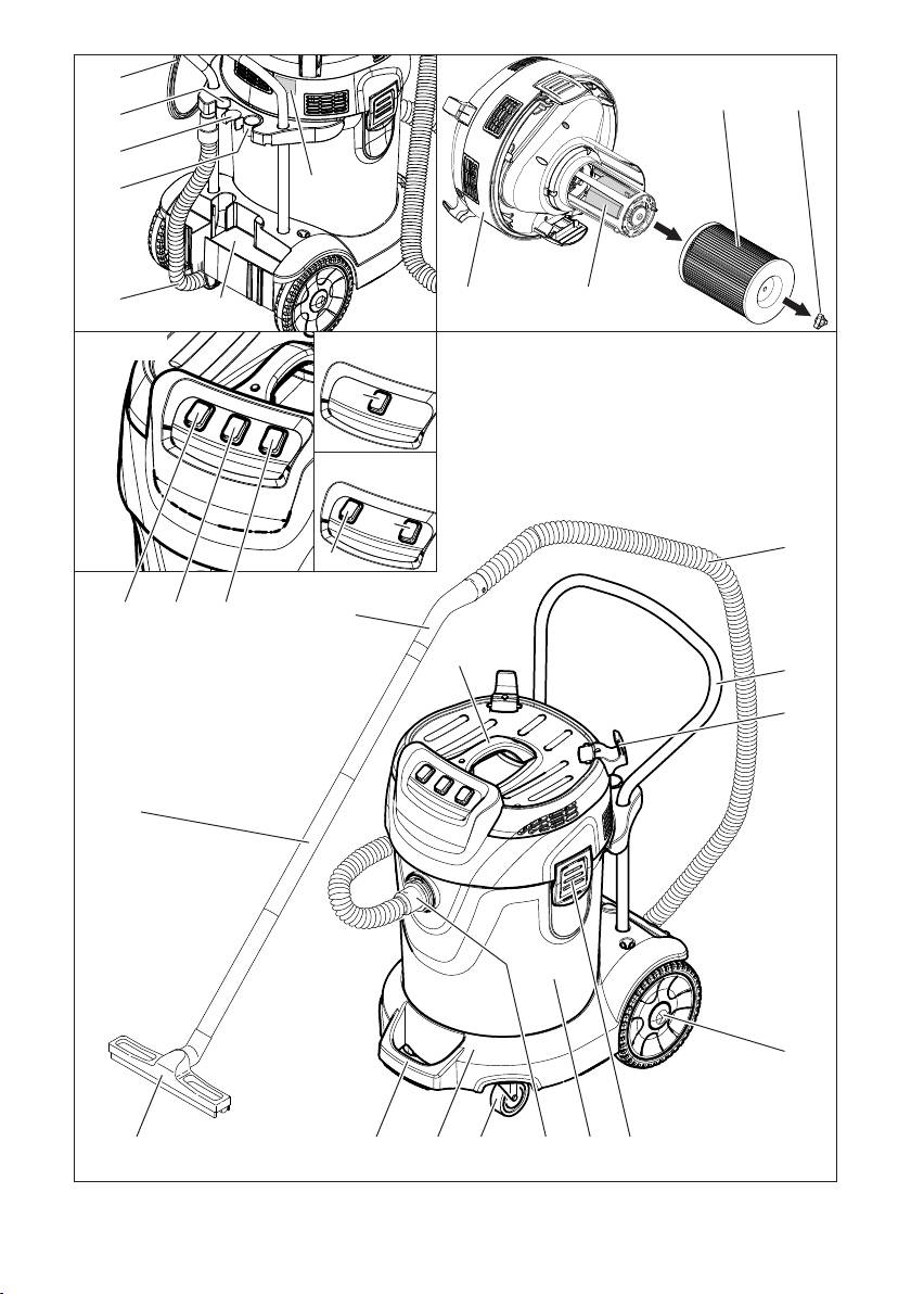
Geräteelemente
Trockensaugen
1 Sternschraube
Vorsicht
2 Patronenfilter
Beim Saugen darf niemals der Patronenfil-
3 Mechanischer Überlaufschutz
ter entfernt werden.
– Beim Aufsaugen von Feinstaub kann
4 Saugkopf
zusätzlich eine Papierfiltertüte oder ein
5 Saugschlauch
Membranfilter (Sonderzubehör) ver-
6 Schubbügel
wendet werden.
7 Kabelhaken
Einbau Papierfiltertüte (Option)
8 Rad
Abbildung
9 Verriegelung des Saugkopfs
Saugkopf entriegeln und abnehmen.
10 Schmutzbehälter
Papierfiltertüte oder Membranfilter
11 Saugstutzen
(Sonderzubehör) aufstecken.
12 Lenkrolle
Saugkopf aufsetzen und verriegeln.
13 Fahrgestell
14 Fahrgestellgriff
Nasssaugen
15 Bodendüse
Einbau Gummilippen
16 Saugrohr
Abbildung
17 Tragegriff
Bürstenstreifen ausbauen.
18 Krümmer
Gummilippen einbauen.
19 Geräteschalter Saugturbine 2
Hinweis: Die strukturierte Seite der Gum-
20 Geräteschalter Saugturbine 1
milippen muss nach außen zeigen.
21 Geräteschalter Saugturbine 3
Papierfiltertüte entfernen
22 Ablage für Bodendüse
– Beim Aufsaugen von Nassschmutz
23 Ablassschlauch
muss immer die Papierfiltertüte oder
24 Halter für Saugrohre
der Membranfilter (Sonderzubehör)
25 Halter für Fugendüse
entfernt werden.
26 Netzkabel
– Es empfiehlt sich eine Spezialfiltertüte
27 Typenschild
(nass) zu verwenden (siehe Filtersyste-
me).
Inbetriebnahme
Nasssaugen mit Patronenfilter
Vorsicht
Vorsicht
Die maximal zulässige Netzimpedanz am
Beim Saugen darf niemals der Patronenfil-
elektrischen Anschlusspunkt (siehe Tech-
ter entfernt werden.
nische Daten) darf nicht überschritten wer-
– Nach Beendigung des Nasssaugens:
den. Bei Unklarheiten bezüglich der an
Mechanischen Überlaufschutz sowie
Ihrem Anschlusspunkt vorliegenden Netz-
Behälter mit einem feuchten Tuch reini-
impedanz setzen Sie sich bitte mit Ihrem
gen und trocknen.
Energieversorgungsunternehmen in Ver-
– Beim unmittelbaren Wechsel von Nass-
bindung.
auf Trockensaugen muss der nasse
Patronenfilter durch einen trockenen er-
setzt werden.
6 DE
– 2

Nasssaugen mit Nassfilter (Option)
Schmutzbehälter entleeren
Saugkopf entriegeln und abnehmen.
– Der Saugkanal ist mit einem Schwim-
Sternschraube abschrauben und Patro-
mer ausgestattet.
nenfilter abziehen.
– Ist der höchstzulässige Schmutzwas-
Abbildung
serpegel im Behälter erreicht, wird der
Sternschraube festschrauben.
Saugstrom unterbrochen.
Nassfilter einbauen.
Gerät ausschalten.
Saugkopf aufsetzen und verriegeln.
Behälter entleeren.
Vorsicht
Gerät ausschalten
Beim Saugen darf niemals der Nassfilter
entfernt werden.
Gerät ausschalten.
– Nach Beendigung des Nasssaugens:
Netzstecker ziehen.
Mechanischen Überlaufschutz sowie
Nach jedem Betrieb
Behälter mit einem feuchten Tuch reini-
gen und trocknen.
Behälter entleeren.
– Beim Wechsel von Nass- auf Trocken-
Gerät innen und außen durch Absau-
saugen muss der Nassfilter durch einen
gen und Abwischen mit einem feuchten
Patronenfilter ersetzt werden.
Tuch reinigen.
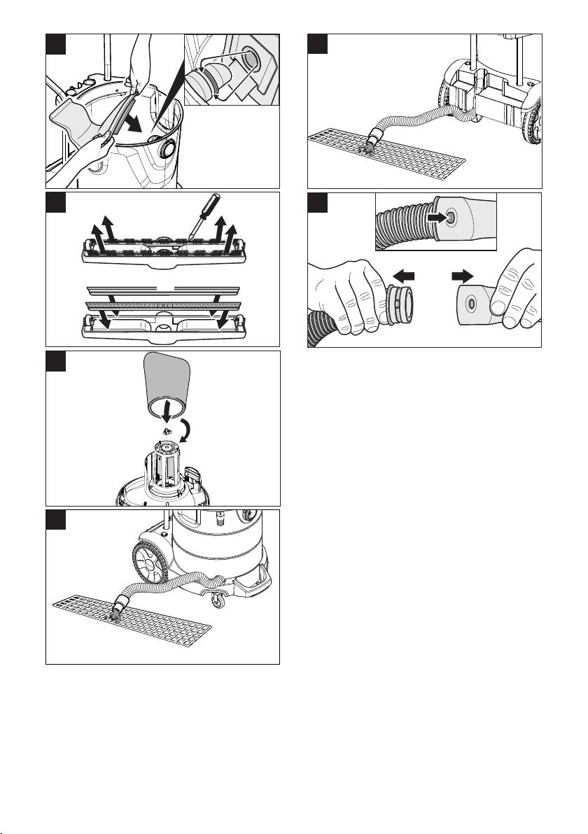
Schmutzwasser ablassen
Gerät aufbewahren
Vorsicht
Saugschlauch und Netzkabel aufwi-
Örtliche Vorschriften zur Abwasserbehand-
ckeln und über den Schubbügel hän-
lung beachten.
gen.
Gerät mit Metallbehälter:
Gerät in einem trockenen Raum abstel-
Abbildung
len und vor unbefugter Benutzung si-
Gerät mit Kunststoffbehälter:
chern.
Abbildung
Schmutzwasser über Ablassschlauch
Transport
ablassen.
Vorsicht
Clipverbindung
Verletzungs- und Beschädigungsgefahr!
Abbildung
Gewicht des Gerätes beim Transport be-
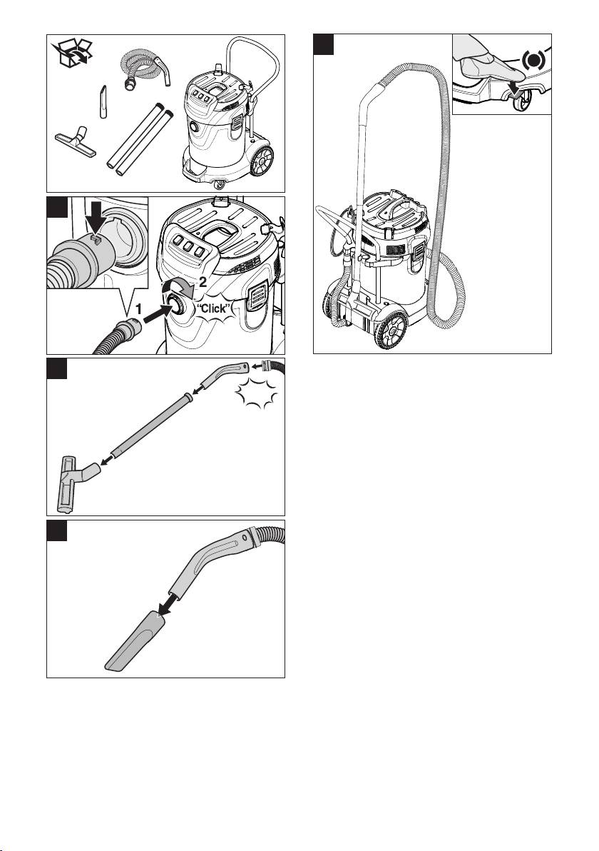
Der Saugschlauch ist mit einem Clip-Sys-
achten.
tem ausgestattet. Alle C-40/C-DN-40 Zube-
Saugrohr mit Bodendüse aus der Halte-
hörteile können angeschlossen werden.
rung nehmen. Gerät zum Tragen am
Tragegriff und am Saugrohr fassen,
Bedienung
nicht am Schubbügel.
Zum Transport über längere Strecken
Gerät einschalten
Gerät am Schubbügel hinter sich her-
Netzstecker einstecken.
ziehen.
Gerät einschalten.
Beim Transport in Fahrzeugen Gerät
nach den jeweils gültigen Richtlinien
gegen Rutschen und Kippen sichern.
– 3
7DE

Lagerung
Saugturbine läuft nach Behälterent-
leerung nicht wieder an
Vorsicht
Gerät ausschalten und 5 Sekunden
Verletzungs- und Beschädigungsgefahr!
warten, nach 5 Sekunden wieder ein-
Gewicht des Gerätes bei Lagerung beach-
schalten.
ten.
Dieses Gerät darf nur in Innenräumen gela-
Saugkraft lässt nach
gert werden.
Verstopfungen aus Saugdüse, Saug-
Pflege und Wartung
rohr, Saugschlauch oder Patronenfilter
entfernen.
Gefahr
Dichtring zwischen Saugkopf und Be-
Vor allen Arbeiten am Gerät, Gerät aus-
hälter erneuern.
schalten und Netzstecker ziehen.
Papierfiltertüte wechseln.
Patronenfilter wechseln
Membranfilter (Sonderzubehör) unter
fließendem Wasser reinigen bzw.
Saugkopf entriegeln und abnehmen.
wechseln.
Sternschraube abschrauben, Patro-
Patronenfilter wechseln.
nenfilter abziehen und durch einen neu-
Ablassschlauch auf Dichtheit überprü-
en ersetzen.
fen.
Sternschraube festschrauben.
Saugkopf aufsetzen und verriegeln.
Staubaustritt beim Saugen
Mechanischen Überlaufschutz rei-
Korrekte Einbaulage des Patronenfil-
nigen
ters überprüfen.
Patronenfilter wechseln.
Saugkopf entriegeln und abnehmen.
Sternschraube abschrauben und Patro-
Mechanischer Überlaufschutz
nenfilter abziehen.
(Nasssaugen) funktioniert nicht
Mechanischen Überlaufschutz mit ei-
Schwimmer auf Leichtgängigkeit kont-
nem feuchten Tuch reinigen.
rollieren, bei Bedarf mit einem feuchten
Patronenfilter aufstecken.
Tuch reinigen oder austauschen.
Sternschraube festschrauben.
Garantie
Saugkopf aufsetzen und verriegeln.
In jedem Land gelten die von unserer zu-
Hilfe bei Störungen
ständigen Vertriebsgesellschaft herausge-
Gefahr
gebenen Garantiebedingungen. Etwaige
Vor allen Arbeiten am Gerät, Gerät aus-
Störungen an Ihrem Gerät beseitigen wir
schalten und Netzstecker ziehen.
innerhalb der Garantiefrist kostenlos, so-
fern ein Material- oder Herstellungsfehler
Saugturbine läuft nicht
die Ursache sein sollte. Im Garantiefall
Steckdose und Sicherung der Strom-
wenden Sie sich bitte mit Kaufbeleg an Ih-
versorgung überprüfen.
ren Händler oder die nächste autorisierte
Netzkabel, Netzstecker und mechani-
Kundendienststelle.
schen Überlaufschutz überprüfen.
Gerät einschalten.
Saugturbine schaltet ab
Behälter entleeren.
8 DE
– 4

Zubehör und Ersatzteile EG-Konformitätserklärung
– Es dürfen nur Zubehör und Ersatzteile
Hiermit erklären wir, dass die nachfolgend
verwendet werden, die vom Hersteller
bezeichnete Maschine aufgrund ihrer Kon-
freigegeben sind. Original-Zubehör und
zipierung und Bauart sowie in der von uns
Original-Ersatzteile bieten die Gewähr
in Verkehr gebrachten Ausführung den ein-
dafür, dass das Gerät sicher und stö-
schlägigen grundlegenden Sicherheits-
rungsfrei betrieben werden kann.
und Gesundheitsanforderungen der EG-
– Eine Auswahl der am häufigsten benö-
Richtlinien entspricht. Bei einer nicht mit
tigten Ersatzteile finden Sie am Ende
uns abgestimmten Änderung der Maschine
der Betriebsanleitung.
verliert diese Erklärung ihre Gültigkeit.
– Weitere Informationen über Ersatzteile
Produkt: Nass- und Trockensauger
erhalten Sie unter www.kaercher.com
Typ: 1.667-xxx
im Bereich Service.
Einschlägige EG-Richtlinien
2006/42/EG (+2009/127/EG)
2004/108/EG
Angewandte harmonisierte Normen
EN 55014–1: 2006+A1: 2009+A2: 2011
EN 55014–2: 1997+A1: 2001+A2: 2008
EN 60335–1
EN 60335–2–69
EN 61000–3–2: 2006+A1: 2009+A2: 2009
EN 61000–3–3: 2008
EN 62233: 2008
Angewandte nationale Normen
-
5.957-702
Die Unterzeichnenden handeln im Auftrag
und mit Vollmacht der Geschäftsführung.
CEO
Head of Approbation
Dokumentationsbevollmächtigter:
S. Reiser
Alfred Kärcher GmbH & Co. KG
Alfred-Kärcher-Str. 28 - 40
71364 Winnenden (Germany)
Tel.: +49 7195 14-0
Fax: +49 7195 14-2212
Winnenden, 2010/09/01
– 5
9DE

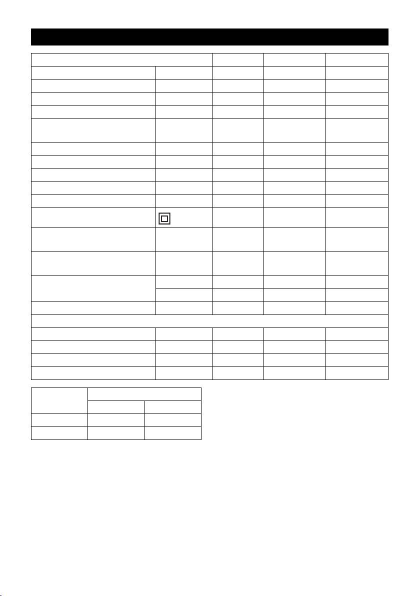
Technische Daten
NT 70/1 NT 70/2 NT 70/3
Netzspannung V 220-240 220-240 220-240
Frequenz Hz 1~ 50/60 1~ 50/60 1~ 50/60
Max. Leistung W 1200 2400 3600
Nennleistung W 1050 2100 3150
Maximal zulässige Netzimpe-
Ohm -- (0.282+j0.176) (0.195+j0.122)
danz
Behälterinhalt l 71 71 71
Füllmenge Flüssigkeit l 57 57 57
Luftmenge (max.) l/s 56 2x 56 3x 56
Unterdruck (max.) kPa (mbar) 20,8 (208) 20,8 (208) 20,8 (208)
Schutzart -- IPX4 IPX4 IPX4
Schutzklasse II II II
Saugschlauchanschluss
mm 40 40 40
(C-DN/C-ID)
Länge x Breite x Höhe mm 720 x 510 x
720 x 510 x
720 x 510 x
975
975
975
Typisches Betriebsgewicht kg 22,9 25,2 27,6
kg -- 25,6 (Me) --
Umgebungstemperatur (max.) °C +40 +40 +40
Ermittelte Werte gemäß EN 60335-2-69
Schalldruckpegel L
pA
dB(A) 73 75 79
Unsicherheit K
pA
dB(A) 1 1 1
2
Hand-Arm Vibrationswert m/s
<2,5 <2,5 <2,5
2
Unsicherheit K m/s
0,2 0,2 0,2
2
Netzkabel H05VV-F 2x1,5 mm
Teile-Nr. Kabellänge
EU 6.647-069.0 10 m
GB 6.649-803.0 10 m
10 DE
– 6
Please read and comply with
Environmental protection
these original instructions prior
to the initial operation of your appliance and
The packaging material can be
store them for later use or subsequent own-
recycled. Please do not throw
ers.
the packaging material into
– Before first start-up it is definitely nec-
household waste; please send it
essary to read the safety indications Nr.
for recycling.
5.956-249!
Old appliances contain valuable
– The non-compliance of the operating
materials that can be recycled;
and safety instructions may lead to
these should be sent for recy-
damages of the appliance and to dan-
cling. Batteries, oil, and similar
gers for the operator and other persons.
substances must not enter the
– In case of transport damage inform ven-
environment. Please dispose of
dor immediately
your old appliances using ap-
Contents
propriate collection systems.
Notes about the ingredients (REACH)
Environmental protection . . EN . . .1
You will find current information about the
Symbols in the operating in-
ingredients at:
structions . . . . . . . . . . . . . . EN . . .1
www.kaercher.com/REACH
Proper use . . . . . . . . . . . . . EN . . .1
Device elements. . . . . . . . . EN . . .2
Symbols in the operating
Start up. . . . . . . . . . . . . . . . EN . . .2
instructions
Operation . . . . . . . . . . . . . . EN . . .3
Danger
Transport . . . . . . . . . . . . . . EN . . .3
Immediate danger that can cause severe
Storage. . . . . . . . . . . . . . . . EN . . .3
injury or even death.
Maintenance and care . . . . EN . . .3
몇 Warning
Troubleshooting . . . . . . . . . EN . . .4
Possible hazardous situation that could
Warranty. . . . . . . . . . . . . . . EN . . .4
lead to severe injury or even death.
Accessories and Spare Parts EN . . .4
Caution
EC Declaration of Conformity EN . . .5
Possible hazardous situation that could
Technical specifications . . . EN . . .6
lead to mild injury to persons or damage to
property.
Proper use
몇 Warning
The appliance is not suitable for vacuuming
dust which endangers health.
– The machine is meant for dry and wet
cleaning of floors and walls.
– This appliance is suited for the commer-
cial use, e.g. in workshops, industrial
companies, schools and hotels.
– Room temperature should not exceed
40 °C.
– The appliance should never weigh
more than 100 kg with additional loads.
– 1
11EN

Device elements
Dry vacuum cleaning
1 Star screw
Caution
2 Cartridge filter
The cartridge filter must never be removed
3 Mechanical overflow protection
during vacuuming.
– When vacuuming fine dust, you may
4 Suction head
also use an additional paper filter bag or
5 Suction hose
a membrane filter (special accessory).
6 Push handle
7 Cable hook
Inserting the paper filter bag (option)
8 Wheel
Illustration
Release and remove the suction head.
9 Suction head lock
Insert the paper filter bag or the mem-
10 Dirt receptacle
brane filter (special attachment).
11 Suction support
Insert and lock the suction head.
12 Steering roller
13 Chassis
Wet vacuum cleaning
14 Chassis handle
Inserting the rubber lips
15 Floor nozzle
Illustration
16 Suction tube
Remove the brush strips.
17 Carrying handle
Install the rubber lips.
18 Bender
Note: The structured side of the rubber lips
19 Appliance switch suction turbine 2
must point outwards.
20 Appliance switch suction turbine 1
Remove the paper filter bag
21 Appliance switch suction turbine 3
– If the appliance is used to vacuum wet
22 Storage for floor nozzle
dirt the paper filter bag or the mem-
23 Drain hose
brane filter (special accessory) must al-
24 Holder for suction pipes
ways be removed.
25 Holder for crevice nozzle
– It is recommended to use a special filter
26 Power cord
bag (wet) (see Filter systems).
27 Nameplate
Wet vacuuming with cartridge filter
Start up
Caution
The cartridge filter must never be removed
Caution
during vacuuming.
The highest allowed net impedance at the
– After the wet vacuuming: Clean the me-
electrical connection point (refer to techni-
chanical overflow protection and the
cal data) is not to be exceeded. In case of
container with a damp rag and dry
confusion regarding the power impedance
them.
present on your connection, please contact
– If you change immediately from wet to
your utilities provider.
dry vacuuming, then replace the wet
cartridge filter with a dry one.
Wet vacuuming with wet filter (optional)
Release and remove the suction head.
Unscrew the star scew and pull out the
cartridge filter.
12 EN
– 2

Illustration
Turn off the appliance
Tighten the star screw.
Turn off the appliance.
Install the wet filter.
Pull out the mains plug.
Insert and lock the suction head.
Caution
After each operation
The wet filter must never be removed dur-
Empty the container.
ing the vacuuming.
Vacuum and wipe the appliance inside
– After the wet vacuuming: Clean the me-
and outside with a damp cloth.
chanical overflow protection and the
container with a damp rag and dry
Storing the Appliance
them.
Wind the suction hose and the mains ca-
– If you change immediately from wet to
ble and hang it over the pushing handle.
dry vacuuming, replace the wet filter
Place the appliance in a dry room and
with a cartridge filter.
secure it from unauthorized use.
Drain off dirt water
Transport
Caution
Please observe the local provisions regard-
Caution
ing the wastewater treatment.
Risk of injury and damage! Observe the
Appliance with metal container:
weight of the appliance when you transport
Illustration
it.
Appliance with plastic container:
Remove the suction pipe with the floor
Illustration
nozzle from the holder. Hold the appli-
Drain off dirty water through the drain-
ance by the handle and at the suction
age hose.
pipe to transport it, not by the push han-
dle.
Clip connection
Pull the device behind you at the carry-
Illustration
ing handle for transporting it over longer
The suction hose is equipped with a clip
distances
system. All C-40/C-DN-40 accessories can
When transporting in vehicles, secure
be connected.
the appliance according to the guide-
Operation
lines from slipping and tipping over.
Storage
Turning on the Appliance
Caution
Plug in the main plug.
Turn on the appliance.
Risk of injury and damage! Note the weight
of the appliance in case of storage.
Emptying the dirt container
This appliance must only be stored in inte-
– The vacuum channel is equipped with a
rior rooms.
float.
Maintenance and care
– When the dirt water reaches the highest
permissible level in the container, the
Danger
suction power is interrupted.
First pull out the plug from the mains before
Turn off the appliance.
carrying out any tasks on the machine.
Empty the container.
– 3
13EN

Change cartridge filter
Suction capacity decreases
Release and remove the suction head.
Remove choking of suction nozzle, suc-
Unscrew the star screw, pull out the
tion tube, suction hose, or cartridge filter.
cartridge filter and replace with a new
Replace the washer between the suc-
one.
tion head and the container.
Tighten the star screw.
Exchange the paper filter bag.
Insert and lock the suction head.
Clean or replace the membrane filter
(special accessory) under running water.
Cleaning the mechanical overflow
Change cartridge filter.
safeguard
Check drain pipe for leaks.
Release and remove the suction head.
Dust comes out while vacuuming
Unscrew the star scew and pull out the
cartridge filter.
Check the proper installation of the car-
Clean the mechanical overflow protec-
tridge filter.
tion with a moist cloth.
Change cartridge filter.
Replace the cartridge filters.
Mechanical overflow safeguard (wet
Tighten the star screw.
suction) does not function
Insert and lock the suction head.
Check swimmer for easy accessibility;
Troubleshooting
clean with a moist rag or replace as
need be.
Danger
First pull out the plug from the mains before
Warranty
carrying out any tasks on the machine.
The warranty terms published by the rele-
Suction turbine does not run
vant sales company are applicable in each
country. We will repair potential failures of
Check the receptacle and the fuse of
your appliance within the warranty period
the power supply.
free of charge, provided that such failure is
Check power cable, mains plug and
caused by faulty material or defects in man-
mechanical overflow protection.
ufacturing. In the event of a warranty claim
Turn on the appliance.
please contact your dealer or the nearest
Suction turbine turns off
authorized Customer Service centre.
Please submit the proof of purchase.
Empty the container.
Accessories and Spare Parts
Suction turbine does not start again
after the container has been
– Only use accessories and spare parts
emptied
which have been approved by the man-
ufacturer. The exclusive use of original
Turn off the appliance and wait for 5
accessories and original spare parts
seconds, turn it on again after 5 sec-
ensures that the appliance can be oper-
onds.
ated safely and trouble free.
– At the end of the operating instructions
you will find a selected list of spare parts
that are often required.
– For additional information about spare
parts, please go to the Service section
at www.kaercher.com.
14 EN
– 4

EC Declaration of Conformity
We hereby declare that the machine de-
scribed below complies with the relevant
basic safety and health requirements of the
EU Directives, both in its basic design and
construction as well as in the version put
into circulation by us. This declaration shall
cease to be valid if the machine is modified
without our prior approval.
Product: Wet and dry vacuum cleaner
Type: 1.667-xxx
Relevant EU Directives
2006/42/EC (+2009/127/EC)
2004/108/EC
Applied harmonized standards
EN 55014–1: 2006+A1: 2009+A2: 2011
EN 55014–2: 1997+A1: 2001+A2: 2008
EN 60335–1
EN 60335–2–69
EN 61000–3–2: 2006+A1: 2009+A2: 2009
EN 61000–3–3: 2008
EN 62233: 2008
Applied national standards
-
5.957-702
The undersigned act on behalf and under
the power of attorney of the company man-
agement.
CEO
Head of Approbation
Authorised Documentation Representative
S. Reiser
Alfred Kärcher GmbH Co. KG
Alfred-Kärcher-Str. 28 - 40
71364 Winnenden (Germany)
Phone: +49 7195 14-0
Fax: +49 7195 14-2212
Winnenden, 2010/09/01
– 5
15EN
Technical specifications
NT 70/1 NT 70/2 NT 70/3
Mains voltage V 220-240 220-240 220-240
Frequency Hz 1~ 50/60 1~ 50/60 1~ 50/60
Max. performance W 1200 2400 3600
Rated power W 1050 2100 3150
Maximum allowed net imped-
Ohm -- (0.282+j0.176) (0.195+j0.122)
ance
Container capacity l 71 71 71
Filling quantity (liquid) l 57 57 57
Air volume (max.) l/s 56 2x 56 3x 56
Negative pressure (max.) kPa (mbar) 20,8 (208) 20,8 (208) 20,8 (208)
Type of protection -- IPX4 IPX4 IPX4
Protective class II II II
Suction hose connection
mm 40 40 40
(C-DN/C-ID)
Length x width x height mm 720 x 510 x
720 x 510 x
720 x 510 x
975
975
975
Typical operating weight kg 22,9 25,2 27,6
kg -- 25.6 (Me) --
Max. ambient temperature °C +40 +40 +40
Values determined to EN 60335-2-69
Sound pressure level L
pA
dB(A) 73 75 79
Uncertainty K
pA
dB(A) 1 1 1
2
Hand-arm vibration value m/s
<2,5 <2,5 <2,5
2
Uncertainty K m/s
0,2 0,2 0,2
2
Power cord H05VV-F 2x1,5 mm
Part no.: Cable length
EU 6.647-069.0 10 m
GB 6.649-803.0 10 m
16 EN
– 6
Lire ces notice originale avant la
Les appareils usés contiennent
première utilisation de votre ap-
des matériaux précieux recy-
pareil, se comporter selon ce qu'elles re-
clables lesquels doivent être ap-
quièrent et les conserver pour une
portés à un système de
utilisation ultérieure ou pour le propriétaire
recyclage. Il est interdit de jeter
les batteries, l'huile et les subs-
futur.
tances similaires dans l'environ-
– Avant la première mise en service, vous
nement. Pour cette raison,
devez impérativement avoir lu les
utiliser des systèmes de collecte
consignes de sécurité N° 5.956-249 !
adéquats afin d'éliminer les ap-
– En cas de non-respect des instructions
pareils hors d'usage.
de service et des consignes de sécuri-
Instructions relatives aux ingrédients
té, l'appareil risque de subir des dom-
(REACH)
mages matériel et l'utilisateur ainsi que
Les informations actuelles relatives aux in-
toute tierce personne sont exposés à
grédients se trouvent sous :
des dangers potentiels.
www.kaercher.com/REACH
– Contactez immédiatement le revendeur
en cas d'avarie de transport.
Symboles utilisés dans le
mode d'emploi
Table des matières
Danger
Protection de l’environnement FR . . .1
Pour un danger immédiat qui peut avoir
Symboles utilisés dans le mode
pour conséquence la mort ou des bles-
d'emploi . . . . . . . . . . . . . . . FR . . .1
sures corporelles graves.
Utilisation conforme . . . . . . FR . . .1
Éléments de l'appareil . . . . FR . . .2
몇 Avertissement
Mise en service . . . . . . . . . FR . . .2
Pour une situation potentiellement dange-
reuse qui peut avoir pour conséquence des
Utilisation . . . . . . . . . . . . . . FR . . .3
blessures corporelles graves ou la mort.
Transport . . . . . . . . . . . . . . FR . . .3
Entreposage. . . . . . . . . . . . FR . . .4
Attention
Entretien et maintenance . . FR . . .4
Pour une situation potentiellement dangereuse
qui peut avoir pour conséquence des blessures
Assistance en cas de panne FR . . .4
légères ou des dommages matériels.
Garantie . . . . . . . . . . . . . . . FR . . .5
Accessoires et pièces de re-
Utilisation conforme
change . . . . . . . . . . . . . . . . FR . . .5
Déclaration de conformité CE FR . . .5
몇 Avertissement
Caractéristiques techniques FR . . .6
Cet appareil n'est pas conçu pour aspirer
des poussières nocives.
Protection de
– Cet aspirateur est destiné au nettoyage
l’environnement
à sec et au nettoyage par voie humide
des sol et murs.
Les matériaux constitutifs de
– Cet appareil convient à un usage pro-
l’emballage sont recyclables.
fessionnel et industriel, par exemple
Ne pas jeter les emballages
dans le cadre d'ateliers, d'exploitations
dans les ordures ménagères,
industrielles, d'écoles et d'hôtels.
mais les remettre à un système
– La température de la pièce ne doit pas
de recyclage.
dépasser 40° C.
– Le poids maximal autorisé de l'appareil
charge incluse est de 100 kg.
– 1
17FR

Éléments de l'appareil
Aspiration de poussières
1 Vie en étoile
Attention
2 Filtre-cartouche
Le filtre à cartouches ne doit jamais être re-
3 Protection anti-débordement méca-
tiré durant l'aspiration.
nique
– Pour l'aspiration de poussières fines, il
est possible d'utiliser de surcroît un sac
4 Tête d'aspiration
de filtrage en papier ou un filtre à mem-
5 Flexible d’aspiration
branes (accessoire spécial).
6 Guidon de poussée
7 Crochet de câble
Montage sac filtrant en papier (option)
8 Roue
Illustration
Déverrouiller et retirer la tête d'aspiration.
9 Verrouillage de la tête d'aspiration
Mettre en place le sac de filtrage en pa-
10 Récipient collecteur
pier ou le filtre à membranes (acces-
11 Consoles d'aspiration
soire spécial).
12 Galet de direction
Positionner la tête d'aspiration et la ver-
13 Bâti de transport
rouiller.
14 Poignée du châssis
15 Buse pour sol
Aspiration humide
16 Tuyau d'aspiration
Montage des lèvres en caoutchouc
17 Poignée de transport
Illustration
18 Coude
Démonter les bandes de brosse
19 Interrupteur d'appareil turbine d'aspira-
Monter les lèvres en caoutchouc.
tion 2
Remarque : la face structurée des lèvres en
20 Interrupteur d'appareil turbine d'aspira-
caoutchouc doit être dirigée vers l'extérieur.
tion 1
Retirer le sachet filtre en papier.
21 Interrupteur d'appareil turbine d'aspira-
– Pour aspirer des saletés humides, il
tion 3
faut toujours retirer le sachet filtre en
22 Rangement pour la buse de sol.
papier ou bien le filtre à membrane (ac-
23 Flexible d'écoulement
cessoires spéciaux).
24 Support pour tubes d'aspiration
– Il est recommandé d'utiliser un filtre pa-
25 Support pour buse à joint
pier spécial (humide) (voir systèmes de
26 Câble d’alimentation
filtration).
27 Plaque signalétique
Aspiration humide avec cartouche fil-
Mise en service
trante
Attention
Attention
Le filtre à cartouches ne doit jamais être re-
L'impédance de réseau maximale admis-
tiré durant l'aspiration.
sible au niveau du point de raccordement
– À la fin de l'aspiration humide : Nettoyer
ne doit en aucun cas être dépassée (voir
la protection mécanique contre le trop-
Caractéristiques techniques). En cas de
plein ainsi que le réservoir avec un chif-
doute concernant l'impédance de réseau
fon humide et les sécher.
présente sur votre point de raccordement,
– En cas de passage sans délai de l'aspi-
veuillez vous adresser à l'entreprise res-
ration de liquide à l'aspiration sèche, le
ponsable de votre alimentation énergé-
filtre à cartouche mouillée doit être rem-
tique.
placé par un filtre à cartouche sèche.
18 FR
– 2

Aspiration humide avec filtre humide
Vider le récipient collecteur
(option)
– Le canal d'aspiration est équipé d'un
Déverrouiller et retirer la tête d'aspira-
flotteur.
tion.
– Lorsque le niveau maximal admissible
Dévisser la vis en étoile et retirer le filtre
d'eau sale est atteint dans le réservoir,
à cartouche.
le débit d'aspiration est stoppé.
Illustration
Mettre l’appareil hors tension.
Serrer la vis en étoile.
Vider le réservoir.
Mettre le filtre humide en place.
Positionner la tête d'aspiration et la ver-
Mise hors service de l'appareil
rouiller.
Mettre l’appareil hors tension.
Attention
Retirer le connecteur de la prise.
Le filtre humide ne doit jamais être retiré
Après chaque mise en service
durant l'aspiration.
– À la fin de l'aspiration humide : Nettoyer
Vider le réservoir.
la protection mécanique contre le trop-
Nettoyer la partie intérieure et exté-
plein ainsi que le réservoir avec un chif-
rieure de l'appareil en l'aspirant et en
fon humide et les sécher.
l'essuyant avec un chiffon humide.
– En cas de passage de l'aspiration hu-
Ranger l’appareil
mide à l'aspiration sèche, le filtre hu-
mide doit être remplacé par une
Enrouler le flexible d'aspiration et le
cartouche filtrante.
câble d'alimentation et l'accrocher sur
Vider l'eau sale
le guidon de poussée.
Entreposer l’appareil dans un endroit
Attention
sec et le sécuriser contre toute utilisa-
Tenir compte des prescriptions locales
tion non autorisée.
pour le traitement des eaux usées.
Appareil avec réservoir métallique :
Transport
Illustration
Appareil avec réservoir en plastique :
Attention
Illustration
Risque de blessure et d'endommagement !
Laisser l'eau sale s'écouler par le
Respecter le poids de l'appareil lors du
flexible de vidange.
transport.
Retirer le tube d'aspiration avec la buse
Clip de fixation
de sol du support. Pour transporter l'ap-
Illustration
pareil, le saisir au niveau de la poignée
Le flexible d'aspiration est doté d'un sys-
et du tube d'aspiration et non au niveau
tème à clip. Il est possible de raccorder
du guidon de poussée.
tous les accessoires C-40/C-DN-40.
Pour transporter l’appareil sur de plus
longues distances, le tirer derrière soi
Utilisation
au moyen du guidon de poussée.
Sécuriser l'appareil contre les glisse-
Mettre l'appareil en marche
ments ou les basculements selon les di-
Brancher la fiche secteur.
rectives en vigueur lors du transport
Allumer l’appareil.
dans des véhicules.
– 3
19FR

Entreposage
La turbine d'aspiration ne
fonctionne pas
Attention
Vérifier la prise et le fusible de l'alimen-
Risque de blessure et d'endommagement !
tation électrique.
Prendre en compte le poids de l'appareil à
Vérifier le câble d'alimentation, la fiche
l'entreposage.
secteur et le trop-plein mécanique.
Cet appareil doit uniquement être entrepo-
Allumer l’appareil.
sé en intérieur.
Turbine d'aspiration se met hors
Entretien et maintenance
marche
Danger
Vider le réservoir.
Avant d'effectuer tout type de travaux sur
l'appareil, le mettre hors service et débran-
Turbine d'aspiration ne se remet
cher la fiche électrique.
pas en marche après avoir vidé la
cuve
Remplacement de la cartouche
filtrante
Mettre l'appareil hors marche et at-
tendre 5 secondes avant de le remettre
Déverrouiller et retirer la tête d'aspira-
en marche.
tion.
Dévisser la vis en étoile, retirer le filtre à
La force d'aspiration diminue
cartouche et le remplacer par un neuf.
Déboucher la buse d'aspiration, le
Serrer la vis en étoile.
tuyau d'aspiration, le flexible d'aspira-
Positionner la tête d'aspiration et la ver-
tion ou la cartouche filtrante.
rouiller.
Remplacer la bague d'étanchéité entre
Nettoyer la sécurité
la tête d'aspiration et la cuve.
anti-débordement mécanique
Remplacer le sachet filtre en papier.
Nettoyer le filtre à membrane (acces-
Déverrouiller et retirer la tête d'aspira-
soire spécial) à l'eau courante ou le
tion.
remplacer.
Dévisser la vis en étoile et retirer le filtre
Remplacer la cartouche filtrante.
à cartouche.
Contrôler l'étanchéité du flexible de vi-
Nettoyer la protection mécanique de
dange.
trop-plein à l'aide d'un chiffon humide.
Enficher le filtre à cartouche.
De la poussière s'échappe lors de
Serrer la vis en étoile.
l'aspiration
Positionner la tête d'aspiration et la ver-
Vérifier le positionnement de la car-
rouiller.
touche filtrante.
Assistance en cas de panne
Remplacer la cartouche filtrante.
La protection anti-dépassement
Danger
mécanique (aspiration de liquide)
Avant d'effectuer tout type de travaux sur
ne fonctionne pas
l'appareil, le mettre hors service et débran-
cher la fiche électrique.
Contrôler la mobilité du flotteur, si né-
cessaire le nettoyer à l'aide d'un chiffon
humide ou le remplacer.
20 FR
– 4
