Karcher IP 220: инструкция
Раздел: Прочее
Тип: Прочее
Характеристики, спецификации
Инструкция к Прочее Karcher IP 220
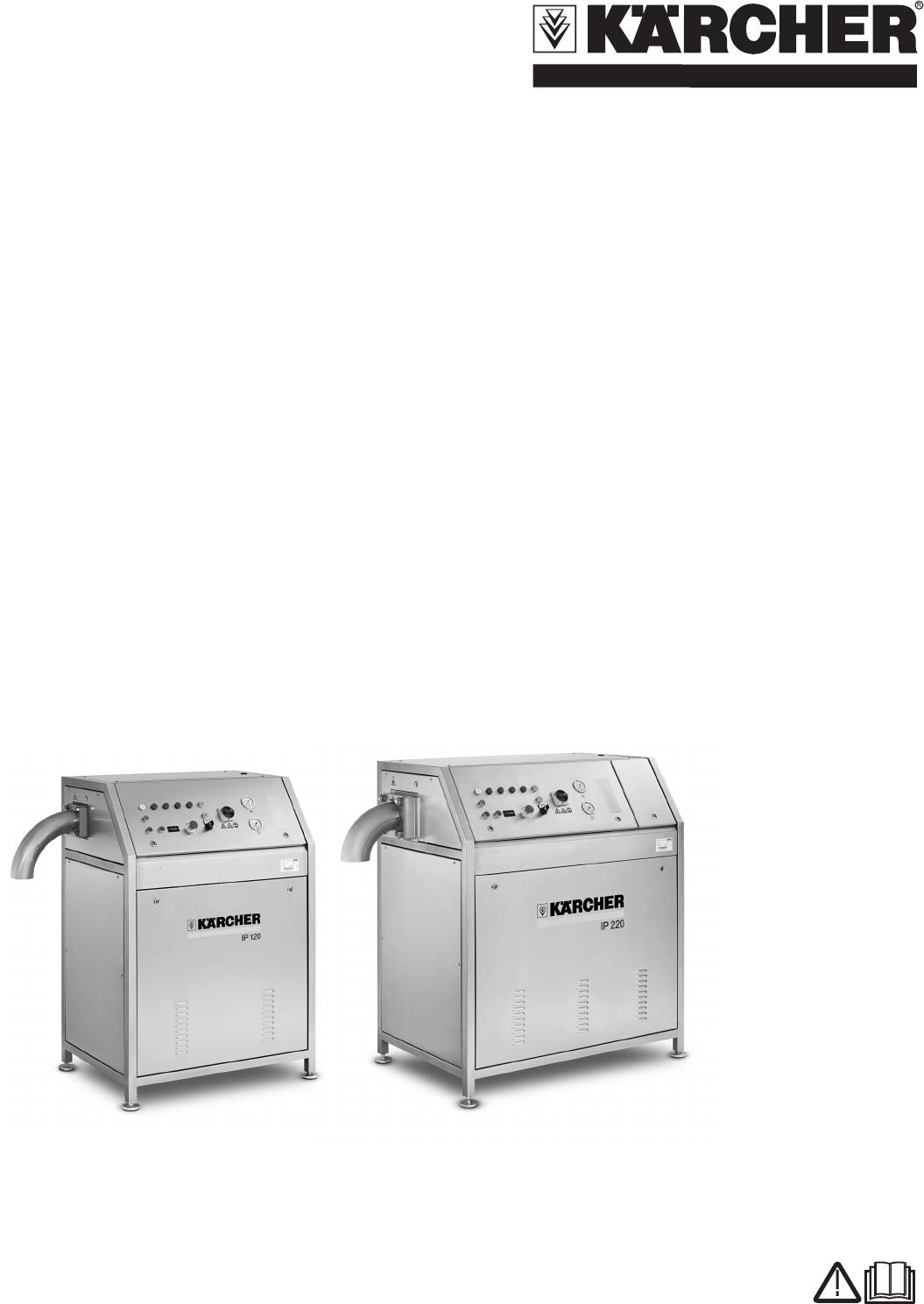
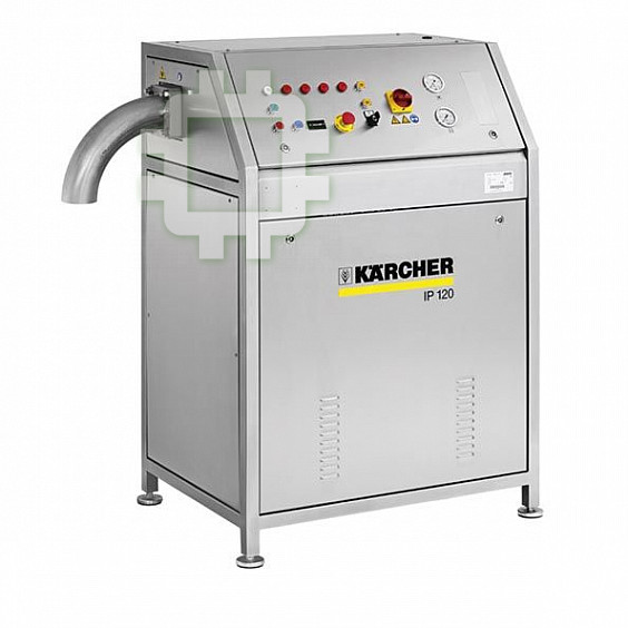
IP 120
IP 220
Deutsch 3
English 11
Français 19
Italiano 27
Español 35
Português 43
Nederlands 51
Ελληνικά 59
Türkçe 67
Svenska 75
Suomi 83
Norsk 91
Dansk 99
Eesti 107
Latviešu 115
Lietuviškai 123
Руccкий 131
Українська 141
Polski 149
5.962-286.0 03/08
Lesen Sie vor der ersten Be-
Hinweis
Allgemeine Sicherheitshinweise
nutzung Ihres Gerätes diese
Bezeichnet Anwendungstipps und wichtige
Gefahr
Betriebsanleitung und handeln Sie danach.
Informationen.
Bewahren Sie diese Betriebsanleitung für
Erstickungsgefahr durch Kohlendioxid. Die
Symbole auf dem Gerät
späteren Gebrauch oder für Nachbesitzer
Trockeneispellets bestehen aus festem Koh-
auf.
lendioxid. Beim Betrieb des Gerätes steigt
der Kohlendioxidgehalt der Luft am Arbeits-
Inhaltsverzeichnis
platz. Arbeitsplatz ausreichend lüften, ggf. ein
Umweltschutz 3
Personenwarngerät verwenden.
Anzeichen hoher Kohlendioxidkonzentration
Sicherheitshinweise 3
Gefahr
in der Atemluft:
Bestimmungsgemäße Verwendung 4
– 3...5%: Kopfschmerzen, hohe Atemfre-
Gefahr von Kälteverbrennungen. Trocken-
Funktion 4
quenz.
eis hat eine Temperatur von -79 °C. Tro-
Bedienelemente 4
ckeneis und kalte Geräteteile nie
– 7...10%: Kopfschmerzen, Brechreiz,
Anbausatz Waage montieren (Option) 5
ungeschützt berühren.
evtl. Bewusstlosigkeit.
Betrieb 5
Beim Auftreten dieser Anzeichen sofort
Gerät abstellen und an die frische Luft ge-
Außerbetriebnahme 6
hen, vor Fortsetzung der Arbeit Lüftungs-
Extruderplatte wechseln 6
maßnahmen verbessern .
Wartung und Pflege 7
Sicherheitsdatenblatt des Kohlendioxidher-
Hilfe bei Störungen 9
stellers beachten.
Gefahr
Technische Daten 10
Verbrennungsgefahr! Warnung vor heißen
Gefahr
Zubehör 10
Baugruppen.
Verletzungsgefahr durch unbeabsichtigt
Garantie 10
anlaufendes Gerät. Vor Arbeiten am Gerät
CE-Erklärung 10
Netzstecker aus der Steckdose ziehen.
Gefahr
Umweltschutz
Gefahr von Kälteverbrennungen durch Tro-
ckeneis oder kalte Geräteteile. Bei Arbeiten
Gefahr
Die Verpackungsmaterialien
am Gerät geeignete Kälteschutzkleidung
sind recyclebar. Bitte werfen
Verletzungsgefahr durch elektrischen
tragen oder Trockeneis entfernen und Ge-
Sie die Verpackungen nicht in
Schlag. Vor dem Öffnen des Steuer-
rät aufwärmen lassen.
den Hausmüll, sondern führen
schranks Netzstecker aus der Steckdose
Körperkontakt mit Trockeneis vermeiden.
Sie diese einer Wiederverwer-
ziehen.
Trockeneis nie in den Mund nehmen.
tung zu.
Erste Hilfe bei Unfällen mit Trocken-
Altgeräte enthalten wertvolle
eis oder flüssigem Kohlendioxid
recyclingfähige Materialien, die
Verschlucken
einer Verwertung zugeführt
Î Sofort medizinische Hilfe aufsuchen.
werden sollten. Batterien, Öl
Gefahr
und ähnliche Stoffe dürfen
Verletzungsgefahr durch austretenden Hy-
Augenkontakt
nicht in die Umwelt gelangen.
drauliköl-Strahl.
Î Auge mit viel warmem Wasser spülen
Bitte entsorgen Sie Altgeräte
Gerät nie mit offenem Gehäuse betreiben.
und sofort medizinische Hilfe aufsu-
deshalb über geeignete Sam-
Gerät bei Undichtigkeit im Hydrauliksystem
chen.
melsysteme.
sofort außer Betrieb nehmen.
Hautkontakt
Î Hautstellen mit viel warmem Wasser
Sicherheitshinweise
mindestens 15 Minuten lang berieseln
Das Gerät darf nur von Personen bedient
und sofort medizinische Hilfe aufsu-
werden, die diese Betriebsanleitung gele-
chen.
sen und verstanden haben. Insbesondere
Gefahr
Vorschriften und Richtlinien
müssen alle Sicherheitshinweise beachtet
werden.
Verletzungsgefahr durch herumfliegende
Für den Betrieb dieser Anlage gelten in der
Î Diese Betriebsanleitung so aufbewah-
Trockeneispellets oder Schmutzteilchen.
Bundesrepublik Deutschland folgende Vor-
ren, dass sie dem Bediener jederzeit
Dicht schließende Schutzbrille tragen.
schriften und Richtlinien (beziehbar über
zur Verfügung steht.
Gefahr von Gehörschäden. Gehörschutz
Carl Heymanns Verlag KG, Luxemburger
tragen.
Straße 449, 50939 Köln):
Symbole in der Betriebsanleitung
– BGR 189 Einsatz von Schutzkleidung
In dieser Betriebsanleitung werden folgen-
– BGR 195 Einsatz von Schutzhandschu-
de Symbole verwendet:
hen
Gefahr
– BGI 836 Gaswarner
Bezeichnet eine unmittelbar drohende Ge-
Ausschalten im Notfall
fahr. Bei Nichtbeachten des Hinweises dro-
Gefahr
hen Tod oder schwerste Verletzungen.
Î Not-Aus-Taster drücken.
Verletzungsgefahr durch herumfliegende
Das Gerät wird sofort stillgesetzt.
몇 Warnung
Trockeneispellets.
Bezeichnet eine möglicherweise gefährli-
Schutzhandschuhe nach EN 511 tragen.
che Situation. Bei Nichtbeachten des Hin-
weises können leichte Verletzungen oder
Sachschäden eintreten.
Deutsch 3
Gerät zur Reinigung nicht mit Wasser ab-
Bestimmungsgemäße Ver-
Funktion
spritzen. Gehäuse des Gerätes mit einem
wendung
feuchten Tuch reingen.
Flüssiges Kohlendioxid strömt in den Zylin-
Die Installation des Gerätes darf nur von
der und verfestigt sich durch den Druckab-
Das Gerät stellt Trockeneis-Pellets aus
autorisiertem Fachpersonal durchge-
fall zu Trockeneisschnee. Der
flüssigem Kohlendioxid her. Die Größe der
führt werden!
Trockeneisschnee wird von einen Hydrau-
Trockeneis-Pellets wird durch verschiede-
ne Extruderplatten gewählt.
몇 Warnung
likzylinder verdichtet und durch die Extru-
derplatte gepresst. Dadurch entstehen
Das Gerät ist zur Benutzung in trockenen
Die maximal zulässige Netzimpedanz am
zylindrische Trockeneisstäbchen, die zu
Räumen bestimmt.
elektrischen Anschlusspunkt (siehe Tech-
Pellets zerbrechen.
nische Daten) darf nicht überschritten wer-
den.
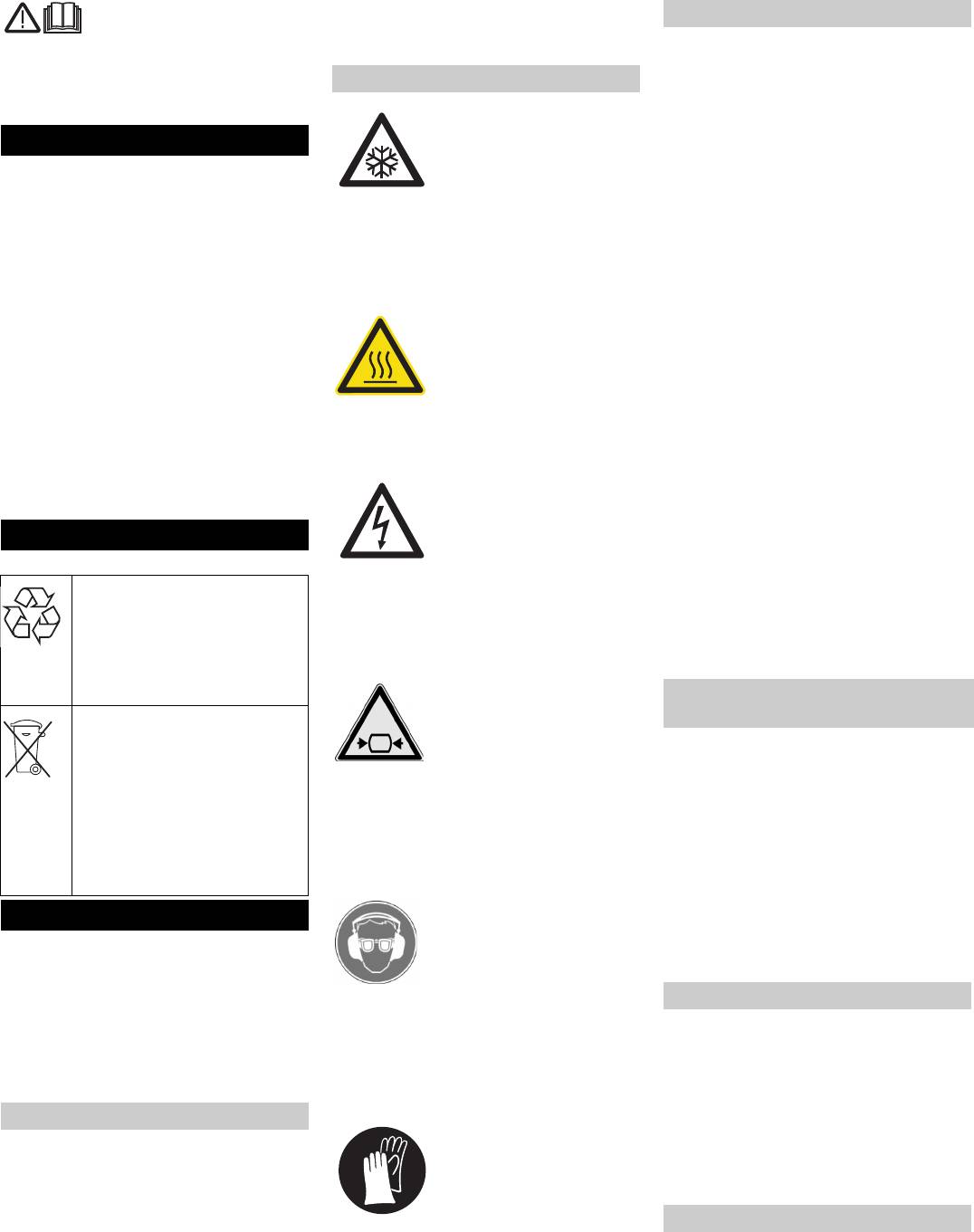
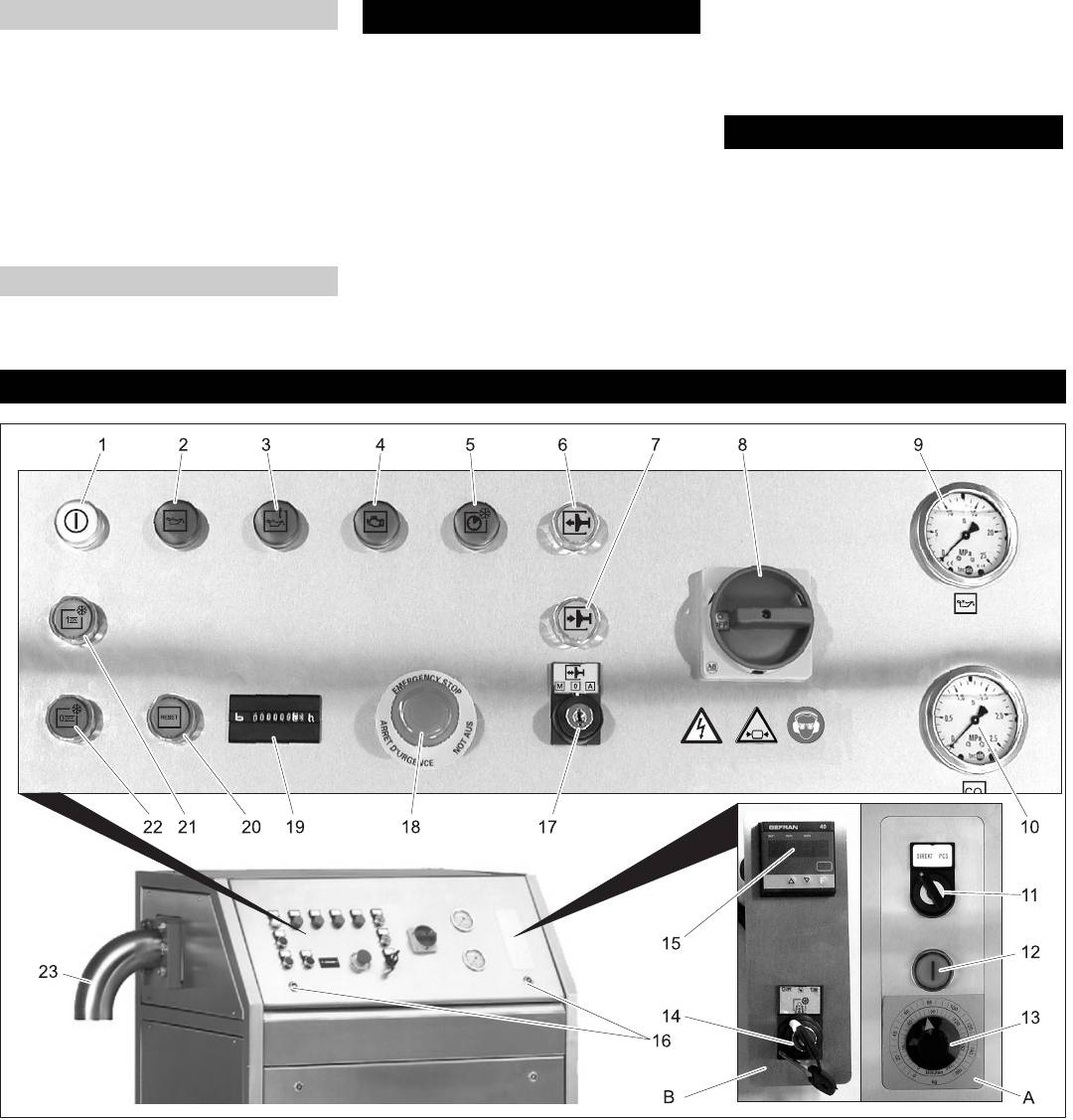
Bedienelemente
1 Kontrollleuchte „Spannung ein“
14 Schlüsselschalter „0/OFF / 1/ON“ (Opti-
2 Kontrollleuchte „Ölniveau tief“
on)
3 Kontrollleuchte „Öltemperatur hoch“
15 Gewichtsanzeige (Option)
4 Kontrollleuchte „Motor Überlast“
16 Verschluss Schaltschrank
5 Kontrollleuchte „Zyklus zu lang“
17 Schlüsselschalter „M/0/A“
Siehe „Hilfe bei Störungen/Störungen
M: Kolben kann für Wartungsarbeiten
mit Anzeige“.
manuell bewegt werden.
6 Taste „Kolben vor“
0: Gerät ist aus.
Der Kolben bewegt sich manuell ge-
A: Pelletproduktion.
steuert in die vorderste Position (Vor-
18 Not-Aus-Taster
aussetzung: Schlüsselschalter auf „M“)
19 Betriebsstundenzähler
7 Taste „Kolben zurück“
20 Taste „Reset“
Der Kolben bewegt sich manuell ge-
Setzt die automatische Betriebsunter-
steuert in die hinterste Position (Vor-
brechung nach einer Störung zurück.
aussetzung: Schlüsselschalter auf „M“)
21 Taste „Ein“
8 Hauptschalter
22 Taste „Aus“
9 Manometer Öldruck
Der Kolbenhub wird beendet, der Kol-
10 Manometer Kohlendioxid
ben bewegt sich in die vorderste Positi-
11 Schlüsselschalter „Direkt/PCS“ (Opti-
on, das Gerät stoppt.
on)
23 Pelletauswurf
12 Taste PCS starten (Option)
A Anbausatz Mengenregelung PCS (Op-
13 Drehknopf Produktionszeit/-menge
tion)
(Option)
B Anbausatz Waage (Option)
4 Deutsch
Î Not-Aus-Taster durch Drehen entrie-
Anbausätze montieren
geln.
몇
Warnung
Die Kontrollleuchte „Spannung ein“
leuchtet.
Anbausätze dürfen nur von autorisiertem
Fachpersonal montiert werden.
Anbausatz Waage montieren (Opti-
Î Leeren Behälter unter den Pelletaus-
on)
wurf stellen.
Î Ist der Anbausatz Waage installiert,
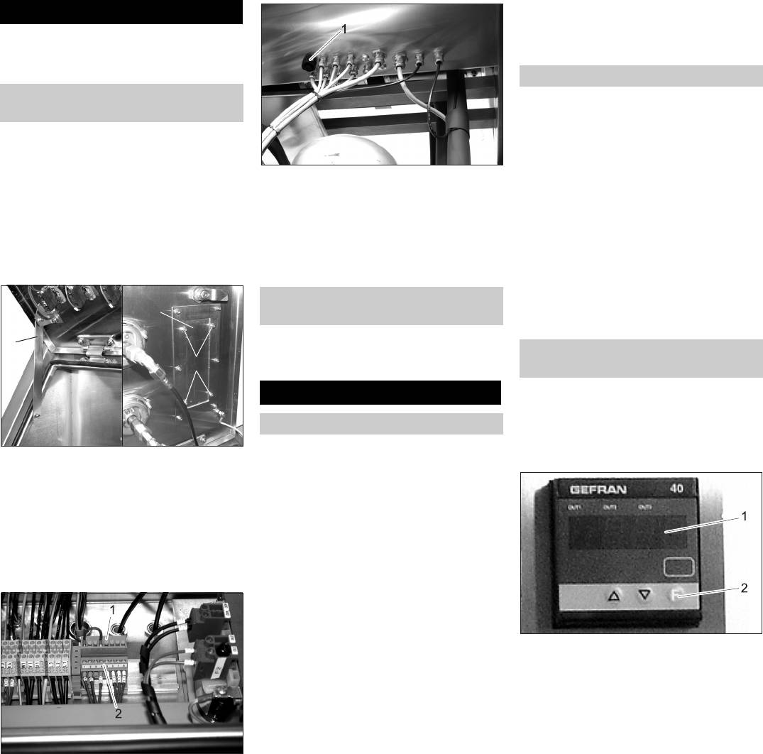
Steuerung einbauen
Schlüsselschalter „Ein/Aus“ auf „Aus“
Gefahr
stellen.
Verletzungsgefahr durch elektrischen
1 Stecker
Î Ist der Anbausatz Mengenregelung in-
Schlag. Vor dem Öffnen des Steuer-
stelliert, Schlüsselschalter „Direkt/PCS“
schranks Netzstecker aus der Steckdose
Î Kabel der Waagenplattform von unten
auf „Direkt“ drehen.
ziehen.
in das Gerät führen und in den Stecker
Î Taste „Ein“ drücken.
Î Verschlüsse des Schaltschranks öff-
an der Unterseite des Schaltschranks
Die Pelletproduktion beginnt.
nen, Deckel nach oben schwenken und
einstecken.
Î Ist die gewünschte Pelletmenge herge-
arretieren.
Î Abdeckung schließen und verriegeln.
stellt, Taste „Aus“ drücken.
Das Gerät führt den momentanen Pro-
duktionszyklus durch und beendet an-
schließend die Pelletproduktion.
Die Mengenregelung wird wie die Steue-
rung des Anbausatzes Waage eingebaut.
Der Anschluss der Waage entfällt.
Im Automatikbetrieb wird eine voreinge-
stellte Menge an Pellets hergestellt. An-
schließend stoppt das Gerät die
Pelletproduktion.
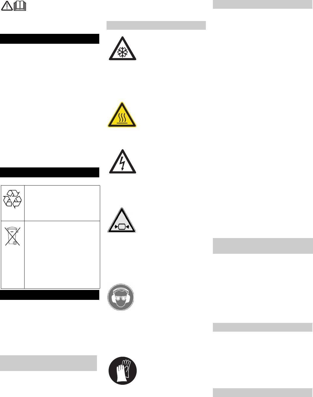
Gefahr
1 Arretierung
Erstickungsgefahr durch Kohlendioxid.
2 Mutter
Beim Betrieb des Gerätes steigt der Koh-
3 Abdeckung
lendioxidgehalt der Luft am Arbeitsplatz.
Arbeitsplatz ausreichend lüften, ggf. ein
Î Muttern der Abdeckung abschrauben.
Personenwarngerät verwenden.
Î Abdeckung abnehmen.
Anzeichen hoher Kohlendioxidkonzentrati-
Î Steuergerät einsetzen und festschrau-
on in der Atemluft:
ben.
– 3...5%: Kopfschmerzen, hohe Atemfre-
quenz.
– 7...10%: Kopfschmerzen, Brechreiz,
evtl. Bewusstlosigkeit.
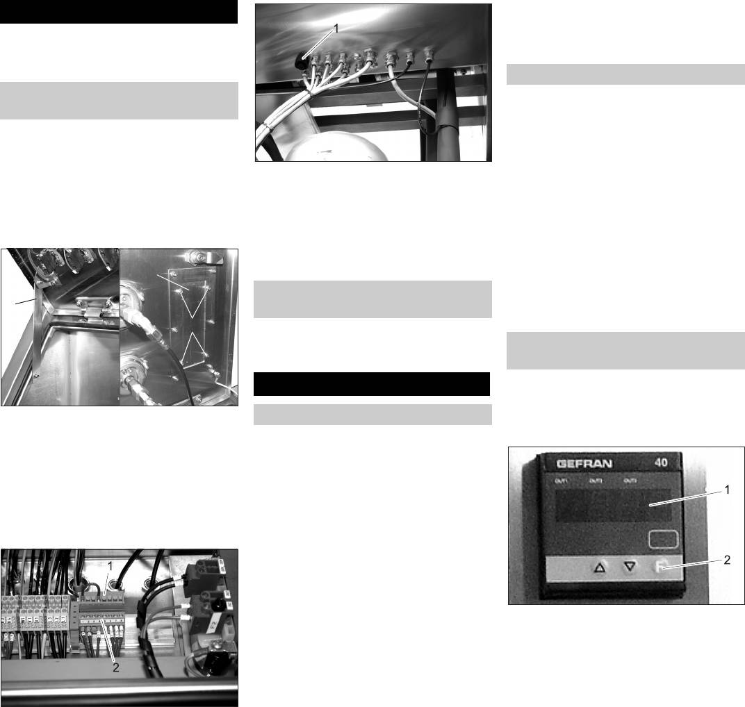
Beim Auftreten dieser Anzeichen sofort
1 Display
Gerät abstellen und an die frische Luft ge-
2 Taste „F“
hen, vor Fortsetzung der Arbeit Lüftungs-
maßnahmen verbessern .
Î Schlüsselschalter „0/OFF / 1/ON“ auf
Sicherheitsdatenblatt des Kohlendioxidher-
„1/ON“ stellen.
stellers beachten.
Î Leeren Behälter mittig auf die Waagen-
Gefahr
plattform stellen.
Gefahr von Kälteverbrennungen. Trocken-
Î Leergewicht (in kg) auf dem Display ab-
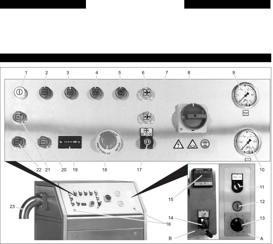
1 Blindstecker
eis hat eine Temperatur von -79 °C. Tro-
lesen.
2 Steckerleiste
ckeneis und kalte Geräteteile nie
Î Taste „F“ drücken.
ungeschützt berühren. Schutzhandschuhe
Î Leergewicht (in kg) mit den Pfeiltasten
Î Blindstecker aus der Steckerleiste her-
und Schutzkleidung tragen.
im Display einstellen.
ausziehen.
Gefahr
Î Taste „F“ drücken, bis im Display „CF“
Î Stecker des Steuergeräts an Stelle des
Verletzungsgefahr durch herausschießen-
angezeigt wird.
Blindsteckers einstecken.
de Trockeneis-Pellets. Pelletauswurf vor
Î Taste „F“ loslassen und nochmals drü-
Waage anschließen
Inbetriebnahme auf Sauberkeit prüfen.
cken.
Î Waagenplattform unterhalb des Pellet-
Nicht direkt auf die Extruderplatte schauen.
Im Display erscheint abwechselnd „H1“
auswurfs aufstellen und nivellieren.
Gefahr
und das eingestellte Leergewicht.
Hinweis
Berstgefahr. Trockeneis niemals in dicht
Î Zu produzierende Pelletmenge (in kg)
Darauf achten, dass die Waagenplattform
schließenden Behältern aufbewahren.
mit den Pfeiltasten im Display einstel-
frei steht und keine Gegenstände berührt,
Î Schlüsselschalter „M/0/A“ auf „A“ stel-
len.
da sonst die Gewichtsmessung ungenau
len. Schlüssel abziehen und so aufbe-
Î Taste „F“ drücken, bis das Leergewicht
wird.
wahren, dass er nur für das
angezeigt wird.
Î Verriegelungen der vorderen Geräteab-
Wartungspersonal zugänglich ist.
deckung öffnen.
Î Spannungsversorgung herstellen.
Î Abdeckung nach außen kippen und
Î Kohlendioxid-Zufuhr öffnen.
nach oben abnehmen.
Î Hauptschalter einschalten.
Deutsch 5
3
1
2
Manueller Betrieb
Anbausatz Mengenregelung PCS
montieren (Option)
Automatik-Betrieb mit Anbausatz
Waage (Option)
Betrieb
Inbetriebnahme
Produktionsmenge einstellen

Pellets herstellen
Außerbetriebnahme Extruderplatte wechseln
Î Taste „Ein“ drücken.
Î Kohlendioxid-Zufuhr absperren.
Zur Änderung des Pelletdurchmessers
Î Die Pelletproduktion beginnt.
Î Taste „Ein“ drücken und Gerät laufen
kann die Extruderplatte gewechselt wer-
Ist die eingestellte Pelletmenge herge-
lassen, bis das Manometer Kohlendio-
den.
stellt, beendet das Gerät die Produkti-
xid „0“ anzeigt.
on.
Gefahr!
Î Taste „Aus“ drücken.
Î Taste „Aus“ drücken.
Unfallgefahr bei Arbeiten am Gerät. Vor Ar-
Das Gerät führt den momentanen Pro-
Î Vollen Behälter von der Waage neh-
beiten am Gerät alle Arbeitsschritte des
duktionszyklus durch und beendet an-
men.
Kapitels „Außerbetriebnahme“ durchfüh-
schließend die Pelletproduktion.
ren.
Automatikbetrieb mit Anbausatz
Î Hauptschalter in Stellung „0“ drehen.
Gefahr
Mengenregelung PCS (Option)
Gefahr von Kälteverbrennungen durch Tro-
Im Automatikbetrieb werden eine voreinge-
ckeneis oder kalte Geräteteile. Bei Arbeiten
stellte Zeit lang Pellets hergestellt. An-
am Gerät geeignete Kälteschutzkleidung
schließend stoppt das Gerät die
tragen oder Trockeneis entfernen und Ge-
Pelletproduktion.
rät aufwärmen lassen.
Î Leeren Behälter unter den Pelletaus-
Körperkontakt mit Trockeneis vermeiden.
wurf stellen.
Trockeneis nie in den Mund nehmen.
Î Schlüsselschalter „Direkt/PCS“ auf
„PCS“ drehen.
Î Taste „Ein“ drücken.
Î Produktionszeit/-menge am Drehknopf
einstellen.
Î Taste PCS starten drücken.
Die Pelletproduktion beginnt.
Ist die eingestellte Zeit abgelaufen, stoppt
die Pelletproduktion.
Î Zur Wiederholung der Produktionszeit
Taste PCS starten erneut drücken.
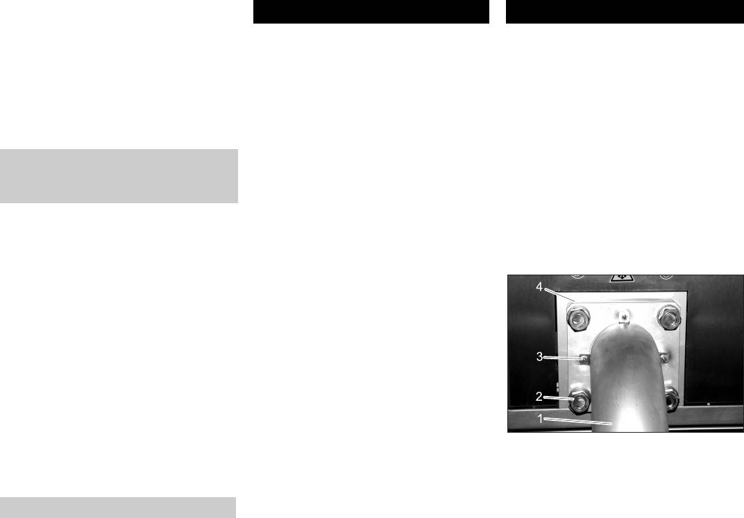
1 Pelletauswurf
Î Zur Beendigung der Produktion Taste
2 Mutter Extruderplatte
„Aus“ drücken.
3 Mutter Pelletauswurf
Ausschalten im Notfall
4 Extruderplatte
Î Not-Aus-Taster drücken.
Î Muttern Pelletauswurf abschrauben.
Î Pelletauswurf abnehmen.
Î Muttern Extruderplatte abschrauben.
Î Extruderplatte abnehmen.
Î Andere Extruderplatte in umgekehrter
Reihenfolge anbringen.
6 Deutsch

Wartung und Pflege
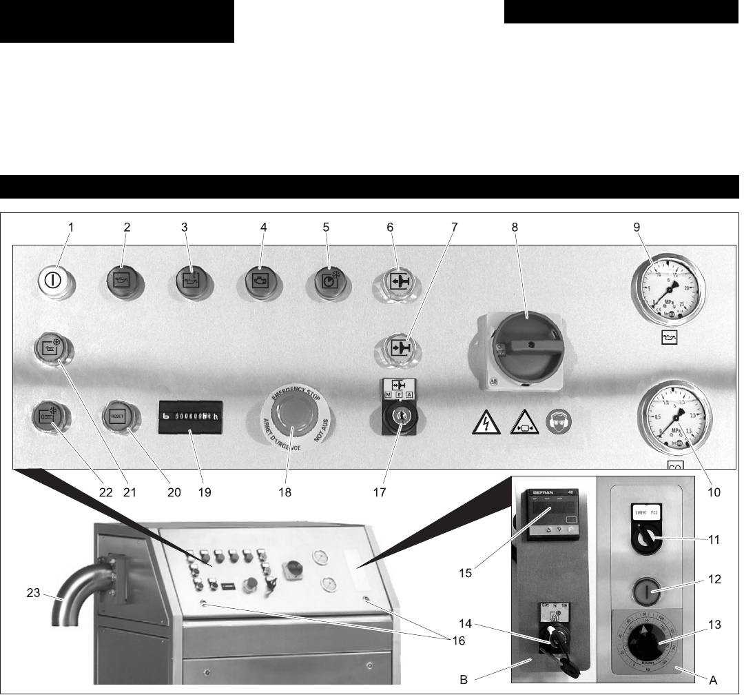
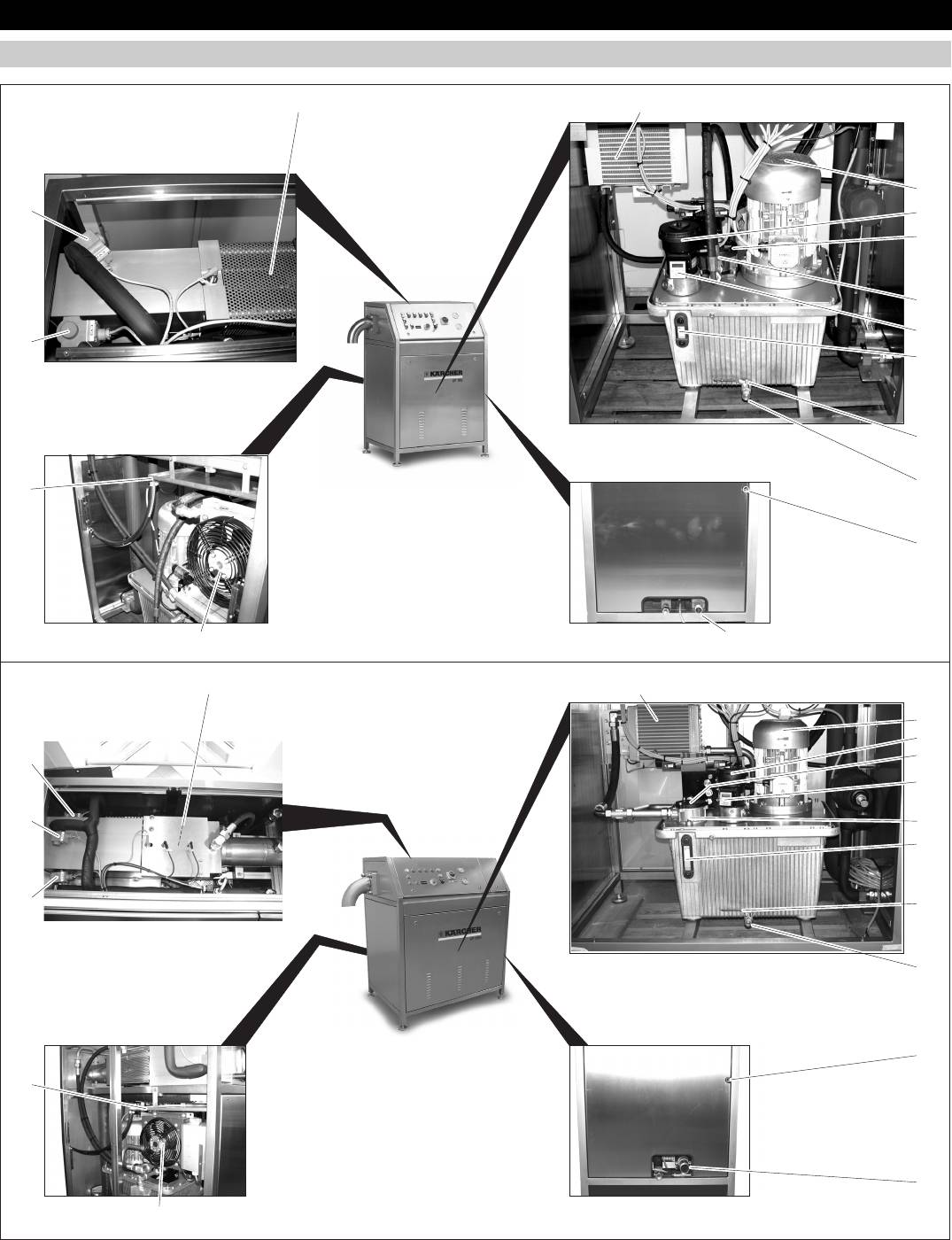
Geräteübersicht
1 Ölkühler
7 Ölstandsanzeige
13 Kondensatsammler
2 Lüfter Hydraulikmotor
8 Absperrventil
14 Magnetventil EV3
3 Luftfiltergehäuse
9 Ölablassschraube
15 Magnetventil EV2
4 Ölfilter
10 Kondensatableitung
16 Magnetventil EV4
5 Ölfiltergehäuse
11 Abgasleitung
17 Kolben
6 Temperaturanzeige Hydrauliköl
12 Ventilator Ölkühler
Deutsch 7
17
1
IP 120
2
16
3
4
5
6
15
7
8
9
13
10
1112
17
1
IP 220
2
3
16
4
6
15
5
7
14
8
9
10
13
11
12

Î Gerät einschalten und Ölstandsanzeige
Wartungshinweise
Nach den ersten 100 Betriebsstunden
bei laufendem Gerät prüfen. Bei Bedarf
Î Ölfilter erneuern.
Grundlage für eine betriebssichere Anlage
Öl nachfüllen.
Î Festen Sitz der Schrauben und Fittings-
ist die regelmäßige Wartung nach folgen-
prüfen, bei Bedarf nachziehen (An-
Ölwechsel ohne Ölwechselanlage
dem Wartungsplan.
zugsdrehmomente siehe Abschnitt
Den Ölwechsel nur ausführen, wenn das Öl
Reparatur- und Wartungsarbeiten müssen
„Anzugsdrehmomente“).
noch warm ist.
von autorisierten Fachkräften (Kärcher-
Alle 1000 Betriebsstunden
Gefahr
Service oder vom Hersteller eingewiese-
nes Personal) durchgeführt werden.
Î Kolben auf Kratzer oder Furchen prü-
Verbrennungsgefahr durch heißes Öl!
Verwenden Sie ausschließlich Original-Er-
fen, bei beschädigtem Kolben Kunden-
Vor dem Ölwechsel Öl auf ca. 40°C abküh-
satzteile des Herstellers oder von ihm emp-
dienst verständigen.
len lassen.
fohlene Teile, wie
Î Wanne zum Auffangen des Öls unter
Alle 2000 Betriebsstunden
– Ersatz- und Verschleissteile,
das Absperrventil stellen.
Î Hydrauliköl und Ölfilter erneuern (siehe
– Zubehörteile,
Î Ölablassschraube herausdrehen.
„Wartungsarbeiten“).
– Betriebsstoffe,
Î Absperrventil öffnen und Öl restlos ab-
Anzugsdrehmomente
– Reinigungsmittel.
laufen lassen.
Î Absperrventil schließen.
Gefahr!
M3 1,1 Nm
Î Ölablassschraube eindrehen und fest-
Unfallgefahr bei Arbeiten am Gerät. Vor Ar-
M4 2,5 Nm
ziehen.
beiten am Gerät alle Arbeitsschritte des
M5 5,1 Nm
IP 120:
Kapitels „Außerbetriebnahme“ durchfüh-
M6 8,8 Nm
Î Deckel vom Ölfiltergehäuse abschrau-
ren.
M8 21,4 Nm
ben.
Gefahr
M10 44 Nm
Î Ölfiltereinsatz wechseln.
Gefahr von Kälteverbrennungen durch Tro-
Î Deckel auf dem Ölfiltergehäuse fest-
ckeneis oder kalte Geräteteile. Bei Arbeiten
M12 88 Nm
schrauben.
am Gerät geeignete Kälteschutzkleidung
M14 119 Nm
Î Deckel vom Luftfiltergehäuse ab-
tragen oder Trockeneis entfernen und Ge-
M16 183 Nm
schrauben.
rät aufwärmen lassen.
M20 224 Nm
Î Luftfiltereinsatz herausnehmen.
Körperkontakt mit Trockeneis vermeiden.
Trockeneis nie in den Mund nehmen.
Gerät öffnen
Î Neues Öl eingießen bis die Ölstands-
anzeige zu 3/4 mit Öl gefüllt ist.
Wartungsvertrag
Gefahr!
Ölsorte und Füllmenge siehe „Techni-
Um einen zuverlässigen Betrieb der Anlage
Unfallgefahr bei Arbeiten am Gerät. Vor Ar-
sche Daten“.
zu gewährleisten, empfehlen wir Ihnen ei-
beiten am Gerät alle Arbeitsschritte des
Î Luftfiltereinsatz einlegen.
nen Wartungsvertrag abzuschließen. Wen-
Kapitels „Außerbetriebnahme“ durchfüh-
Î Deckel auf das Luftfiltergehäuse auf-
den Sie sich bitte an Ihren zuständigen
ren.
schrauben.
Kärcher-Kundendienst.
– Die Vordere Abdeckung kann nach Öff-
Î Gerät einschalten und Ölstandsanzeige
Wartungsplan
nen der beiden Verriegelungen nach
bei laufendem Gerät prüfen. Bei Bedarf
außen gekippt und nach oben abge-
Öl nachfüllen.
Täglich
nommen werden.
IP 220:
Î Auffangbehälter unter die Kondensa-
– Die anderen Abdeckungen können
Î Deckel vom Ölfiltergehäuse abschrau-
tableitung stellen und regelmäßig lee-
nach dem Herausdrehen der Schrau-
ben.
ren.
ben abgenommen werden.
Î Ölfiltereinsatz herausnehmen.
Wöchentlich
Wartungsarbeiten
Î Neues Öl eingießen bis die Ölstands-
Î Ölstand kontrollieren. Die Ölstandsan-
anzeige zu 3/4 mit Öl gefüllt ist.
zeige muss zu 3/4 mit Öl gefüllt sein.
Ölwechsel mit Ölwechselanlage
Ölsorte und Füllmenge siehe „Techni-
Î Sichtprüfung Ölkühler. Ölkühler und
Den Ölwechsel nur ausführen, wenn das Öl
sche Daten“.
Luftein- und auslass müssen sauber
noch warm ist.
Î Neuen Ölfiltereinsatz einsetzen.
sein. Bei Bedarf reinigen oder mit
Gefahr
Î Deckel auf das Ölfiltergehäuse auf-
Druckluft ausblasen.
Verbrennungsgefahr durch heißes Öl!
schrauben.
Î Funktion des Ventilators Ölkühler prü-
Vor dem Ölwechsel Öl auf ca. 40°C abküh-
Î Gerät einschalten und Ölstandsanzeige
fen, bei Bedarf reinigen. Der Ventilator
len lassen.
bei laufendem Gerät prüfen. Bei Bedarf
muss in Betrieb gehen, wenn die Öl-
Î Ölablassschraube herausdrehen.
Öl nachfüllen.
temperatur 45°C erreicht.
Î Ölwechselanlage mit dem Absperrven-
Î Sichtkontrolle des Lüfters Hydraulikmo-
Kolben prüfen
til verbinden.
tor, bei Bedarf reinigen.
Î Deckel des Gerätes abnehmen.
Î Absperrventil öffnen.
Î Funktion der Ventile EV2, EV3 und
Î Schlüsselschalter „M/0/A“ auf „M“ stel-
Î Öl mit einer Ölwechselanlage restlos in
EV4* prüfen. Bei geöffnetem Ventil sind
len.
einen Auffangbehälter pumpen.
Strömungsgeräusche hörbar.
Î Taste „Kolben zurück“ drücken.
Î Deckel vom Ölfiltergehäuse abschrau-
Î Kohlendioxid-Leitungen auf Dichtheit
Der Kolben fährt in die hinterste Stel-
ben.
prüfen, bei Undichtheit Kundendienst
lung.
Î Ölfiltereinsatz wechseln.
rufen.
Î Kolben auf Kratzer und Furchen prüfen.
Î Deckel auf dem Ölfiltergehäuse fest-
Î Schlüsselschalter „M/0/A“ auf „A“ stel-
schrauben.
* nur IP 220
len. Schlüssel abziehen und so aufbe-
Î Neues Öl mit der Ölwechselanlage in
Monatlich
wahren, dass er nur für das
das Gerät füllen, bis die Ölstandsanzei-
Î Hydraulische Anlage auf Dichtheit prü-
Wartungspersonal zugänglich ist.
ge zu 3/4 mit Öl gefüllt ist.
fen (Schläuche, Leitungen, Verbindun-
Ölsorte und Füllmenge siehe „Techni-
gen). Undichtigkeiten beheben.
sche Daten“.
Î Gerät innen und außen reinigen.
8 Deutsch

Hilfe bei Störungen
Gefahr!
Unfallgefahr bei Arbeiten am Gerät. Vor Ar-
beiten am Gerät alle Arbeitsschritte des
Kapitels „Außerbetriebnahme“ durchfüh-
ren.
Gefahr
Gefahr von Kälteverbrennungen durch Tro-
ckeneis oder kalte Geräteteile. Bei Arbeiten
am Gerät geeignete Kälteschutzkleidung
tragen oder Trockeneis entfernen und Ge-
rät aufwärmen lassen.
Körperkontakt mit Trockeneis vermeiden.
Trockeneis nie in den Mund nehmen.
Störungen mit Anzeige
Störung Mögliche Ursache Behebung Durch wen
Kontrollleuchte „Ölni-
Hydrauliksystem undicht Hydrauliksystem auf Dichtheit prüfen. Bei Un-
Bediener
veau tief“ leuchtet
dichtigkeit Gerät außer Betrieb nehmen und
Kundendienst verständigen.
Ölstandsensor defekt Ölstandsanzeige prüfen. Ist der Ölstand in Ord-
Bediener
nung, Kundendienst verständigen.
Kontrollleuchte „Öl-
Ventilator Ölkühler arbeitet nicht richtig Ventilator Ölkühler auf Funktion prüfen, bei Be-
Bediener
temperatur hoch“
darf reinigen. Bei Defekt Kundendienst verstän-
leuchtet
digen.
Temperaturschalter defekt Kundendienst verständigen. Bediener
Kontrollleuchte „Motor
Taste „Reset“ drücken. Gerät neu starten. Tritt
Bediener
Überlast“ leuchtet
das Problem weiterhin auf, Kundendienst ver-
ständigen.
Kontrollleuchte „Zy-
Keine Extrusion Extruderplatte und Kolben auf Beschädigung
Bediener
klus zu lang“ leuchtet
prüfen, bei Beschädigung Kundendienst ver-
ständigen.
Positionssensor defekt Kundendienst verständigen. Bediener
Drehrichtung der Hydraulikpumpe falsch Elektrischen Anschluss prüfen. Kunden-
dienst
Störungen ohne Anzeige
Störung Mögliche Ursache Behebung Durch wen
Keine Trockeneis-
Kein flüssiges Kohlendioxid in der Zuleitung Warten, bis flüssiges Kohlendioxid das Gas aus
Bediener
schnee-Produktion
der Leitung verdrängt hat.
Ventile EV2, EV3, EV4 *sind blockiert oder
Wenn die Magnetventile korrekt arbeiten, ist bei
Bediener
defekt.
abgestellter Kohlendioxidversorgung ein Kli-
* nur IP 220
cken zu hören. Bei Bedarf Kundendienst ver-
ständigen.
Kohlendioxid-Druck zu hoch IP 120: Druck an der Kohlendioxid-Versorgung
Bediener
einstellen (Wert siehe „Technische Daten“).
IP 220: Druck am Manometer prüfen. Ist der
Druck über 2,1 MPa (21 bar) Kundendienst ver-
ständigen.
Zu viel Trockeneis-
Ventile EV2, EV3, EV4* schließen nicht.
Kundendienst verständigen. Bediener
schnee in der Abgas-
* nur IP 220
leitung
Sinterbüchse defekt. Kundendienst verständigen. Bediener
Aus dem Gerät tropft
Abfluss im Kondensatsammler oder Kon-
Abfluss und Kondensatleitung reinigen. Bediener
Wasser
densatleitung verstopft.
Deutsch 9

Technische Daten
IP 120 IP 220
Elektrischer Anschluss
Spannung V 400 400
Stromart 3~ 3~
Frequenz Hz 50 50
Anschlussleistung kW 4,0 5,6
Maximal zulässige Netzimpedanz Ohm 0.147+j0.092 0.169+j0.106
Trockeneis
Versorgungsdruck, flüssiges Kohlendioxid MPa (bar) 1,6...2,1 (16...21) 1,3...2,1 (13...21)
Maximaler Feuchtigkeitsgehalt, flüssiges Kohlendioxid ppm 66 66
Ölgehalt, flüssiges Kolendioxid abslout ölfrei abslout ölfrei
Durchmesser der Trockeneispellets mm 3 3
Pelletproduktion, max. kg/h 120 220
Förderdruck flüssiges Kohlendioxid für maximale Pelletproduktion MPa (bar) 1,75 (17,5) 1,7 (17)
Abmessungen
Breite mm 1320 1560
Tiefe mm 700 800
Höhe mm 1439 1400
Gewicht, leer kg 340 495
Gewicht, voll kg 360 540
Schalldruckpegel (EN 60704-1) dB(A) 85 89
Hydrauliköl nach DIN 51524, Teil 2
Qualität 16/13 gemäß ISO 4406
Viskosität ISO VG 32 ISO VG 32
Ölmenge l 35 60
Zubehör
Ersatzteile
Produkt: Trockeneispelletizer
Typ: 1.574-xxx
– Es dürfen nur Zubehör und Ersatzteile
Bestell-Nr.
verwendet werden, die vom Hersteller
Einschlägige EG-Richtlinien
CO
2
Detektor 6.574-105.0
freigegeben sind. Original-Zubehör und
98/37/EG
Original-Ersatzteile bieten die Gewähr
2006/95/EG
Waage 600x800 mm mit
6.574-179.0
2004/108/EG
dafür, dass das Gerät sicher und stö-
Steuerung
Angewandte harmonisierte Normen
rungsfrei betrieben werden kann.
EN 55014–1: 2006
Waage 1000x1000 mm
6.574-180.0
– Eine Auswahl der am häufigsten benö-
EN 55014–2: 1997 + A1: 2001
mit Steuerung
tigten Ersatzteile finden Sie am Ende
EN 626–1
der Betriebsanleitung.
EN 60204–1
Hydrauliköl, 20 l 6.288-223.0
– Weitere Informationen über Ersatzteile
EN 61000-3-2: 2006
erhalten Sie unter www.kaercher.com
EN 61000–3–3: 1995 + A1: 2001 + A2:
im Bereich Service.
2005
IP 120
EN 61000–3–11: 2000
Garantie
Angewandte nationale Normen
Bestell-Nr.
-
In jedem Land gelten die von unserer zu-
Extruderplatte 16 mm 6.574-060.0
ständigen Vertriebsgesellschaft herausge-
Die Unterzeichnenden handeln im Auftrag
gebenen Garantiebedingungen. Etwaige
Extruderplatte 3 mm 6.574-061.0
und mit Vollmacht der Geschäftsführung.
Störungen an Ihrem Gerät beseitigen wir
Extruderplatte 1,7 mm 6.574-200.0
innerhalb der Garantiefrist kostenlos, so-
fern ein Material- oder Herstellungsfehler
Mengenregelung
6.574-181.0
die Ursache sein sollte. Im Garantiefall
PCS 120
wenden Sie sich bitte mit Kaufbeleg an Ih-
Ersatzteilpaket 6.574-175.0
ren Händler oder die nächste autorisierte
Alfred Kärcher GmbH & Co. KG
Kundendienststelle.
Alfred Kärcher-Str. 28 - 40
D - 71364 Winnenden
IP 220
CE-Erklärung
Tel.: +49 7195 14-0
Fax: +49 7195 14-2212
Hiermit erklären wir, dass die nachfolgend
Bestell-Nr.
bezeichnete Maschine aufgrund ihrer Kon-
Extruderplatte 16 mm 6.574-002.0
zipierung und Bauart sowie in der von uns
in Verkehr gebrachten Ausführung den ein-
Mengenregelung
6.574-178.0
schlägigen grundlegenden Sicherheits-
PCS 220
und Gesundheitsanforderungen der EG-
Ersatzteilpaket 6.574-176.0
Richtlinien entspricht. Bei einer nicht mit
uns abgestimmten Änderung der Maschine
verliert diese Erklärung ihre Gültigkeit.
10 Deutsch
CEO
Head of Approbation
Please read and comply with
Notice
General notes on safety
these instructions prior to the
Indicates operating idea and important in-
Danger
initial operation of your appliance. Retain
formation.
these operating instructions for future refer-
Risk of suffocation on account of carbon di-
Symbols on the machine
ence or for subsequent possessors.
oxide. The dry ice pellets are made of solid-
ified carbon dioxide. The carbon dioxide
Contents
content in the air at the place where the ma-
Environmental protection 11
chine is used will increase when the ma-
chine is running. Ensure adequate
Safety instructions 11
ventilation at the place of use; if possible,
Proper use 12
Danger
use an alarm to warn persons. Symptoms
Function 12
of high levels of carbon dioxide in the air
Risk of cold burns. Dry ice has a tempera-
Control elements 12
that is breathed in:
ture of -79 °C. Never touch dry ice or cold
Mounting the installation set scale (option)
– 3...5%: headache, faster breathing.
parts of the machine without appropriate
13
protection.
– 7...10%: headache, nausea and per-
Operation 13
haps even unconsciousness.
If any of these symptoms occur, please
Shutting down 14
switch off the machine immediately and get
Replace the extruder plate. 14
a breath of fresh air and improve the venti-
Maintenance and care 15
lation before starting work again with the
Troubleshooting 17
machine.
Danger
Technical specifications 18
Follow the safety specifications of the man-
Risk of burns! Beware of hot components.
Accessories 18
ufacturer of carbon dioxide.
Warranty 18
Danger
CE declaration 18
Risk of injury if the machine is left running in
an unattended state. Disconnect the mains
Environmental protection
plug from the socket before performing any
Danger
work.
Risk of injury on account of electric shock.
Danger
The packaging material can be
recycled. Please do not place
Pull the plug out of the socket before open-
Risk of cold burns on account of dry ice or
the packaging into the ordinary
ing the control cabinet.
cold parts of the machine. While working on
refuse for disposal, but ar-
the machine, wear appropriate safety gear
range for the proper recycling.
for protection against cold or remove dry ice
and let the machine heat up.
Old appliances contain valua-
Avoid bodily contact with dry ice.
ble materials that can be recy-
Never put dry ice in your mouth.
cled. Please arrange for the
Danger
First aid in case of accidents involv-
proper recycling of old appli-
Risk of injury by emerging hydraulic oil
ances. Batteries, oil, and simi-
ing dry ice or liquid carbon dioxide
stream.
lar substances must not enter
Never operate the machine while the hous-
Ingestion
the environment. Please dis-
ing is open. Immediately take the machine
Î Seek immediate medical attention.
pose of your old appliances us-
out of service if the hydraulic system is leak-
ing appropriate collection
Contact with eye
ing.
systems.
Î Flush eye with plenty of warm water and
seek medical attention immediately.
Safety instructions
Contact with skin
The appliance may only be operated by
Î Flush affected skin with plenty of warm
persons who have read and understood the
water for at least 15 minutes and seek
Danger
contents of this operating instrucions
medical attention immediately.
maual. Please ensure that you conform to
Risk of injury on account of flying dry ice
Specifications and Guidelines
all the safety instructions and regulations.
pellets or dirt particles. Wear close fitting
Î This operating instructions manual must
safety goggles.
For the operation of this system the follow-
be stored in such a way that it can be
Risk of hearing impairment. Wear ear-pro-
ing regulations and directives are applica-
easily accessed by the operator.
tection aids.
ble in the Federal Republic of Germany
(available from Carl Heymanns Verlag KG,
Symbols used in the operation in-
Luxemburger Straße 449, 50939 Cologne):
struction
– BGR 189 Using safety gear
The following symbols are used in this op-
– BGR 195 Using of safety gloves
erating manual:
– BGI 836 Gas warner
Danger!
Danger
Switch-off in case of emergency
Indicates an immediate danger. By not pay-
Risk of injury on account of flying dry ice
Î Press emergency-stop button.
ing attention to this notice, there is danger
pellets.
of death or serious injury.
The machine is immediately shut off.
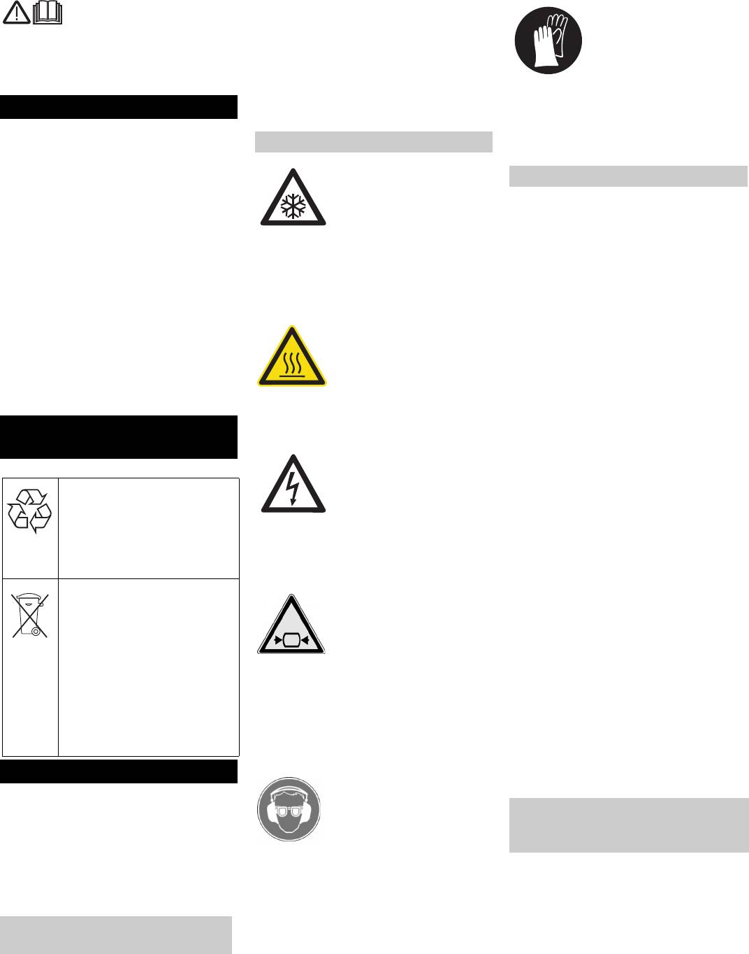
Wear protective gloves as per EN 511.
몇 Warning
Indicates a possible dangerous situation.
By not paying attention to the notice, light
injuries or property damage may possibly
occure.
English 11
Do not spray the machine with water to
Proper use Function
clean it. Wipe the machine housing using a
The machine produces dry ice pellets con-
damp cloth.
Liquid carbon dioxide streams into the cyl-
sisting of liquid carbon dioxide. The size of
The application may only be installed by
inder and hardens into dry ice snow by the
the dry ice pellets is selected via different
authorised technicians!
drop in pressure. This dry ice snow is com-
extruder plates.
몇 Warning
pacted by a hydraulic cylinder and pressed
The machine is only to be used in dry
through the extruder plate. This creates cy-
The highest allowed net impedance at the
rooms.
lindrical dry ice sticks, which breaks down
electrical connection point (refer to techni-
into pellets.
cal data) is not to be exceeded.
Control elements
1 Indicator lamp "Voltage on"
15 Weight indicator (option)
2 Indicator lamp "Oil level low"
16 Switch cabinet lock
3 Indicator lamp "Oil temperature high"
17 Key switch "M/0/A".
4 Indicator lamp "Motor overload"
M: The piston can be moved manually
5 Indicator lamp "Cycle too long"
to perform service work.
Refer to "Help with malfunctions/errors
0: The machine is turned off.
with display".
A: Pellet production.
6 Key "Piston forward"
18 Emergency-stop button
The piston is manually moved into the
19 Operating hour counter
front position (prerequisite: key switch
20 Key "Reset"
at “M”).
Resets the automatic operation inter-
7 Key "Piston backwards"
ruption following a malfunction.
The piston is manually moved into the
21 Key "On"
rearmost position (prerequisite: key
22 Key "Off"
switch at “M”).
The piston stroke is terminated; the pis-
8 Main switch
ton will move to the front position and
9 Oil pressure manometer
machine will stop.
10 Steam pressure manometer
23 Pellet ejector
11 Key switch "Direct/PCS" (option)
A Installation set volume control PCS (op-
12 Key "Start PCS" (option)
tion)
13 Rotary knob "Production time/volume
B Installation set scale (option)
(option)
14 Set the key switch to "0/OFF" / "I/ON"
(option).
12 English
Î Release emergency-stop button by
Install attachment sets
turning.
몇
Warning
The indicator lamp "Voltage on" will illu-
minate.
Installation sets must only be installed by
authorized personnel.
Mounting the installation set scale
Î Place an empty container below the pel-
(option)
let ejector.
Î If the installation set "Scale" has been
Installing the control
installed, set the key switch "On/Off" to
Danger
"Off".
Risk of injury on account of electric shock.
1Plug
Î If the installation set "Volume control"
Pull the plug out of the socket before open-
has been installed, set the key switch
ing the control cabinet.
Î Guide the scale platform cable into the
"Direct/PCS" to "Direct".
Î Open the switch cabinet locks, swivel
machine from the bottom and connect
Î Press "On" key.
cover upward and latch.
the plug on the bottom of the switch
The pellet production will start.
cabinet.
Î Once the desired quantity of pellets has
Î Close and lock the machine cover.
been produced, press the "Off" key.
The machine will finish the current pro-
duction cycle and will then terminate the
pellet production.
The volume control is installed just like the
control of the installation set "Scale".
The scale does not need to be connected.
In automatic mode, a preset quantity of pel-
lets is produced. After that, the machine will
terminate the pellet production.
1Lock
2Nut
Danger
3Cover
Risk of suffocation on account of carbon di-
oxide. The carbon dioxide content in the air
Î Remove the nuts on the cover.
at the place where the machine is used will
Î Remove cover.
increase when the machine is running. En-
Î Insert the control and fasten it with
sure adequate ventilation at the place of
screws.
use; if possible, use an alarm to warn per-
sons. Symptoms of high levels of carbon di-
oxide in the air that is breathed in:
– 3...5%: headache, faster breathing.
– 7...10%: headache, nausea and per-
haps even unconsciousness.
1Display
If any of these symptoms occur, please
2 "F" key
switch off the machine immediately and get
a breath of fresh air and improve the venti-
Î Set the key switch "0/OFF" / "I/ON" to
lation before starting work again with the
"1/ON" (option).
machine.
Î Center an empty container on the scale
Follow the safety specifications of the man-
platform.
1 Dummy connector
ufacturer of carbon dioxide.
Î Read its empty weight (in kg) on the dis-
2 Power strip
Danger
play.
Risk of cold burns. Dry ice has a tempera-
Î Press "F" key.
Î Pull the dummy connector out of the
ture of -79 °C. Never touch dry ice or cold
Î Set its empty weight (in kg) on the dis-
power strip.
parts of the machine without appropriate
play using the arrow keys.
Î Insert the control plug instead of the
protection. Wear protective gloves and pro-
Î Press "F" key until "CF" is shown on the
dummy connector.
tective overalls.
display.
Connecting the scale
Danger
Î Release the "F" key and press it once
Î Install the scale platform below the pel-
Risk of injury on account of ejected dry ice
again.
let ejector and level.
pellets. Inspect the pellet ejector for cleanli-
The display shows "H1" and the set
Note
ness prior to taking it into operation. Do not
empty weight (alternating).
look directly at the extruder plate.
Make sure that the scale platform is free-
Î Set the pellet quantity to be produced
standing and not obstructed by any objects,
Danger
(in kg) on the display using the arrow
as this will cause inaccurate measure-
Danger of bursting. Never store dry ice in
keys.
ments.
tightly sealed containers.
Î Press "F" key until the empty weight is
Î Open both latches on the front machine
Î Set the key switch "M/0/A" to "A". Re-
shown on the display.
cover.
move the key and store so that it can
Î Tilt the cover toward the outside and lift
only be accessed by service personnel.
off from the top.
Î Switch on the power supply.
Î Open the carbon dioxide supply.
Î Turn on the main switch.
English 13
3
1
2
Manual operation
Mounting the installation set "Vol-
ume control PCS" (option)
Automatic operation with the instal-
lation set "Scale" (option)
Operation
Start up
Setting the quantity to be produced
Producing pellets
Shutting down Replace the extruder plate.
Î Press "On" key.
Î Shut off the carbon dioxide supply.
The extruder plate can be replaced to
Î The pellet production will start.
Î Press the "On" key and let the machine
change the pellet diameter.
Once the desired quantity of pellets has
run until the manometer displays "Car-
been produced, the machine will switch
Danger!
bon dioxide 0".
off.
Risk of accident while working on the appli-
Î Press "Off" key.
Î Press "Off" key.
ance. Carry out all the steps described in
The machine will finish the current pro-
Î Remove the full container from the
the chapter "Shut down" before starting
duction cycle and will then terminate the
scale.
anhy work on the device.
pellet production.
Danger
Automatic operation with the instal-
Î Turn the main switch to position "0"
Risk of cold burns on account of dry ice or
lation set "Volume control PCS"
cold parts of the machine. While working on
(option)
the machine, wear appropriate safety gear
In automatic mode, pellets are produced for
for protection against cold or remove dry ice
a preset length of time. After that, the ma-
and let the machine heat up.
chine will terminate the pellet production.
Avoid bodily contact with dry ice.
Î Place an empty container below the pel-
Never put dry ice in your mouth.
let ejector.
Î Rotate the key switch "Direct/PCS" to
"PCS".
Î Press "On" key.
Î Use the rotary knob to set the produc-
tion time/volume.
Î Press the key "Start PCS".
The pellet production will start.
Once the preset time has elapsed, the pro-
duction of the pellets will be terminated.
Î Press the key "Start PCS" once again in
1 Pellet ejector
order to repeat this production time pe-
2 Extruder plate nut
riod.
3 Pellet ejector nut
Î Press "Off" key to end production.
4 Extruder plate
Switch-off in case of emergency
Î Press emergency-stop button.
Î Unscrew the pellet ejector nut.
Î Remove the pellet ejector.
Î Unscrew the extruder plate nuts.
Î Remove the extruder plate.
Î Insert the other extruder plate in reverse
sequence.
14 English
Maintenance and care
Overview of the device
1 Oil cooler
7 Oil level indicator
13 Condensate collector
2 Hydraulic motor ventilator
8 Locking valve
14 Solenoid valve EV3
3 Air filter housing
9 Oil drain screw
15 Solenoid valve EV2
4 Oil filter
10 Condensate drain
16 Solenoid valve EV4
5 Oil filter housing
11 Exhaust line
17 Piston
6 Hydraulic oil temperature display
12 Oil cooler ventilator
English 15
17
1
IP 120
2
16
3
4
5
6
15
7
8
9
13
10
1112
17
1
IP 220
2
3
16
4
6
15
5
7
14
8
9
10
13
11
12

Î Switch on the machine and check the oil
Maintenance instructions
After the first 100 operating hours
level indicator while the machine is run-
Î Install new oil filter.
The bases of a safe operating of the equip-
ning. If required, top up oil carefully.
Î Check that screws and fittings are firmly
ment is thr regularly maintenance accord-
screwed in, tighten if necessary (tor-
Oil change without oil change system
ing to the following maintenance plan.
ques are listed in the section "tightening
Only change the oil while it is still warm.
Repair and maintenance works must be
torques").
Danger
carried out by authorized qualified person-
nel (Kärcher service or personnel trained by
Every 1000 operating hours
Risk of burns due to hot oil!
the manufacturer).
Î Check the pistons for scratches and
Let the oil cool down to approx. 40 °C prior
Use exclusively original parts of the manu-
grooves; contact customer service if
to changing the oil.
facturer or those parts recommended by
piston is damaged.
Î Place a pan underneath the locking
him like
valve to catch the oil.
Every 2000 operating hours
– parts and wearing parts,
Î Turn out the oil drain screw.
Î Replace the hydraulic oil and oil filter
– accessories parts,
Î Open the locking valve and let all the oil
(see "Maintenance Procedures").
– operating materials,
drain.
Tightening torques
– cleaning agents.
Î Close locking tap.
Î Fix in the oil drain screw and tighten it.
Danger!
M3 1.1 Nm
IP 120:
Risk of accident while working on the appli-
Î Unscrew the lid from the oil filter hous-
ance. Carry out all the steps described in
M4 2.5 Nm
ing.
the chapter "Shut down" before starting
anhy work on the device.
M5 5.1 Nm
Î Change the oil filter inlay.
Î Attach the lid to the oil filter housing.
Danger
M6 8.8 Nm
Î Unscrew the lid from the air filter hous-
Risk of cold burns on account of dry ice or
M8 21.4 Nm
ing.
cold parts of the machine. While working on
Î Take out the air filter sieve.
the machine, wear appropriate safety gear
M10 44 Nm
for protection against cold or remove dry ice
Î Fill in new oil until the oil level indicator
M12 88 Nm
and let the machine heat up.
shows 3/4 full.
Avoid bodily contact with dry ice.
For oil type refer to technical specifica-
M14 119 Nm
Never put dry ice in your mouth.
tions.
M16 183 Nm
Î Install the air filter insert.
Maintenance contract
Î Screw the lid onto the air filter housing.
In order to guarantee a reliable operation og
M20 224 Nm
the equipment, we success, you signed a
Î Switch on the machine and check the oil
maintenance agreement. Please refer to
Opening the device
level indicator while the machine is run-
you local Kärcher service department.
ning. If required, top up oil carefully.
Danger!
IP 220:
Maintenance schedule
Risk of accident while working on the appli-
Î Unscrew the lid from the oil filter hous-
ance. Carry out all the steps described in
ing.
Daily
the chapter "Shut down" before starting
Î Place the collection container under the
Î Take out the oil filter insert.
anhy work on the device.
condensate drain and empty on a regu-
Î Fill in new oil until the oil level indicator
– The front cover can be tilted outward
lar basis.
shows 3/4 full.
and removed after the two locks have
For oil type refer to technical specifica-
Weekly
been released.
tions.
Î Check oil level. The oil level indicator
– The other covers can be removed once
Î Insert a new oil filter insert.
must be filled with 3/4 with oil.
the screws have been taken off.
Î Screw the lid onto the oil filter housing.
Î Visual inspection of oil cooler. The oil
Maintenance Works
Î Switch on the machine and check the oil
cooler and the air inlet and outlet must
level indicator while the machine is run-
be clean. Clean or blow out with com-
Oil change with oil change system
ning. If required, top up oil carefully.
pressed air if necessary.
Only change the oil while it is still warm.
Î Check ventilator function of oil cooler,
Check piston
Danger
clean if required. The ventilator must
Î Remove the cover from the machine.
Risk of burns due to hot oil!
start up as soon as the oil temperature
Î Set the key switch "M/0/A" to "M".
Let the oil cool down to approx. 40 °C prior
reaches 45°C.
Î Press the key "Piston backwards".
to changing the oil.
Î Visual check of the hydraulic motor ven-
Î Turn out the oil drain screw.
The piston moves back into the rear-
tilator, clean if required.
most position.
Î Connect the oil change system to the
Î Check the function of the valves EV2,
locking valve.
Î Check the piston for scratches and
EV3 and EV4*. When the valve is open
grooves.
Î Open locking tap.
you will hear streaming noises.
Î Set the key switch "M/0/A" to "A". Re-
Î Pump all the oil into a reservoir using
Î Check the carbon dioxide lines for tight-
move the key and store so that it can
the oil change system.
ness, call customer service in case of
only be accessed by service personnel.
Î Unscrew the lid from the oil filter hous-
leaks.
ing.
Î Change the oil filter inlay.
* IP 220 only
Î Attach the lid to the oil filter housing.
Monthly
Î Fill the machine with new oil using the
Î Check the hydraulic system for tight-
oil change system until the oil level indi-
ness (hoses, piping, connections). Fix
cator shows 3/4 full.
the leaks.
For oil type refer to technical specifica-
Î Clean the inside and outside of the ma-
tions.
chine.
16 English

Troubleshooting
Danger!
Risk of accident while working on the appli-
ance. Carry out all the steps described in
the chapter "Shut down" before starting
anhy work on the device.
Danger
Risk of cold burns on account of dry ice or
cold parts of the machine. While working on
the machine, wear appropriate safety gear
for protection against cold or remove dry ice
and let the machine heat up.
Avoid bodily contact with dry ice.
Never put dry ice in your mouth.
Faults with display
Fault Possible cause Remedy By whom
The indicator lamp
Hydraulic system is leaking Check the hydraulic system for tightness. Take
Operator
"Oil level low" illumi-
the machine out of service if the hydraulic sys-
nates
tem is leaking and contact customer service.
Defective oil level indicator Check the oil level indicator. If the oil level is not
Operator
OK, inform customer service.
Indicator lamp "Oil
The oil cooler ventilator is not functioning
Check ventilator function of oil cooler, clean if
Operator
temperature high" illu-
properly
required. Call customer service in case of de-
minates
fects.
Defective temperature switch Inform Customer Service. Operator
Indicator lamp "Motor
Press "Reset" key. Restart the machine. If the
Operator
overload" illuminates
fault recurs, call customer service.
Indicator lamp "Cycle
No extrusion Check the extruder plate and the pistons for
Operator
too long" illuminates
damage; contact customer service if damaged.
Defective positioning sensor Inform Customer Service. Operator
Direction of rotation of the hydraulic pump is
Check the electrical connection. Customer
wrong.
Service
Faults without display
Fault Possible cause Remedy By whom
No dry ice snow pro-
No liquid carbon dioxide in the supply line Wait until the liquid carbon dioxide has dis-
Operator
duction
placed the gas in the line.
Valves EV2, EV3, EV4 * are blocked or de-
If the solenoid valves are functioning properly,
Operator
fective.
there will be an audible click when the carbon di-
* IP 220 only
oxide supply is switch off. Call customer service
if necessary.
Carbon dioxide pressure too high IP 120: Adjust the pressure on the carbon diox-
Operator
ide supply (value is listed in "Specifications").
IP 220: Check pressure at the manometer. If the
pressure is higher than 2.1 MPa (21 bars), in-
form customer service.
Too much dry ice
Valves EV2, EV3, EV4 * do not close.
Inform Customer Service. Operator
snow in the exhaust
* IP 220 only
line
Sintered bushing defective. Inform Customer Service. Operator
Water is dripping from
Drain in the condensate collector or in the
Clean the drain and the condensate line. Operator
the machine
condensate line plugged.
English 17
Technical specifications
IP 120 IP 220
Electrical connection
Voltage V 400 400
Current type 3~ 3~
Frequency Hz 50 50
Connected load kW 4,0 5,6
Maximum allowed net impedance Ohm 0.147+j0.092 0.169+j0.106
Dry ice
Supply pressure, liquid carbon dioxide MPa (bar) 1,6...2,1 (16...21) 1,3...2,1 (13...21)
Max. moisture content, liquid carbon dioxide ppm 66 66
Oil content, liquid carbon dioxide absolutely free of oil absolutely free of oil
Diameter of dry ice pellets mm 3 3
Max. pellet production kg/h 120 220
Feed pressure for liquid carbon dioxide for max. pellet production MPa (bar) 1,75 (17,5) 1,7 (17)
Dimensions
Width mm 1320 1560
Depth mm 700 800
Height mm 1439 1400
Weight, empty kg 340 495
Weight, full kg 360 540
Sound pressure level (EN 60704-1) dB(A) 85 89
Hydraulic oil as per DIN 51524, part 2
Quality 16/13 as per ISO 4406
Viskosity ISO VG 32 ISO VG 32
Amount of oil l 35 60
Accessories
Spare parts
Product: Dry ice pelletiser
Type: 1.574-xxx
– Only use accessories and spare parts
Order No.
which have been approved by the man-
Relevant EU Directives
ufacturer. The exclusive use of original
98/37/EC
CO
2
Detector 6.574-105.0
accessories and original spare parts en-
2006/95/EC
2004/108/EC
Scale 600x800 mm with
6.574-179.0
sures that the appliance can be operat-
Applied harmonized standards
control
ed safely and troublefree.
EN 55014–1: 2006
– At the end of the operating instructions
EN 55014–2: 1997 + A1: 2001
Scale 1000x1000 mm with
6.574-180.0
you will find a selected list of spare parts
EN 626–1
control
that are often required.
EN 60204–1
Hydraulic oil, 20 l 6.288-223.0
– For additional information about spare
EN 61000-3-2: 2006
parts, please go to the Service section
EN 61000–3–3: 1995 + A1: 2001 + A2:
at www.kaercher.com.
2005
IP 120
EN 61000–3–11: 2000
Warranty
Applied national standards
-
The warranty terms published by our com-
Order No.
petent sales company are applicable in
The undersigned act on behalf and under
Extruder plate 16 mm 6.574-060.0
each country. We will repair potential fail-
the power of attorney of the company man-
ures of your appliance within the warranty
Extruder plate 3 mm 6.574-061.0
agement.
period free of charge, provided that such
Extruder plate 1.7 mm 6.574-200.0
failure is caused by faulty material or de-
fects in fabrication. In the event of a warran-
Volume control PCS 120 6.574-181.0
ty claim please contact your dealer or the
Spare parts package 6.574-175.0
nearest authorized Customer Service cent-
er. Please submit the proof of purchase.
Alfred Kärcher GmbH Co. KG
Alfred Kärcher-Str. 28 - 40
IP 220
CE declaration
D - 71364 Winnenden
Phone: +49 7195 14-0
We hereby declare that the machine de-
Fax: +49 7195 14-2212
Order No.
scribed below complies with the relevant
basic safety and health requirements of the
Extruder plate 16 mm 6.574-002.0
EU Directives, both in its basic design and
Volume control PCS 220 6.574-178.0
construction as well as in the version put
into circulation by us. This declaration shall
Spare parts package 6.574-176.0
cease to be valid if the machine is modified
without our prior approval.
18 English
CEO
Head of Approbation
Lisez attentivement ce mode
몇 Avertissement
d’emploi avant la première uti-
Signale une situation potentiellement dan-
lisation de l’appareil et respectez les con-
gereuse. Le non-respect de cette consigne
seils y figurant. Conservez ce mode
peut entraîner des blessures légères ou
d’emploi pour une utilisation ultérieure ou
des dégâts matériels.
un éventuel repreneur de votre matériel.
Remarque
Danger
Table des matières
Signale des conseils d'utilisation et d'impor-
Risque de blessure par des pellets à glace
tantes informations.
sèche volants.
Protection de l’environnement 19
Symboles sur l'appareil
Porter des gants de protection selon EN
Consignes de sécurité 19
511.
Utilisation conforme 20
Consignes de sécurité générales
Fonction 20
Eléments de commande 20
Danger
Monter le jeu de montage balance (option)
Danger d'étouffement par le bioxyde de
21
carbone. Les pellets à glace sèche se com-
Danger
posent de dioxyde de carbone solide. Au
Fonctionnement 21
Danger de combustion à réfrigération. La
fonctionnement de l'appareil le teneur de
Mise hors service 22
glace sèche a une température de -79 °C.
dioxyde de carbone de l'air au poste de tra-
Remplacer la plaque d'extruder 22
Ne jamais toucher sans protection à la gla-
vail augmente. Aérer suffisamment le poste
Entretien et maintenance 23
ce sèche et aux parties d'appareil froides.
de travail, le cas échéant utiliser un détec-
Assistance en cas de panne 25
teur d'alerte personnel. Signes d'une haute
concentration de dioxyde de carbone dans
Caractéristiques techniques 26
l'air courant:
Accessoires 26
– 3 ... 5% : maux de tête, une haute fré-
Garantie 26
quence respiratoire.
Déclaration CE 26
Danger
– 7 ... 10% : maux de tête, envie de vomir,
Risque de brûlure ! Avertissement de grou-
éventuellement l'inconscience.
Protection de l’environne-
pements chauds.
Arrêter immédiatement l'appareil lorsque
ment
ces signes apparaîssent et aller à l'air frais,
avant continuer le travail améliorer des me-
sures de ventilation.
Les matériaux constitutifs de
Respecter la fiche de données de sécurité
l’emballage sont recyclables.
du fabricant de dioxyde de carbone.
Ne pas jeter les emballages
Danger
dans les ordures ménagères,
Danger
mais les remettre à un systè-
Risque d'électrocution. Avant d'ouvrir l'ar-
Risque de blessure par l'appareil que se
me de recyclage.
moire de commande, débrancher le câble
met en marche involontairement. Toujours
da'limentation de la prise de courant.
débrancher le câble d’alimentation de la pri-
Les appareils usés contien-
se de courant avant d’effectuer des travaux
nent des matériaux précieux
à l'appareil.
recyclables lesquels doivent
Danger
être apportés à un système de
recyclage. Il est interdit de jeter
Danger des combustions à réfrigération par
les batteries, l'huile et les
la glace sèche ou les parties froides d'appa-
Danger
substances similaires dans
reil. Porter des vêtements de protection
Risque de blessure du fait d'un jet d'huile
l'environnement. Pour cette
contre le froid appropriés au travail à l'appa-
hydraulique qui s'échappe.
raison, utiliser des systèmes
reil ou éliminer la glace sèche et réchauffer
Ne jamais exploiter l'appareil avec le carter
de collecte adéquats afin d'éli-
l'appareil.
ouvert. Mettre l'appareil immédiatement
miner les appareils usés.
Eviter tout contact du corps avec la glace
hors service en cas de défaut d'étanchéité
sèche.
dans le système hydraulique.
Consignes de sécurité
Ne jamais mettre la glace sèche dans la
bouche.
L'appareil peut être utilisé uniquement par
des personnes qui ont lu et compris ce
Premiers secours en cas d'acci-
mode d'emploi. En particulier toutes les
dents avec de la glace sèche ou du
consignes de sécurité doivent être respec-
dioxyde de carbone.
Danger
tées.
Î Garder ce mode d'emploi ainsi qu'il est
Risque de blessure par des pellets à glace
Ingestion
à la disposition de l'opérateur en tout
sèche volants ou des particules de saleté.
Î Faire immédiatement appel à un méde-
temps.
Porter des lunettes protectrices bien fer-
cin.
mant.
Contact avec les yeux
Symboles utilisés dans le mode
Danger de trouble auditif. Porter une pro-
Î Rincer les yeux avec beaucoup d'eau
d'emploi
tection d'oreille.
chaude et consulter immédiatement un
Les symboles suivants sont utilisés dans le
médecin.
mode d'emploi:
Contact avec la peau
Danger
Î Arroser les points de la peau avec
Signale un danger imminent. Le non-res-
beaucoup d'eau chaude en pluie pen-
pect de cette consigne peut être source
dant 15 minutes et consulter immédiate-
d'accidents mortels ou de blessures gra-
ment un médecin.
ves.
Français 19
몇 Avertissement
Dispositions et directives
Utilisation conforme
L'impédance de réseau maximale admissi-
Les prescriptions et les directives suivantes
L'appareil fabrique des pellets de glace sè-
ble au niveau du point de raccordement ne
sont en vigueur pour exploiter ce portique
che en dioxyde de carbone fluide. La taille
doit en aucun cas être dépassée (voir sec-
en Allemagne (disponibles chez Carl Hey-
des pellets de glace sèche est sélectionnée
tion Caractéristiques techniques).
manns Verlag KG, Luxemburger Straße
par diverses plaques d'extruder.
449, 50939 Köln) :
Fonction
L'appareil est destiné à une utilisation dans
– BGR 189 Utilisation des vêtements de
des locaux secs.
Le dioxyde de carbone liquide s'écoule
protection
Ne pas pulvériser de l'eau sur l'appareil
dans le cylindre et durcit par la chute de
– BGR 195 Utilisation des gants de pro-
pour le nettoyer. Nettoyer le carter de l'ap-
pression pour former de la neige de glace
tection
pareil avec un chiffon humide.
sèche. La neige de glace sèche est densi-
– BGI 836 Avertisseur de gaz
L'installation de l'appareil ne peut être
fiée par un cylindre hydraulique et com-
effectuée que par le personnel spéciali-
Désactivation d'urgence
pressée par la plaque d'extruder. Il en
sé !
ressort des tiges de glace sèche cylindri-
Î
Appuyer sur la touche d'arrêt d’urgence.
ques qui se cassent pour former des pel-
L'appareil est mis immédiatement hors service.
lets.
Eléments de commande
1 Témoin de contrôle "Tension marche"
8 Interrupteur principal
18 Touche d'arrêt d’urgence
2 Témoin de contrôle "niveau d'huile bas"
9 Manomètre pression d'huile
19 Compteur d'heures de service
3 Lampe témoin "température d'huile éle-
10 Manomètre dioxyde de carbone
20 Touche « Reset »
vée"
11 Commutateur à clé "Direct/PCS" (op-
Réinitialise l'interruption automatique
4 Lampe témoin "Surcharge moteur"
tion)
de fonctionnement après un défaut.
5 Lampe témoin "Cycle trop long"
12 Touche démarrer PCS (option)
21 Touche "Marche"
Voir "Aide en cas de défauts/Défauts
13 Sélecteur durée de production/quantité
22 Touche "arrêt"
avec affichage".
de production (option)
La course du piston est terminée, le pis-
6 Touche "Pistons avant"
14 Commutateur à clé "0/OFF / 1/ON" (op-
ton se déplace dans la position la plus
Le piston se déplace avec pilotage ma-
tion)
avant, l'appareil s'arrête.
nuel dans la position la plus avant (con-
15 Affichage du poids (option).
23 Ejection du pellet
dition préalable : commutateur à clé sur
16 Fermeture armoire électrique
A Jeu de montage régulation de quantité
"M")
17 Commutateur à clé "M/0/A"
PCS (option)
7 Touche "Pistons avant"
M : Le piston peut être déplacé manuel-
B Jeu de montage balance (option)
Le piston se déplace avec pilotage ma-
lement pour les travaux d'entretien.
nuel dans la position la plus arrière
0: L'appareil est arrêté.
(condition préalable : commutateur à clé
A: production de pellets.
sur "M")
20 Français


