Samsung SNC-B5368: инструкция
Раздел: Устройства видеонаблюдения
Тип:
Инструкция к Samsung SNC-B5368

SNC-B5368(P)
Network Camera
Quick Guide
imagine the possibilities
Thanks you for purchasing this Samsung product.
To receive a more complete service, please visit
our website
www.samsungsecurity.com
RoHS compliant
Our product complies with “The Restriction Of the use of certain Hazardous Substances in electrical
and electronic equipment”, and we do not use the 6 hazardous materials- Cadmium (Cd), Lead
+6
(Pb), Mercury (Hg), Hexavalent Chromium (Cr
), Poly Brominated Biphenyls (PBBs), Poly Brominated
Diphenyl Ethers (PBDEs)- in our products.
SNC-B5368-ENG-QG.indd 1 2009-08-19 오후 8:41:58
2
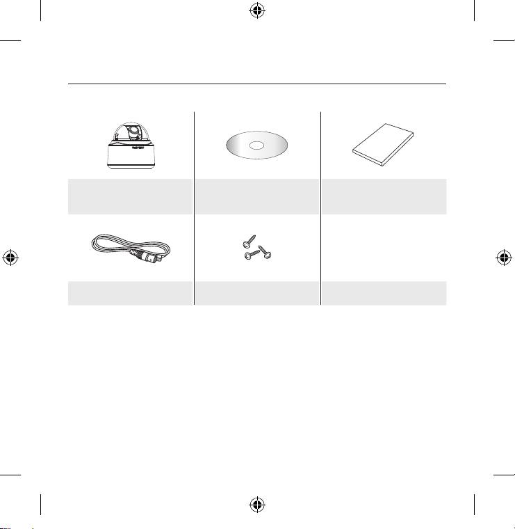
WHAT’S INCLUDED
Please check if your camera and accessories are all included in the product package.
User Manual/
Camera
User Manual
IP INSTALLER CD
Test Monitor Cable Screw
The Test Monitor Cable is connected to a portable displayer and used for testing the camera.
M
If you intend to use it for an actual monitoring camera, use the BNC cable instead.
SNC-B5368-ENG-QG.indd 2 2009-08-19 오후 8:41:59
English
3
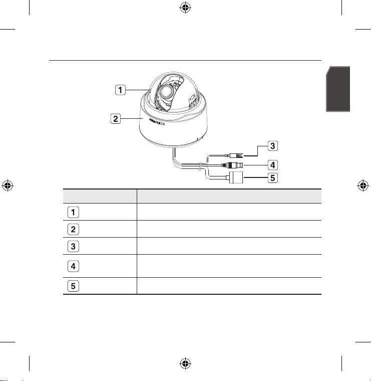
AT A GLANCE
Appearance
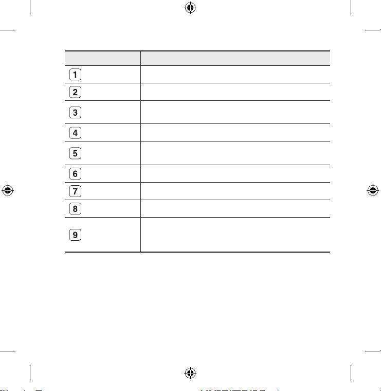
Item Description
Dome Cover Case cover used to protect the lens and the main unit.
Main Unit
Consists of: lens, switch board, PCB and screws.
Power Port
Used to plug in the power cable.
Used to connect the Video In connector of the monitor, from which the video
Video Output Port
signal of the camera outputs.
Network Port Used to connect the PoE or LAN cable.
Wipe out a dirty surface of the lens softly with a lens tissue or cloth to which you have applied
M
ethanol.
SNC-B5368-ENG-QG.indd 3 2009-08-19 오후 8:41:59
4
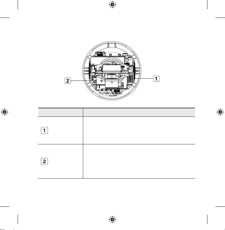
Inside
Item Description
Consists of two different ports:
- ALARM IN : Used to receive the alarm input signal.
Alarm I/O Port
- ALARM OUT : Used to output the alarm output signal.
- GND : Used for earth-grounding.
Restores all camera settings to the factory default. Press and hold it for about 3
seconds to turn off the system indicator and restart the system.
Reset Button
J
After resetting the camera, you must run the IP Installer program to change
the basic network settings such as IP address, Subnet mask, Gateway, etc.,
before you can connect to the network.
SNC-B5368-ENG-QG.indd 4 2009-08-19 오후 8:42:00
English
5
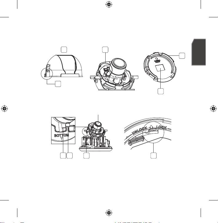
Components
1
3
4
2
5
Lens
6 7 8 9
SNC-B5368-ENG-QG.indd 5 2009-08-19 오후 8:42:08
6
Item Description
Inner Cover Cover used to protect the main unit.
Wing-Side Hook Tap on either end to remove the inner cover.
The Test Monitor Cable is connected to a portable displayer and used for testing
Monitor Out
the camera.
Bracket Used to install the camera on the wall or ceiling with the screws.
Remove this for wiring purposes if you intend to install the camera on the
Upper Lid
ceiling.
Zoom Lever Used to adjust or fix the zoom factor of the lens.
Focus Lever Turn it to the left or right to adjust the focus; turn it clockwise to fix the focus.
Tilt Screw Used to adjust or fix the tilt of the lens.
If you want to remove the bracket from the main unit or remove the camera
Release Lock
from the bracket, push this out and turn the main unit in the <UNLOCK>
direction.
SNC-B5368-ENG-QG.indd 6 2009-08-19 오후 8:42:17
English
7
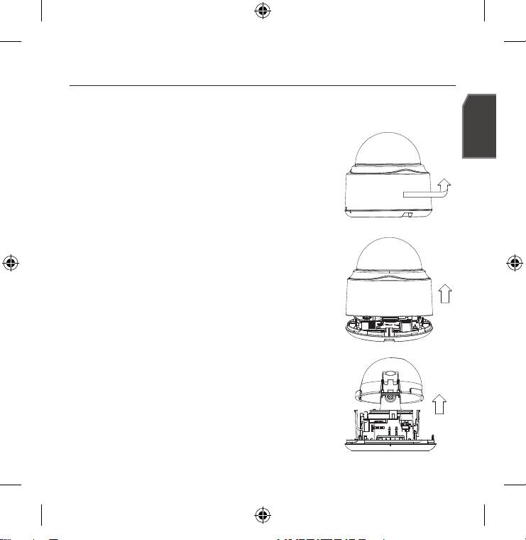
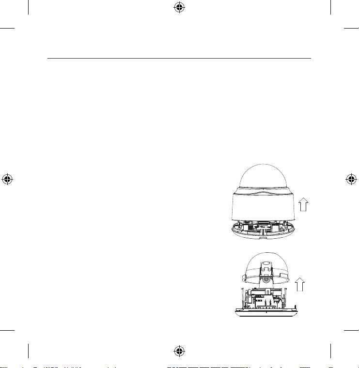
REMOVING THE COVERS
If you want to connect the Alarm I/O connectors, you must remove the dome cover and lens cover
beforehand.
1.
Turn the dome cover counter-clockwise.
2.
Remove the dome cover by lifting it up.
3.
Tap on either end of the lens cover to remove it.
SNC-B5368-ENG-QG.indd 7 2009-08-19 오후 8:42:19
8
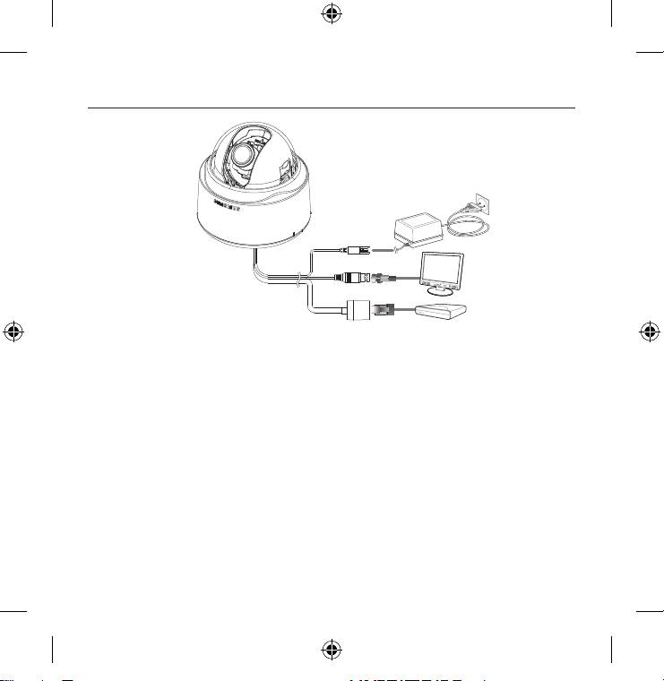
CONNECTING WITH OTHER DEVICE
Power
Monitor
Network
Power Supply
Connect the power adaptor to the power input port.
Be careful not to reverse the polarity when you connect the power cable.
J
You can also use a router featuring PoE (Power over Ethernet) to supply power to the camera.
Connecting to the monitor
Connect the [V_OUT] port of the camera to the video input port of the monitor.
Network Connection
Connect the Network cable to the local network or to the Internet.
SNC-B5368-ENG-QG.indd 8 2009-08-19 오후 8:42:20
English
9
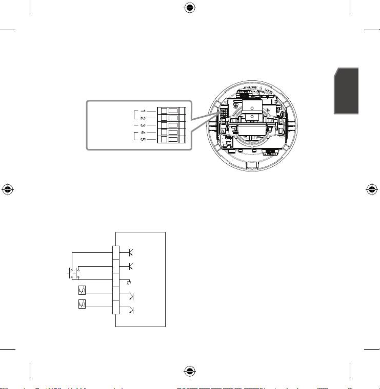
Connecting to the I/O port box
Connect the Alarm I/O cable to the corresponding port of the inner port box.
ALARM IN 1, 2 : Used to connect the alarm input signal.
GND : Used for earth-grounding.
ALARM OUT 1, 2 : Used to connect the alarm output signal.
Alarm I/O Wiring Diagram
ALARM IN 1
1
ALARM IN 2
2
GND
3
External Relay
ALARM OUT 1
4
External Relay
ALARM OUT 2
5
ALARM IN
GND
ALARM OUT
SNC-B5368-ENG-QG.indd 9 2009-08-19 오후 8:42:21
10
INSTALLATION
Precautions before installation
Ensure you read out the following instructions before installing the camera:
Select an installation site (ceiling or wall) that can endure at least 5 times of the camera
weight.
Stuck-in or peeled-off cables can cause damage to the product or a fire.
For safety purposes, keep anyone else away from the installation site. And put aside per-
sonal belongings from the site, just in case.
Installing the camera
1.
Hold down the bottom lock lever while removing the
cover with the other hand.
Removing the cover reveals the main unit and inner
cover.
2.
To fix the camera position, hold down either hook of
the inner cover and lift it up.
SNC-B5368-ENG-QG.indd 10 2009-08-19 오후 8:42:23
English
11
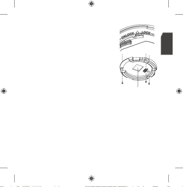
3.
Push the release lock out while turning the main unit in the
<UNLOCK> direction to remove the bracket.
If this doesn't work, use the hole on the bottom of the
bracket to turn the bracket in the <LOCK> direction.
4.
Use the provided screws (x3) to fix the bracket to a
desired position (ceiling or wall).
Ensure that the <CAMERA FRONT> label on the bracket faces the
direction for camera monitoring.
5.
Arrange the cables through the bracket to the ceiling or
wall.
Press hard the upper lid down to remove it before you can
arrange the cables through to the ceiling.
Upper Lid
If you do not intend to install the camera on the ceiling, use
the opposite empty area to the <CAMERA FRONT> label side for the wiring.
6.
Mount the main unit onto the bracket.
Align the marking hole of the main unit with the <CAMERA FRONT> label of the bracket,
and turn the unit in the <LOCK> direction.
7.
Adjust the lens in a desired direction.
For adjusting the lens direction, refer to "Adjusting the monitoring direction for the
camera".
8.
Secure the inner cover to the main unit.
Fit the two holes of the wing-side locks on the inner cover into the corresponding hole
of the main unit, and press it down until you hear a click.
9.
Fix the cover to the main unit.
Fit the protruding part inside the cover into the corresponding hole of the main unit, and
turn the cover to fix it.
SNC-B5368-ENG-QG.indd 11 2009-08-19 오후 8:42:32
12
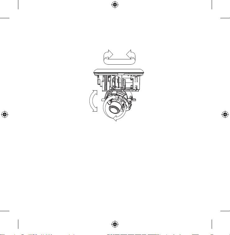
Adjusting the monitoring direction for the camera
Panning
Tilting
Lens rotation
You can adjust the camera direction only when the camera is fixed on the ceiling.
Then, turning the camera to the left or right is referred to as "Panning", while tilting the angle
is "Tilting". For panning, the panning limit is 220˚ for the clockwise, and 120˚ for the counter-
clockwise, a total of 340˚ enabled; further rotation is stopped by the stopper.
SNC-B5368-ENG-QG.indd 12 2009-08-19 오후 8:42:40
English
13
STATIC IP SETUP
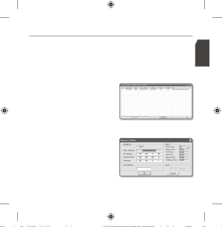
Manual Network Setup
Run <IP Installer.exe> to display the camera search list.
At the initial startup, both [Auto Set] and [Manual Set] will be grayed out.
For cameras found with the IPv6 setting, these buttons will be grayed out as the cameras do not
M
support this function.
1.
Select a camera in the search list.
Find the MAC (Ethernet) address labeled on
the rear of the camera.
Both the [Auto Set] and [Manual Set]
buttons will be activated.
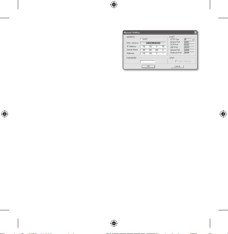
2.
Click [Manual Set].
The MANUAL SET dialog appears.
The default values of <IP Address>,
<Subnet Mask>, <Gateway>, and <HTTP Port> of the camera will be displayed.
The default <PASSWORD> is 4321.
3.
In the <ADDRESS> pane, provide the
necessary information.
MAC (Ethernet) Address : The MAC
(Ethernet) address of the applicable
camera will be set automatically so you
don't need to input it manually.
SNC-B5368-ENG-QG.indd 13 2009-08-19 오후 8:42:41
14
4.
In the <PORT> pane, provide necessary
information.
HTTP Port : Used to access the camera
using the Internet browser, defaulted to
80. Use the spin button to change the
HTTP Port value. The start value of the
port is 80, and increases or decreases
by 6 like 10000, 10006, 10012.
Device Port : Used to control the video signal transfer, defaulted to 60001(TCP).
TCP Port : Video signal transfer port using TCP protocols, defaulted to 60002(TCP).
UDP Port : Video signal transfer port using the UDP Unicast method, defaulted to
60003(UDP).
Upload Port : Used to upgrade the software fi rmware, defaulted to 60004(TCP).
Multicast Port : Video signal transfer port using the UDP Multicast method, defaulted
to 60005(UDP).
5.
Enter the password.
This is the login password for the "root" user who accesses the camera.
The default password is "4321".
6.
Click [OK].
Manual network setup will be completed.
7.
When the manual setup including <IP> is completed, the camera will restart.
SNC-B5368-ENG-QG.indd 14 2009-08-19 오후 8:42:42
English
15
Auto Network Setup
Run <IP Installer.exe> to display the camera search list.
At the initial startup, both [Auto Set] and [Manual Set] will be grayed out.
For cameras found with the IPv6 setting, these buttons will be grayed out as the cameras do not
M
support this function.
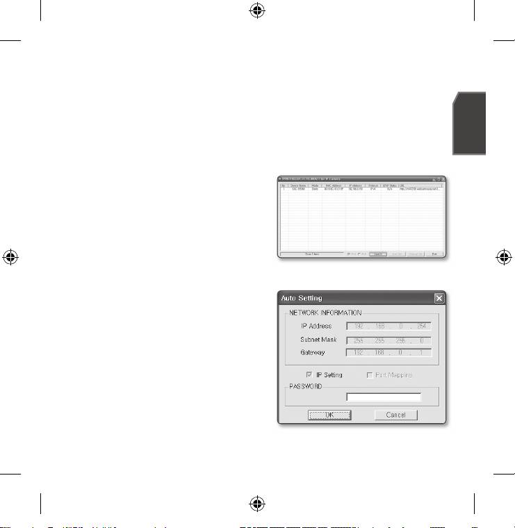
1.
Select a camera in the search list.
Find the MAC (Ethernet) address labeled on
the rear of the camera.
Both the [Auto Set] and [Manual Set]
buttons will be activated.
2.
Click [Auto Set].
The AUTO SET dialog appears.
The <IP Address>, <Subnet Mask>, and
<Gateway> will be set automatically.
3.
Enter the password.
This is the login password for the "root"
user who accesses the camera.
The default password is "4321".
4.
Click [OK].
Auto network setup will be completed.
5.
The camera will automatically complete
the network setting and restart.
SNC-B5368-ENG-QG.indd 15 2009-08-19 오후 8:42:42
16
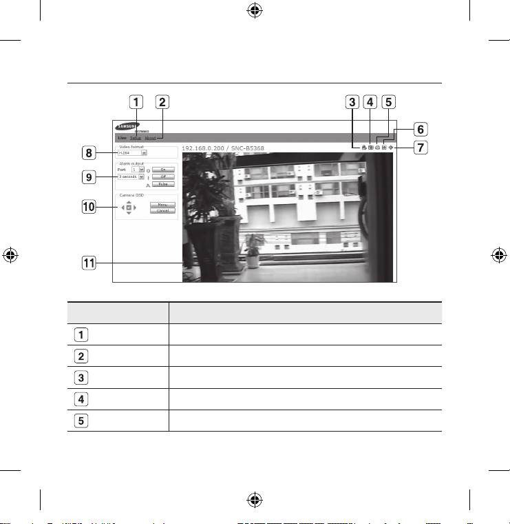
USING THE LIVE SCREEN
Item Description
Setup Move to the Setup screen.
About You can check the firmware version, serial number and manufacturer information.
Reset Alarm
Resets the Alarm icon. (the Alarm and Motion icons disappear.)
Capture Saves the snapshot as an image file in the .jpeg or .bmp format.
Print Prints out the current image.
SNC-B5368-ENG-QG.indd 16 2009-08-19 오후 8:42:42
English
17
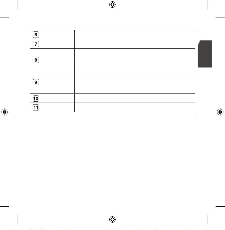
Record Saves the snapshot as a video file in the .avi format.
Full Screen Displays the Live screen in full screen.
You can set the video format(MJPEG, H.264/MPEG4)for vidoe files.
Video format
The context menu will differ, depending on the codec specified in <Select H.264 &
MPEG4 Video> of the active viewer.
On : Activates the specified Alarm Out port.
Alarm output
Off : Deactivates the specified Alarm Out port.
Pulse : Activates the Alarm Out port as much time as specified before deactivating it.
Camera OSD
Used to retrieve and customize the Camera Setup menu.
Viewer Screen Displays the Live video on the screen.
SNC-B5368-ENG-QG.indd 17 2009-08-19 오후 8:42:43
Correct Disposal of This Product
(Waste Electrical & Electronic Equipment)
(Applicable in the European Union and other European countries with separate collection systems)
This marking on the product, accessories or literature indicates that the product and its electronic accessories (e.g. charger,
headset, USB cable) should not be disposed of with other household waste at the end of their working life. To prevent
possible harm to the environment or human health from uncontrolled waste disposal, please separate these items from other
types of waste and recycle them responsibly to promote the sustainable reuse of material resources.
Household users should contact either the retailer where they purchased this product, or their local government office, for
details of where and how they can take these items for environmentally safe recycling.
Business users should contact their supplier and check the terms and conditions of the purchase contract. This product and
its electronic accessories should not be mixed with other commercial wastes for disposal.
SNC-B5368-ENG-QG.indd 18 2009-08-19 오후 8:42:43
