Samsung SCC-101BP: инструкция
Раздел: Бытовая, кухонная техника, электроника и оборудование
Тип: Цифровая Видеокамера
Инструкция к Цифровой Видеокамере Samsung SCC-101BP
SCC
-
130B/131B
SCC
-
130BP/131BP
SCC
-
100BP/101BP
User Guide
E
F
G
ES
I
RU
J
Part No.: AB68-00476A(01)
Printed in Korea
User Guide
User Guide
1. Read all of these instructions.
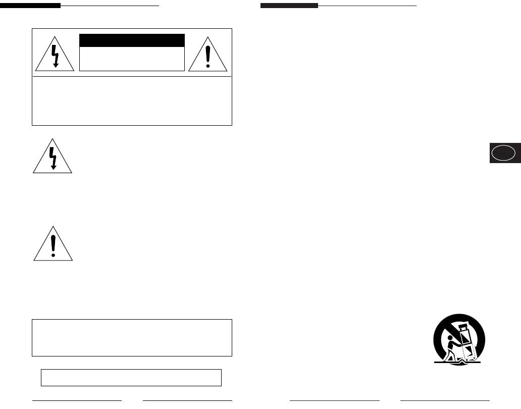
CAUTION
2. Save these instruction for later use.
RISK OF ELECTRIC
SHOCK, DO NOT OPEN
3. Unplug this appliance system from the wall outlet
before cleaning
CAUTION : TO REDUCE THE RISK OF ELECTRIC SHOCK, DO
Do not use liquid cleaners or aerosol cleaner.
NOT REMOVE COVER (OR BACK).
Use a damp cloth for cleaning.
NO USER-SERVICEABLE PARTS INSIDE.
REFER SERVICING TO QUALIFIED SERVICE
4. Do not use attachments not recommended by the
PERSONNEL.
appliance manufacturer, as they may cause
E
hazards.
The lightning flash, with an arrowhead
symbol, within an equilateral triangle, is
5. Do not use this appliance near water for example,
intended to alert the user to the presence of
near a bathtub, washbowl, kitchen sink, laundry
uninsulated “dangerous voltage” within the
tub, in a wet basement, or near a swimming pool,
product’s enclosure, that may be of
etc.
sufficient magnitude to constitute a risk of
6. Do not place this appliance on an unstable cart,
electric shock to persons.
stand, or table.
The exclamation point within an equilateral
The appliance may fall causing serious injury to a
triangle is intended to alert the user to the
child or adult, and serious damage to the
presence of important operating and
appliance.
maintenance (servicing) instruction in the
Use only with a cart or stand recommended by
literature accompanying the appliance.
the manufacturer’s instructions, and use a
mounting kit approved by the manufacturer.
An appliance and cart combination should be
moved with care. Quick stops, excessive force,
WARNING : TO PREVENT FIRE OR SHOCK HAZARD, DO
NOT EXPOSE THIS APPLIANCE TO RAIN OR
and uneven surfaces may
MOISTURE.
cause the appliance and cart
combination to overturn.
IMPORTANT SAFEGUARDS
ii
iii

User Guide
User Guide
7. Slots and openings in the cabinet on the back or
13. Unplug this appliance from the wall outlet
bottom are provided for ventilation, to insure
and refer servicing to qualified service
reliable operation of the appliance, and to protect
personnel under the following conditions:
from overheating.
a. When the power cord or plug is damaged or frayed.
These openings should never be blocked by
b. If liquid has been spilled into the appliance.
placing the appliance on a bed, sofa, rug or other
c. If the appliance does not operate normally by
similar surfaces. This appliance should never be
following the operating instructions. Adjust only those
placed near or over a radiator or heat register.
controls that are covered by the operating
E
This appliance should not be place in a built-in
instructions, as improper adjustment of other controls
installation such as a bookcase, unless proper
may result in damage and will often require extensive
ventilation is provided.
work by a qualified technician to restore the appliance
to normal operation.
8. This appliance should be operated only from the
d. If the appliance has been exposed to rain or water.
type of power source indicated on the marking
e. If the appliance has been dropped or the cabinet has
label. If you are not sure of the type of power
been damaged.
supplied to your home, consult your dealer or
f. When the appliance exhibits a distinct change in
local power company.
performance this indicates a need for service.
9. Do not allow anything to rest on the power cord.
Do not locate this appliance where the cord will
14. When replacement parts are required, be
be abused by people walking on it.
sure the service technician has used
replacement parts specified by the
10. Do not overload wall outlets and extension cords,
manufacturer that have the same
as this can result in fire or electric shock.
characteristics as the original part.
11. Follow all warnings and instructions marked on
Unauthorized substitutions may result in fire,
the appliance.
electric shock, or other hazards.
12. Do not attempt to service this appliance yourself,
15. Upon completion of any service or repairs to
as opening or removing covers may expose you
the appliance, ask the service technician to
to dangerous voltage or other hazards. Refer all
perform routine safety checks to determine
servicing to qualified service personnel.
that the appliance is in safe operating
condition.
iv
v

User Guide
User Guide
Contents
1. Introduction
........................................................
1. Introduction
3
Adopting the latest Super -HAD CCD,these cameras
provide the best monitoring function when they are
..............................................................
2. Features
4
connected to CCTV system.
..........................................................
3. Installation
5
....................
❈ In the mechanical fluorescent light environment, if you
E
Precautions in Installation and Use
5
attach MANUAL IRIS and turn the ELC switch among
.....................
Connecting Auto Iris Lens Connector
6
FUNCTION switches on, color may be rolled.
.....................................................
Mounting Lens
7
............................
Setting Lens Selection Switch
8
In this case, supply AC power before you turn L/L
.........................................
Adjusting Back Focus
9
switch among FUNCTION switches on.
................................................
Connecting Cable
11
(NTSC:60HZ , PAL:50HZ)
.......................
4. Names and Functions of Parts
14
☞
COLOR ROLLING is the problem that color on the
...........................
Names and Functions of Parts
14
monitor screen changes non-periodically.
................................................
Function Switches
16
This happens when White Balance is not fixed,
because a mechanical fluorescent light flickers
.......................................
when it’s cycle is the same to the cycle of the power
5. Product Specification
21
frequency.
2
3

User Guide
User Guide
2. Features
3. Installation
High Sensitivity
Precautions in Installation and Use
Adopting the 1/3" Super HAD CCD that has the latest built-
in microchip lens, the high sensitivity is realized.
Do not attempt to disassemble the camera yourself.
Excellent Back Light Compensation
Be cautious in handling the camera. Avoid striking or
Even when an intense light source or sunlight is in the back
shaking the camera. Be cautious to avoid damage on
E
of your subject, a clear image will be provided due to the
the camera caused by improper storage or operation.
ideal combination of the excellent performance of the high
light compression (KNEE Compensation) function and the
Do not expose this camera to rain or moisture. Do not
BLC (Back Light Compensation) function.
operate this camera on a wet place.
Digital Line-lock
The control and reliability have been enhanced due to the
Do not use strong or abrasive detergents when
Full Digital Line Lock, which allows users to adjust the Line
cleaning the camera body.
Sync Phase.
Use a dry cloth to clean the camera.
Resolution
Keep the camera at a cool place away from the direct
High resolution is realized due to the Full Digital Image
sunlight. Leaving it under the direct sunlight may result
Processing by the DSP for monitoring camera.
in the malfunction of the unit.
4
5
User Guide
User Guide
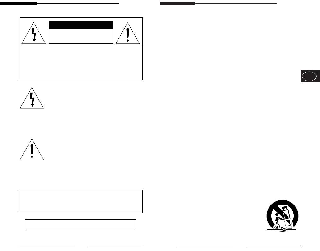
Connecting Auto Iris Lens Connector
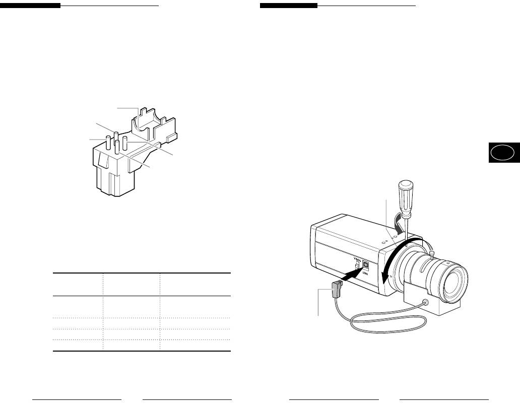
Mounting the Lens
Prepare the following Auto Iris Lens Connector supplied
Loosen a screw fixing the Flange Back Adjustment Ring by
with the camera.
turning it counterclockwise and turn the Adjustment Ring to
the "C" direction (counterclockwise) until it stops. Failure to
Rib
do so may result in a damage caused by the bump of the lens
against the image sensor part in the camera when mounting
Pin3
the lens.
Pin1
E
Pin4
Pin2
C Direction
Connect the cable of the control cable, whose covering is
stripped, to the Auto Iris Lens Connector as shown below.
Pin Number DC Control Type Video Control Type
1 Damp(-) Power Source (+9V)
2 Damp(+) Not used
3 Drive(+) Video Signal
4 Drive(-) GND
Auto Iris Control Cable
6
7
User Guide
User Guide
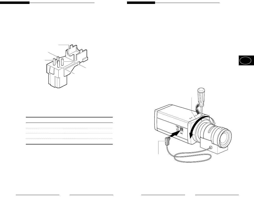
Setting Lens Selection Switch
Adjusting Back Focus
When lens mounting is completed, set the Lens selection
Although the Back Focus of the camera has been adjusted
Switch on the side of the camera according to the mounted
in the factory before its shipment, the focus may not be
lens type.
accurate for a certain type of the lens. In this case, follow
the procedures below to adjust the Back Focus. First,
When the mounted lens is an Auto Iris Lens of the DC
following is how to adjust the Back Focus of the Fixed
control type, set the Lens Selection Switch to "DC".
Focus Lens.
When the mounted lens is an Auto Iris Lens of the Video
E
control type, set the Lens Selection Switch to "VIDEO".
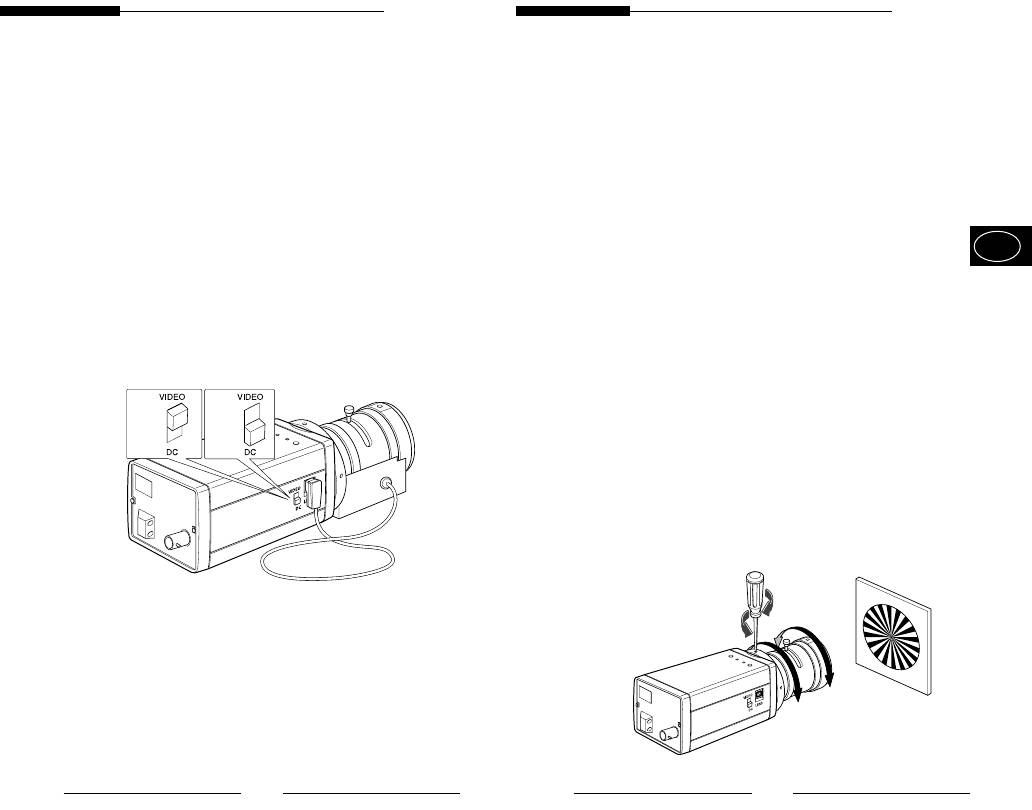
Lightly loosen the screw fixing the Back Focus
Adjustment Ring using a screwdriver.
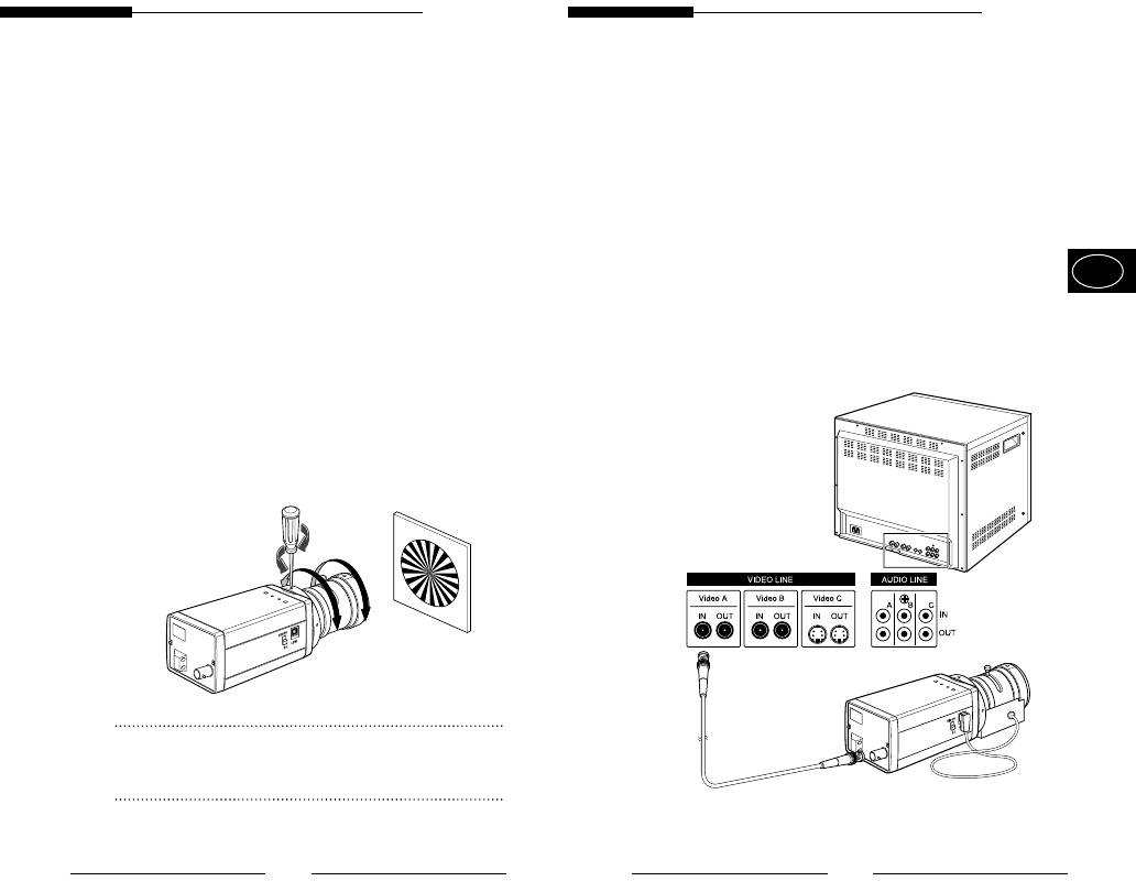
Image a vivid subject (with check patterns) at a distance
of more than 10m away and turn the Focus Ring to the
infinity () position.
Adjust the Back Focus Adjustment Ring to obtain the
clearest image of the subject.
Fasten the screw fixing the Back Focus Adjustment
Ring.
8
9
User Guide
User Guide
The following describes how to adjust the Back Focus when
Connecting Cable
using a Zoom lens.
Lightly loosen the screw fixing the Back Focus
After mounting the lens and setting the Lens Selection
Adjustment Ring using a screwdriver.
Switch, connect the prepared cable to each terminal of the
camera.
Image a vivid subject (with check patterns) at a distance
of 3~5m away and adjust the zoom of the lens to TELE
First, connect one end of the BNC cable to the Video
as far as it goes. Then adjust the Focus Ring of the
Output Terminal (VIDEO OUT) of the camera.
lens to obtain the clearest image of the subject.
E
Adjust the zoom of the lens to WIDE as far as it goes.
Then connect the other end of the BNC cable to the
Then turn the Back Focus Ring of the camera to obtain
Video Input Terminal of the monitor.
the clearest image of the subject.
Repeat no. & 2~3 times to exactly coincide the
zoom focus from TELE and with that from WIDE.
Fasten the screw fixing the Back Focus Adjustment
Ring.
Video In Terminal on the rear of the monitor
Note:
BNC Cable
Turning the Back Focus Adjustment Ring to the "C" direction
beyond the adjustable range makes a sound at the limit.
Video Out Terminal
(VIDEO OUT)
10
11
User Guide
User Guide
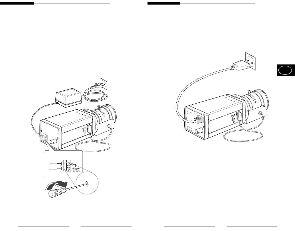
AC24V/DC12V Power Input Camera.
AC230V Power Input Camera
Connect 2 lines of the power adapter using a
Connect the power input cord to the AC 230V power
Phillips screwdriver to the Power IN Terminal of the
source.
camera as shown below.
Without the distinction of the polarity, connect to
the AC 24V or AC 12V power source.
E
12
13
User Guide
User Guide
Auto Iris Lens Connector
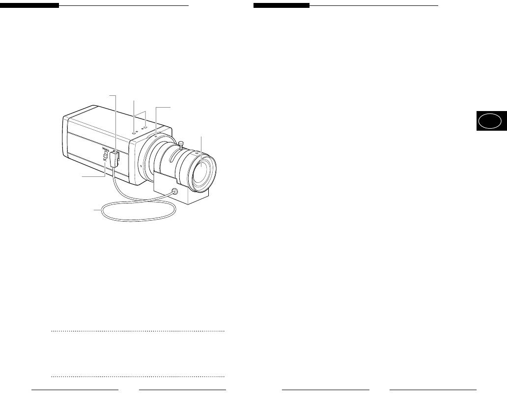
4. Names and Functions of Parts
Used for supplying power, which is required to control
Names and Functions of Parts
the iris of the lens, as well as control signal, video
signal, or DC signal to the Auto Iris Control Lens.
• Side View
Auto Iris Lens Control Cable
# Auto lris Lens Connector
! Groove for Mount Adapter
Used for transmitting the control signals to the camera
%
Flange-Back
to control the iris of the lens.
Adjustment Ring
E
@ Auto Iris Lens
Flange-Back Adjustment Ring
Used for adjusting the Back Focus.
ALC Lens Selection Switch
^ ALC Lens Selection
Used when selecting the type of Auto Iris Lens to use.
Switch
DC : Select this switch to DC when Iris Lens requiring
DC control signal is mounted.
$ Auto Iris Lens Control
Cable
VIDEO : Select this switch to VIDEO when Auto Iris
Lens requiring VIDEO control signal is
mounted.
Groove for Mount Adapter
Use this groove for fixing the mount adapter to be
connected to the bracket with screws to mount the
camera on the bracket.
Auto Iris Lens (Option)
Lens to be mounted on the camera
Note
When the surface of the camera lens is contaminated,
wipe the surface gently with a tissue for lens or a cotton
cloth applied with ethanol.
14
15
User Guide
User Guide
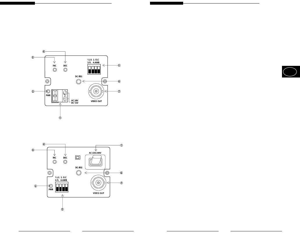
Power Connection Terminal
• Rear Panel
Terminal to be connected to the power (adapter) cable
Connect it to AC 24V or DC 12V.
AC24V/DC12V Power Input Camera
Power Indication LED
While the power is properly supplied to the camera, the
LED is turned on.
, INC/DEC Switch
E
The LINELOCK mode is useful for controlling Vertical
Synchronous Phase.
AC230V Power Input Camera
16
17
User Guide
User Guide
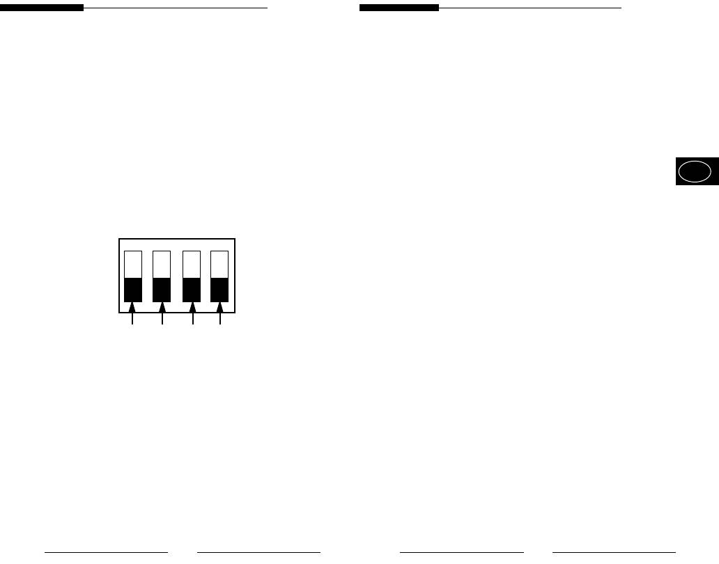
Function Switches
3) SW3 (FL):
1) SW1 (LL):
This is to prevent flicker on the screen when NTSC
When set to OFF, the camera operates in the Internal
system is used in 50HZ power supply region and PAL
Sync mode. When set to ON, it operates in the Power
system is used in 60HZ power supply region. That is to
Sync mode. If the camera is set to INT (Internal Sync)
prevent shaking on the screen resulted from the
when monitoring in the Auto Switching mode with more
discordance of the vertical sync frequency and the
than one camera connected to a sequential switcher, etc,
flicker frequency of the illumination. While this switch is
the jump of the screen will occur each time of screen
ON, the electronic shutter is fixed to 1/100sec (NTSC)
switching. To switch the screen gently without a jump, set
or 1/120 sec (PAL).
E
the camera to LL and adjust the Vertical Sync Phase using
4) SW4 (AWB ):
the INC/DEC switch.
When setting up ON, the color of screen is adjusted
1. L/L 2. ELC
automatically in accordance with the change of lighting
3. FL 4. AWB
color temperature by the change of outer environment.
ON
(ATW) If the lighting condition is steady, OFF setting is
available. The camera memorizes the lighting color
temperature at the time when the switch setting is
changed from ON to OFF, and the camera color is
adjusted to the memorized color temperature. (AWC)
SW1 SW2 SW3 SW4
If the lighting color temperature is changed and you
want to make the camera be memorized/operated with
2) SW2 (ELC):
the changed color temperature, re-operate the switch
Use this switch with the Manual Iris Lens. While this
On/Off operation. However, be aware that an error may
switch is ON, the speed of the electronic shutter varies
occur under the following conditions.
with the brightness of the subject from 1/60 to
First, a case that the subject is big, single color of the
1/120,000 sec for automatically controlling the
high chroma, and in the center of the screen or a
brightness of the screen. However, with the Auto Iris
case with almost no white color on the screen
Lens (DC or Video Control), be sure to switch OFF.
Second, a case with a specific illumination such as a
Color Rolling may occur in this mode.
natrium lamp
In that case, input AC power source to the camera and
select SW1 “ON”.
To adjust the Vertical Sync Phase using the INC/DEC
(NTSC : 60HZ, PAL : 50HZ)
switch in LL mode, the SW4 must be set to AWB “ON”.
For DC 12V, the INT/LL mode is fixed to INT.
18
19

User Guide
User Guide
DC Iris Level Control
5. Product Specifications
When the ALC Lens Selection Switch is set to DC, adjust
this Iris Level Control using an adjustment rod such as a
SCC-130B/131B
screwdriver.
Video Output Terminal
Item Contents
This is a terminal to be connected to the Input Terminal
Product Type CCTV Camera
of the monitor. Through this terminal, the video signals
Broadcasting NTSC STANDARD SYSTEM
are outputted.
E
System
CCD 1/3” IT type S-HAD CCD
No. of Pixel 130B : 510(H) x 492(V)
131B : 768(H) x 494(V)
Scanning Type 525 Line, 2:1 Interlace
Frequency INTERNAL : 15,734 HZ(H)
59,94 HZ(V)
LINE LOCK :15,750 HZ(H)
60 HZ(V)
Sync Type INTERNAL
LINE LOCK
(When AC24V power source is used)
Resolution 130B : 330TV Lines
131B: 520TV Lines
S/N Ratio 50dB (AGC OFF)
Min. Object 130B : 0.15 Lux (F1.2)
Illumination 131B : 0.3 Lux (F1.2)
20
21

User Guide
User Guide
SCC-100BP/101BP/130BP/131BP
ALC /ELC ALC
DC IRIS LENS
Item Contents
VIDEO LENS
Product Type CCTV Camera
ELC
Broadcasting PAL STANDARD SYSTEM
Electronic SHUTTER IRIS function
E
System
1/60 to 1/120,000 sec
CCD 1/3” IT type S-HAD CCD
Color Temperature ATW/AWC Mode
No. of Pixel 100BP/130BP : 500(H) x 582(V)
BLC ON(Back Light Compensation)
101BP/131BP : 752(H) x 582(V)
AGC ON
Scanning Type 625 Line, 2:1 Interlace
Video Output COMPOSITE VIDEO OUT
Frequency INTERNAL : 15,625 HZ(H)
1V p_p 75 /BNC
50 HZ(V)
Power Source AC24V10%(60Hz0.3Hz)
LINE LOCK :15,625 HZ(H)
DC12V -5% ~ +10%
50 HZ(V)
Power Consumption About 3 Watts
Sync Type INTERNAL
Operating
-10~+50
LINE LOCK
(When AC power source is used)
Temperature
Resolution 100BP/130BP : 330TV Lines
Operating
~90%
131BP/101BP: 520TV Lines
Humidity
S/N Ratio 50dB (AGC OFF)
Size 65(W) x 52(H) x 133(L)mm
Min. Object 100BP/130BP : 0.15 Lux (F1.2)
(BNC included)
Illumination 131BP/101BP : 0.3 Lux (F1.2)
Weight 450g
22
23

User Guide
User Guide
ALC /ELC ALC
DC IRIS LENS
VIDEO LENS
ELC
Electronic SHUTTER IRIS function
1/60 to 1/120,000 sec
Color Temperature ATW/AWC Mode
E
BLC ON(Back Light Compensation)
AGC ON
Video Output COMPOSITE VIDEO OUT
1V p_p 75 /BNC
Power Source 100BP/101BP
AC220V~240V(50Hz0.3Hz)
130BP/131BP
AC24V10%(50Hz0.3Hz)
DC12V -5% ~ +10%
Power Consumption 100BP/101BP: About 4 Watts
130BP/131BP: About 3 Watts
Operating
-10~+50
Temperature
Operating
~90%
Humidity
Size 65(W) x 52(H) x 133(L)mm
(BNC included)
Weight 100BP/101BP : About 550g
130BP/131BP : About 450g
24
Manuel de l’utilisateur
Manuel de l’utilisateur
1. Lisez l’ensemble de ces instructions.
AVERTISSEMENT
2. Conservez ces instructions en vue d’une future
RISQUE DE CHOC ELECTRIQUE,
utilisation.
NE PAS OUVRIR
3. Débranchez cet appareil de la prise de courant
AVERTISSEMENT : AFIN DE RÉDUIRE LE RISQUE DE CHOC
murale avant de le nettoyer.
ELECTRIQUE, NE RETIREZ PAS LE COUVERCLE
N’utilisez pas de nettoyant liquide ou en aérosol.
(OU L’ARRIÈRE). AUCUNE PIÈCE RÉPARABLE
PAR L’UTILISATEUR À L’INTÉRIEUR. CONFIEZ LA
Utilisez un chiffon humide pour le nettoyage.
RÉPARATION À UN PERSONNEL QUALIFIÉ.
4. N’utilisez pas de fixations qui ne sont pas
recommandées par le fabriquant, celles-ci
L’éclair accompagné d’un symbole en forme
pourraient provoquer des risques.
de pointe de flèche dans un triangle
F
équilatéral, sert à prévenir l’utilisateur qu’il y
5. N’utilisez pas cet appareil à proximité d’eau par
a des “tensions dangereuses” non isolées à
exemple, d’une baignoire, d’un lavabo, d’un évier
l’intérieur de l’appareil, qui peuvent être
de cuisine, d’un bac à laver, dans un sous-sol
suffisamment élevées pour représenter un
mouillé, à proximité d’une piscine, etc.
risque de choc électrique.
6. Ne disposez pas cet appareil sur un chariot, plan
ou table instable.
Le point d’exclamation à l’intérieur d’un
L’appareil risque de tomber et provoquer de
triangle équilatéral sert à alerter l’utilisateur
sérieuses blessures à un enfant ou un adulte, et
de la présence d’importantes instructions
pourrait être endommagé.
relatives au fonctionnement et à la
N’utilisez qu’avec un chariot ou plan recommandé
maintenance (réparation) dans la
par le fabriquant et utilisez un kit de montage
documentation qui accompagne l’appareil.
agréé par le fabriquant.
Un ensemble appareil et chariot doit être déplacé
avec précaution. Les arrêts
rapides, une force excessive
ATTENTION: Afin de prevenir des chocs electriques,
ainsi que des surfaces
ne pas exposer l'appareil à l'hulidité ou a
irrégulières risque de provoquer
la pluie.
un renversement de l’appareil et
du chariot.
REMARQUE IMPORTANTE
ii
iii

Manuel de l’utilisateur
Manuel de l’utilisateur
7. Les emplacements et les ouvertures à l’arrière et
13. Débranchez l’appareil de la prise murale et
au bas de l’armoire sont prévus pour la ventilation,
adressez-vous à un personnel qualifié pour les
afin d’assurer un fonctionnement fiable de
réparations dans les cas suivants :
l’appareil et d’éviter la surchauffe.
a. Lorsque le cordon d’alimentation ou la prise est
Ces ouvertures ne doivent jamais être bloquées,
endommagé ou effiloché.
en plaçant l’appareil sur un lit, un canapé, un tapis
b. Si du liquide a pénétré dans l’appareil.
ou d’autres surfaces identiques. Il convient de ne
c. Si l’appareil ne fonctionne pas normalement en
jamais placer cet appareil à proximité ou sur un
suivant les instructions relatives au fonctionnement.
Ne réglez que les commandes dont il est question
radiateur ou un générateur de chaleur.
dans les instructions relatives au fonctionnement. Un
Cet appareil ne doit pas être placé dans une
mauvais réglage d’autres commandes risquerait de
installation intégrée comme par exemple une
provoquer des dommages et demanderait un travail
bibliothèque, à moins qu’il n’y ait une ventilation
F
important de la part d’un technicien pour obtenir un
adaptée.
fonctionnement normal.
8. Il convient de ne faire fonctionner cet appareil qu’à
d. Si l’appareil a été exposé à la pluie ou à l’eau.
partir du type de source d’alimentation indiqué sur
e. Si l’appareil est tombé ou si l’armoire a été
endommagée.
l’étiquette. Si vous n’êtes pas sûr du type
f. Lorsque l’appareil présente un net changement au
d’alimentation de votre maison, consultez votre
niveau de ses performances cela indique qu’il
revendeur ou l’entreprise d’électricité locale.
convient de le faire réparer.
9. Ne laissez rien sur le cordon d’alimentation. Ne
14. Lorsqu’il est nécessaire de changer des pièces,
placez pas cet appareil dans un endroit où le
assurez-vous que le technicien a utilisé des
cordon risque d’être piétiné.
pièces de rechange recommandées par le
10. Ne surchargez pas les prises de courant murales
fabriquant qui présentent les mêmes
et les rallonges électriques, cela pourrait
caractéristiques que la pièce d’origine.
occasionner un incendie ou un choc électrique.
Des remplacements non autorisés peuvent
11. Suivez tous les avertissements et toutes les
provoquer un incendie, un choc électrique, ou
instructions spécifiés sur l’appareil.
d’autres dangers.
12. Ne tentez pas de réparer cet appareil vous-
15. Après un dépannage ou une réparation de
même. L’ouverture ou le retrait des couvercles
l’appareil, demandez au technicien d’effectuer les
peut vous exposer à des tensions dangereuses
vérifications de sécurité courantes afin d’établir
ou d’autres risques. Faites appel à un personnel
que l’appareil est en bon état de fonctionnement.
qualifié pour toute opération de réparation.
iv
v
Manuel de l’utilisateur
Manuel de l’utilisateur
Contenu
1. Introduction
..............................................................
1. Introduction
3
Avec un Super -HAD CCD tout récent, ces caméras
......................................................
offrent les meilleures fonctions de surveillance en
2. Caractéristiques
4
connexion avec le système CCTV.
................................................................
3. Installation
5
.............
Précautions d’installation et d’utilisation
5
❈ Si vous installez un diaphragme manuel et activez le
Branchement du connecteur de l’objectif du
bouton de fonction ELC dans un environnement
..........................................
diaphragme automatique
6
avec un éclairage fluorescent, la couleur risque de
................................................
F
Montage de l’objectif
7
tourner.
................
Paramétrage du sélecteur de l’objectif
8
.....................
Réglage de la mise au point arrière
9
Dans ce cas, sélectionnez l’alimentation CA avant
...............................................
Câble de connexion
11
d’activer bouton de fonction L/L.
(NTSC : 60 Hz, PAL : 50 Hz)
4. Noms et fonction des pièces
.................................. 14
...............................................................
Vue latérale
14
☞
L’ondulation de couleur est un phénomène de
......................................................
Panneau arrière
16
changement non périodique de la couleur sur l’écran
du moniteur.
5. Caractéristiques du produit .........................
21
Ceci arrive lorsque la Balance des Blancs n’est pas
fixée à cause d’une vacillation d’un éclairage
mécanique fluorescent et que son cycle est identique
à celui de la fréquence d’alimentation.
2
3

Manuel de l’utilisateur
Manuel de l’utilisateur
2. Caractéristiques
3. Installation
Sensibilité élevée
Précautions d’installation et d’utilisation
Grâce à l’appareil aérothermique CCD Super 1/3" et
son objectif micropuce intégré dernier cri, on obtient
➀ N’essayez pas de démonter la caméra
une sensibilité élevée.
vous-même.
Excellente compensation de contre-jour
➁ Soyez vigilant lors de la manipulation de la
Malgré la présence d’un éclairage intense ou d’un
caméra. Evitez de la cogner ou de la secouer.
rayonnement du soleil derrière le sujet, vous pouvez
Faites attention aux dommages qui pourraient
obtenir une image nette grâce à une combinaison
F
être occasionnés suite à un rangement ou un
idéale de l’excellente fonction de compression
fonctionnement inadapté.
d’éclairage intense (Compensation KNEE) et de la
fonction BLC (Back Light Compensation : Correction
➂ N’exposez pas cette caméra à la pluie ou à
du contre-jour)
l’humidité.
Verrouillage de la ligne numérique
Ne faites pas fonctionner cette caméra dans un
La commande ainsi que la fiabilité ont été
endroit mouillé.
améliorées grâce au verrouillage complet de la ligne
numérique, ce qui permet aux utilisateurs de régler
➃ N’utilisez aucun détergent fort ou abrasif lorsque
la phase de synchronisation de la ligne.
vous nettoyez le corps de la caméra.
Nettoyez-la à l’aide d’un chiffon sec.
Résolution
La haute résolution est réalisée grâce au processus
➄ Gardez la caméra dans un endroit frais à l’abri
d’image ‘Full Digital’ par le DSP à partir de la caméra de
du soleil. La laissez exposée au soleil peut
surveillance.
provoquer un mauvais fonctionnement de
l’appareil.
4
5
Manuel de l’utilisateur
Manuel de l’utilisateur
Branchement du connecteur de l’objectif
Montage de l’objectif
du diaphragme automatique
Desserrez la vis fixant la bague de réglage de la
Préparez le connecteur (indiqué ci-après) de
face d’appui en la tournant dans le sens inverse des
l’objectif du diaphragme automatique fourni avec la
aiguilles d’une montre et tournez la bague de
caméra.
réglage dans la direction "C" (sens inverse des
aiguilles d’une montre) jusqu’à ce qu’elle s’arrête.
Rib
Le non-respect de cette procédure peut causer un
Broche 3
dommage dû à un choc de l’objectif contre le
capteur d’image dans la caméra lors du montage
Broche 1
de l’objectif.
F
Broche 4
Broche 2
Direction de C
Branchez le câble du câble de contrôle, celui dont la
gaine est dénudée, au connecteur de l’objectif du
diaphragme automatique comme indiqué ci-après.
Numéro de Type de Type de
la broche commande DC commande vidéo
Source d’alimentation
1 Damp(-)
(+ 9 V)
Diaphragme
2 Damp(+) Non utilisé
automatique
3 Drive(+) Signal vidéo
Câble de
4 Drive(-) Terre
commande
6
7

