Samsung LE-40 B530 P7W: GENERAL INFORMATION
GENERAL INFORMATION: Samsung LE-40 B530 P7W
English - 2
GENERAL INFORMATION
N
Figures and illustrations in this User Manual are provided for reference only and may differ from actual product appearance.
Product design and specications may be changed without notice in order to enhance product performance.
¦
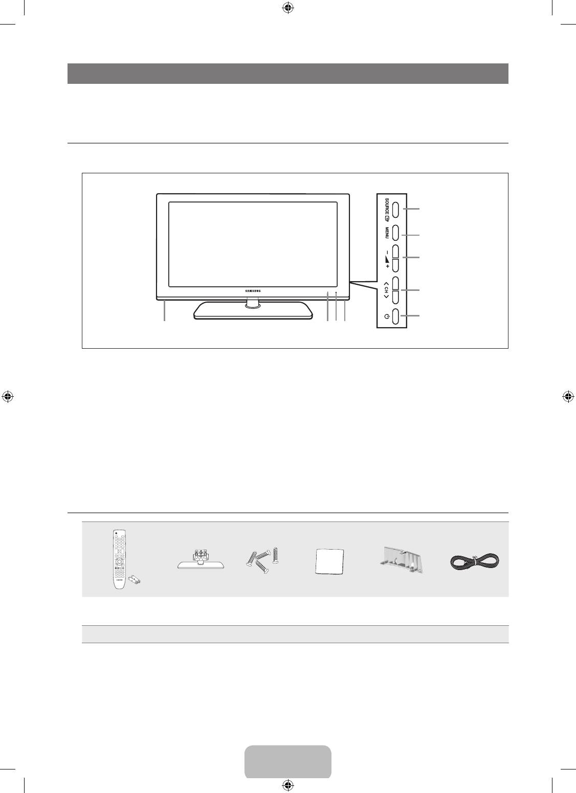
Viewing the Control Panel
N
The product colour and shape may vary depending on the model.
N
You can use a button by pressing the side panel buttons.
1
SOURCE
E
: Toggles between all the available input sources. In the on-screen menu, use this button as you would use the
ENTER
E
button on the remote control.
2
MENU: Press to see an on-screen menu of your TV’s features.
3
Y
: Press to increase or decrease the volume.
In the on-screen menu, use the
Y
buttons as you would use the ◄ and ► buttons on the remote control.
4
Z
: Press to change channels. In the on-screen menu, use the
Z
buttons as you would use the ▼ and ▲ buttons
on the remote control.
5
P
(POWER): Press to turn the TV on and off.
6
SPEAKERS
7
REMOTE CONTROL SENSOR: Aim the remote control towards this spot on the TV.
8
POWER INDICATOR: Blinks and turns off when the power is on and lights up in stand-by mode.
¦
Accessories
(M4 X L16)
Remote Control &
Batteries (AAA x 2)
Stand Stand Screw X 4 Cleaning Cloth Cover-Bottom Power Cord
●
Owner’s Instructions
●
Warranty card
●
Safety Guide
N
Please make sure the following items are included with your LCD TV. If any items are missing, contact your dealer.
N
Warranty card / Safety Guide (Not available in all locations)
N
The items colour and shape may vary depending on the model.
1
2
3
4
5
766 8
BN68-01893F-Eng.indd 2 2009-02-24 �� 2:57:18
English - 3
¦
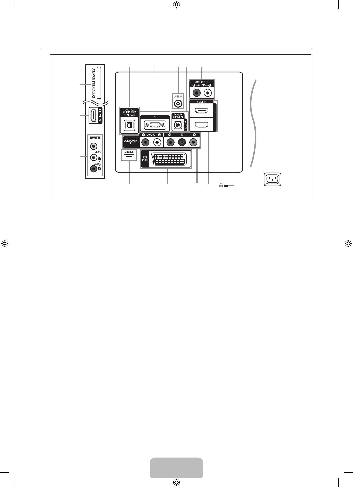
Viewing the Connection Panel
N
The product colour and shape may vary depending on the model.
N
Whenever you connect an external device to your TV, make sure that power on the unit is turned off.
N
When connecting an external device, match the colour of the connection terminal to the cable.
1
DIGITAL AUDIO OUT (OPTICAL)
–
Connects to a Digital Audio component such as a Home theatre receiver.
N
When the HDMI IN jacks are connected, the DIGITAL AUDIO OUT (OPTICAL) jack on the TV outputs 2 channel audio
only. If you want to hear 5.1 channel audio, connect the Optical jack on the DVD / Blu-ray player or Cable / Satellite Box
directly to an Amplier or Home Theatre, not the TV.
2
PC
–
Connect to the video output jack on your PC.
3
ANT IN
Connects to an antenna or cable TV system.
4
PC/DVI(HDMI 1)[AUDIO]
–
Connect to the audio output jack on your PC.
–
DVI audio outputs for external devices.
5
AUDIO OUT [R-AUDIO-L]
–
Connect RCA audio cables to AUDIO OUT [R-AUDIO-L] on the rear of your set and the other ends to corresponding
audio in connectors on the Amplier or DVD Home Theatre.
6
KENSINGTON LOCK (depending on the model)
–
The Kensington Lock (optional) is a device used to physically x the system when used in a public place. If you want to
use a locking device, contact the dealer where you purchased the TV.
N
The location of the Kensington Lock may be different depending on its model.
7
HDMI IN 1, HDMI IN 2, HDMI IN 3
–
Connects to the HDMI jack of a device with an HDMI output.
N
No sound connection is needed for an HDMI to HDMI connection.
N
Use the HDMI IN 1 jack for DVI connection to an external device. Use a DVI to HDMI cable or DVI-HDMI adapter (DVI to
HDMI) for video connection and the PC/DVI(HDMI 1)[AUDIO] jacks for audio.
N
You can also use the ports to connect to a PC.
N
What is HDMI?
‘High Denition Multimedia interface’ allows the transmission of high denition digital video data and multiple channels of
digital audio.
The HDMI / DVI terminal supports DVI connection to an extended device with the appropriate cable (not supplied).
The difference between HDMI and DVI is that the HDMI device is smaller in size, has the HDCP (High Bandwidth Digital
Copy Protection) coding feature installed, and supports multi - channel digital audio.
1 2 43 5
@
7
!
0 9 8 7 6
[TV Side Panel]
[TV Rear Panel]
Power Input
BN68-01893F-Eng.indd 3 2009-02-24 �� 2:57:19

English - 4
N
The TV may not output sound and pictures may be displayed with abnormal colour when DVD / Blu-ray player / Cable
Boxes / Satellite receivers supporting HDMI versions older than 1.3 are connected. When connecting an older HDMI
cable and there is no sound, connect the HDMI cable to the HDMI IN 1 jack and the audio cables to the PC/DVI(HDMI
1)[AUDIO] jacks on the back of the TV. If this happens, contact the company that provided the DVD / Blu-ray player /
Cable Box / Satellite receiver to conrm the HDMI version, then request a rmware update. HDMI cables that are not 1.3
may cause annoying icker or no screen display.
8
COMPONENT IN
–
Connect component video cables (optional) to component connector (PR, PB, Y) on the rear of your set and the other ends
to corresponding component video out connectors on the DTV or DVD.
–
If you wish to connect both the Set-Top Box and DTV (or DVD), you should connect the Set-Top Box to the DTV (or DVD)
and connect the DTV (or DVD) to component connector (PR, PB, Y) on your set.
–
The PR, PB and Y connectors on your component devices (DTV or DVD) are sometimes labelled Y, B-Y and R-Y or Y, Cb
and Cr.
–
Connect RCA audio cables (optional) to [R-AUDIO-L] on the rear of your set and the other ends to corresponding audio
out connectors on the DTV or DVD.
9
EXT
Connector
Input Output
Video Audio (L / R) RGB Video + Audio (L / R)
EXT O O O Only TV or DTV output is available.
–
Inputs or outputs for external devices, such as VCR, DVD, video game device or video disc players.
0
SERVICE
–
Connector for software upgrades.
!
AV IN [VIDEO] / [R-AUDIO-L]
–
Connect RCA cable to an appropriate external A/V device such as VCR, DVD or Camcorder.
–
Connect RCA audio cables to [R-AUDIO-L] on your set and the other ends to corresponding audio out connectors on the
A/V device.
@
COMMON INTERFACE Slot
–
When not inserting ‘CI CARD’ in some channels, ‘Scrambled Signal’ is displayed on the screen.
–
The pairing information containing a telephone number, CI CARD ID, Host ID and other information will be displayed in
about 2~3 minutes. If an error message is displayed, please contact your service provider.
–
When the channel information conguration has nished, the message ‘Updating Completed’ is displayed, indicating that
the channel list is now updated.
N
You must obtain a CI CARD from a local cable service provider. Remove the CI CARD by carefully pulling it out with your
hands since dropping the CI CARD may cause damage to it.
N
Insert the CI-Card in the direction marked on it.
N
The place of the COMMON INTERFACE Slot may be different depending on its model.
N
CAM is not supported in some countries and regions, check with your authorized dealer.
BN68-01893F-Eng.indd 4 2009-02-24 �� 2:57:19
English - 5
¦
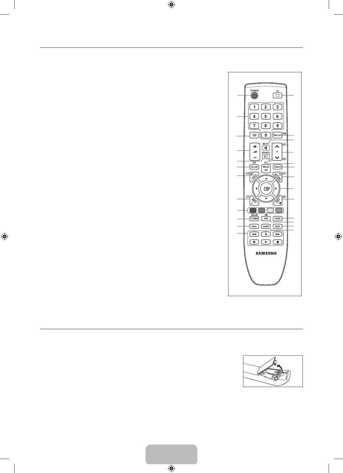
Remote Control
N
You can use the remote control up to a distance of about 23 feet from the TV.
N
The performance of the remote control may be affected by bright light.
N
The product colour and shape may vary depending on the model.
1
POWER : Television Standby
&
MENU : Displays the main on-screen
button.
menu
2
NUMERIC BUTTONS : Press to
*
FAV.CH : Press to switch to your
change the channel.
favourites channels.
3
E
: Performs the same function
(
RETURN : Returns to the previous menu
as the ENTER
E
key of the
)
UP▲/DOWN▼/LEFT◄/RIGHT►
directional keys. When switching
/ ENTER
E
: Use to select on-screen
channels with the numeric buttons,
menu items and change menu values.
and you press the channel number
and then the ENTER
E
key, the
a
EXIT : Press to exit the menu.
channel is immediately switched.
b
P.SIZE : Picture size selection
4
Y
: Press to increase or
c
SRS : SRS TS HD selection.
decrease the volume.
d
SUBT. : Digital subtitle display
5
SOURCE : Press to display and
e
GUIDE : Electronic Programme Guide
select the available video sources.
(EPG) display
6
CH LIST : Displays the Channel List
on screen
Teletext Functions
7
TOOLS : Use to quickly select
frequently used functions.
5
0
: Teletext mode selection (LIST /
FLOF)
8
INFO : Press to display information
on the TV screen.
6
8
: Teletext store
9
COLOURS BUTTONS : Use these
7
4
: Teletext size selection
buttons in the Channel list menus
8
5
: Teletext reveal
etc.
9
Fastext topic selection
!
DUAL : Sound effect selection
0
/
: Alternately select Teletext,
@
Use these buttons in the DMA and
Double, or Mix.
Anynet
+
modes. (
∏
: This remote
#
:
: Exit from the Teletext display
can be used to control recording
on Samsung recorders with the
$
1
: Teletext sub page
Anynet+ feature)
^
2
: Teletext next page
#
TV : Selects the TV mode directly.
3
: Teletext previous page
$
PRE-CH : Enables you to return
&
6
: Teletext index
to the previous channel you were
(
9
: Teletext hold
watching.
a
7
: Teletext cancel
%
MUTE
M
: Press to temporarily cut
off the sound.
^
P
<
/P
>
: Press to change
channels.
¦
Installing Batteries in the Remote Control
1. Lift the cover at the back of the remote control upward as shown in the gure.
2.
Install two AAA size batteries.
N
Make sure to match the ‘+’ and ‘–’ ends of the batteries with the diagram inside the compartment.
3.
Replace the cover.
N
Remove the batteries and store them in a cool, dry place if you won’t be using the
remote control for a long time.
N
If the remote control doesn’t work, check the following:
●
Is the TV power on?
●
Are the plus and minus ends of the batteries reversed?
●
Are the batteries drained?
●
Is there a power outage or is the power cord unplugged?
●
Is there a special uorescent light or neon sign nearby?
1
#
2
3
$
%
4
^
5
&
6
*
7
(
)
8
a
9
0
b
I-II
c
!
d
e
@
BN68-01893F-Eng.indd 5 2009-02-24 �� 2:57:19
Оглавление
- CONTENTS
- GENERAL INFORMATION
- OPERATION
- CHANNEL CONTROL
- PICTURE CONTROL
- SOUND CONTROL
- SETUP
- INPUT / SUPPORT
- ABOUT ANYNET +
- RECOMMENDATIONS FOR USE
- СОДЕРЖАНИЕ
- ОБЩАЯ ИНФОРМАЦИЯ
- ЭКСПЛУАТАЦИЯ
- УПРАВЛЕНИЕ КАНАЛАМИ
- УПРАВЛЕНИЕ ИЗОБРАЖЕНИЯМИ
- УПРАВЛЕНИЕ ЗВУКОМ
- УСТАНОВКА
- ВХОД / ПОДДЕРЖКА
- О ФУНКЦИИ ANYNET +
- РЕКОМЕНДАЦИИ ПО ИСПОЛЬЗОВАНИЮ


