Samsung SCC-B5354: Installation
Installation: Samsung SCC-B5354
8
9
Installation
❚
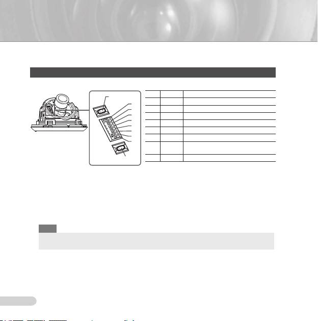
Setting switches
Setting function switches
To set the available functions on your camera, adjust eight switches as shown below:
No Name Brief description
DEC
1 LL Line lock ON/OFF
8
7
2 LSS Sens-up or Low speed shutter ON/OFF
6
3 H-REV Horizontal reverse ON/OFF
5
4 V-REV Vertical reverse ON/OFF
4
5 BLC Backlight compensation ON/OFF
3
2
6 FL Flickerless ON/OFF
1
Automatic switching between color and
7 D/N
black & white ON/OFF
INC
8 AWB Automatic white balance ON/OFF
1. Switch 1 (LL): When this switch is set to OFF, the camera operates in the internal
synchronization mode, while when it is set to ON, the camera operates in the line lock mode.
In the internal synchronization mode, the camera always uses an inside crystal oscillator for
synchronization. However if multiple cameras are connected to a sequential switcher, picture
rolling or flickering may occur when switching from one camera to another. In this case, you
can set this switch to ON to solve this problem.
The line lock mode allows the camera to use the phase of the AC power as the
synchronization reference. In this mode, you can use the phase control buttons(INC/DEC).
Note
When you are using the DC 12V power, set this switch to OFF. The line lock feature will not normally
operate even when the switch is set to ON.
Set the LL switch to ON while the AC power is connected. If any picture roll happens, you have
to adjust the phase using the phase-control buttons. Press the INC or DEC button to increase or
decrease the phase by one degree.
AB68-00687E_Eng.indd 8 2007-08-06 ソタネト 2:09:20

8
ENG
9
2. Switch 2 (LSS): This sens-up mode accumulates the image fields in memory to reduce
noise but increase the brightness and contrast rate. When this switch is set to ON, the
camera automatically switches to a maximum of 128 times of image acquisition speed to
implement a clear picture for darker image.
3. Switch 3 (H-REV): When this switch is set to ON, the camera image is reversed horizontally.
If you want to monitor your site using a mirror, you can use this feature to see the right
image.
4. Switch 4 (V-REV)
: When this switch is set to ON, the camera image is reversed vertically.
If your camera reluctantly displays the vertically reversed image, you can use this feature to
see the right image.
5. Switch 5 (BLC)
: When this switch is set to ON, you can view a clear image even though the
camera faces any excessive light such as sunlight and fluorescent light. When it is set to
OFF, the subject with excessive light is not clearly shown.
6. Switch 6 (FL)
: When this switch is set to ON, the shutter speed is fixed to 1/100 sec (for
NTSC) or 1/120 sec (for PAL) to prevent screen from flickering by the disaccordance
between vertical synchronous frequency (50Hz for NTSC, 60Hz for PAL) and on-and-off
frequency of a light.
7. Switch 7 (D/N)
: When this switch is set to ON, the camera automatically switches between
color and B&W according to the brightness of the vicinity.
8. Switch 8 (AWB): This switch adjusts white balancing. When this switch is set to
ON, this
camera operates in ATW mode, and in case of
OFF, this camera operates in AWC mode.
ATW (Auto Tracking White Balance): The color temperature is automatically adjusted according to the
environmental change. (Approx. 2000°K to 11,000°K)
AWC (Auto White Balance Control): It stores the color temperature just when the switch is changed to
OFF. Accordingly color temperatures are adjusted by the stored value.
Caution
-. The IRIS setting range for the camera is approximately 80 to 120 IRE. It means the camera does not
provide the IRIS full open/close feature but the restricted variation range.
-. Use the camera after setting to the proper level (80 IRE or above) because the IRIS hunting may
occur when the level is 75 IRE or below.
AB68-00687E_Eng.indd 9 2007-08-06 ソタネト 2:09:21
10
11
❚
Connecting cables and changing the settings
Before installing your camera, you have to adjust the lens focus, zoom, and switch settings.
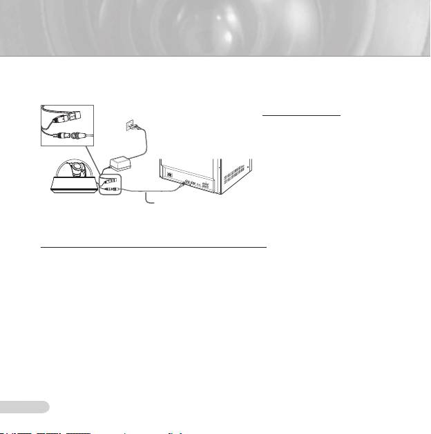
To connect cables
1. Connect the BNC cable
to the Video connector
attached on your camera.
Monitor
2. Connect the BNC cable
to the Video Input on a
monitor.
3. Connect the power adapter
to the Power connector
attached on your camera.
BNC Cable
When the monitor is turned
on, the camera image
appears.
To adjust the lens focus, zoom, and function settings
1. Remove the Cover dome and Inner cover. For more details about the removing procedures,
see “Installation procedure,” in the Installing camera section on the next page.
2. Adjust the focus, zoom, and function settings of your camera using the Focus lever, Zoom
lever, and Switch board while you are viewing the image on the screen.
3. If you want to fix the adjusted focus and zoom, screw up the levers.
AB68-00687E_Eng.indd 10 2007-08-06 ソタネト 2:09:21
10
ENG
11
❚
Installing camera
Before installation
Before installing your camera, you have to read the following cautions:
You have to check whether the location (ceiling or wall) can bear five times the weight of your camera.
Don’t let the cable to be caught in improper place or the electric line cover to be damaged. Otherwise it
may cause a breakdown or fire.
When installing your camera, don’t allow any person to approach the installation site. If you have any
valuable things under the place, move them away.
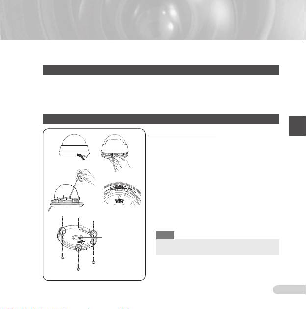
Installation procedure
To install your camera
1
1. Press the Locker button on the bottom of your
camera and remove the Cover dome from the Main
body using the other hand. The Main body and Inner
cover will be exposed to you.
2. To install and adjust your camera, you have to first
remove the Inner cover. To remove the Inner cover
from the Main body, push a long thin screwdriver
2
3
into the narrow spot of the Wing locker and press it
outward to remove the cover.
3. Remove the Mount bracket from the Main body by
rotating the Main body in the UNLOCK direction while
pushing the Lock releaser outward. If it is not easily
done, rotate the Mount bracket in the LOCK direction
while holding small holes on the Mount bracket.
4
4. Fix the Mount bracket to the location (ceiling or wall)
with supplied three screws.
Note
Ceiling mount
opener
The CAMERA FRONT sign on the Mount bracket
should face the camera monitoring area.
AB68-00687E_Eng.indd 11 2007-08-08 ソタネト 6:46:30
12
13
5. When you install the Mount bracket on the ceiling, remove the Ceiling mount opener by pressing
it hard to connect the line attached on your camera through the hole in the ceiling. Otherwise, you
can use the empty space opposite to the CAMERA FRONT sign for line connection.
6. Now attach the Main body to the Mount bracket by rotating it in the LOCK direction after aligning
the Groove mark on the Main body with the wide groove around the CAMERA FRONT inlay.
7. Adjust the camera direction. For more details on the direction control, see “Adjusting the camera
direction,” on the same page. When required to adjust the zoom and focus for your camera, see
“Connecting cables and changing the settings,” on page 10.
8. Attach the Inner cover to the Main body by pressing it until a “click” sound is heard after aligning
two screw holes on the Wing lockers of the Inner cover with two screw holes on the Main body’s
left and right sides.
9. Finally attach the Cover dome to the Main body by pressing it until a “click” sound is heard after
aligning the bump inside the Cover dome with the Groove mark on the Main body.
❚
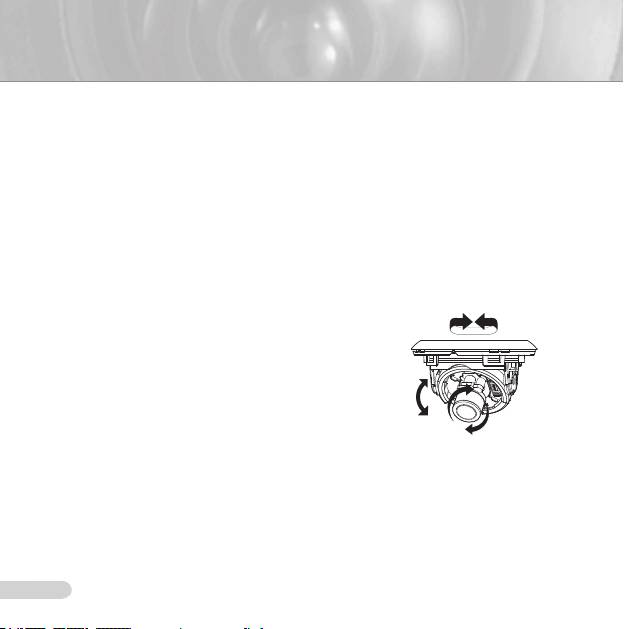
Adjusting the camera direction
When the camera is fixed on the ceiling, you can adjust
Panning
the camera viewing angle. You can rotate your camera
leftward or rightward (Panning), and can change the slope
of your camera upward or downward (Tilting).
In case of panning, the rotation limit of your camera is
set to 355 degree (100 degree clockwise and 255 degree
counterclockwise). The rotation is stopped by the
Stopper
inside of the camera. For panning control, first unfasten
Tilting
two screws located on the bottom and rotate in the
direction you want, and then fasten them to fix the camera.
In case of tilting, you can change the slope of your camera
Lens rotation
from zero to 90 degree. However if the slope angle is
under 17 degree, you can encounter a partial image hide
problem. To fix the location after adjusting the tilting angle, use the Tilt fixing screws
.
To adjust the focus and zoom of your camera, use the
Zoom lever and Focus lever. When
you install the camera on the inclined ceiling or wall, you can rotate the camera lens to see
a correct direction image.
AB68-00687E_Eng.indd 12 2007-08-06 ソタネト 2:09:24
12
ENG
13
SCC-B535X
AB68-00687E_Eng.indd 13 2007-08-06 ソタネト 2:09:26
Оглавление
- Safety Precautions
- Important Safety Instructions
- Contents
- Overview
- Installation
- Appendix A: Specifications for NTSC Standard
- Appendix B: Specifications for PAL Standard
- Меры предосторожности
- Правила техники безопасности
- Содержание
- Краткий обзор видеокамеры
- Установка
- Приложение А: Технические характеристики камеры системы NTSC
- Приложение Б: Технические характеристики камеры системы PAL
- Środki bezpieczeństwa
- Ważne zalecenia dotyczące bezpieczeństwa
- Spis treści
- Wstęp
- Montaż
- Załącznik A : Charakterystyka dla standardu NTSC
- Załącznik B : Charakterystyka dla standardu PAL
