Samsung NX-308: GENERAL DESCRIPTION SECTION
GENERAL DESCRIPTION SECTION: Samsung NX-308

GENERAL
DESCRIPTION
SECTION
1GENERAL 1999.9.15 12:46 PM 페이지1

1GENERAL 1999.9.15 12:46 PM 페이지2

NX-SERIESHYBRID KEY SYSTEM GENERAL DESCRIPTION SECTION
TABLE OF CONTENTS
GENERAL DESCRIPTION
NX-SERIES GENERAL SYSTEM DIAGRAM . . . . . . . . . . . . . . . . . 1-1
1. SYSTEM OVERVIEW . . . . . . . . . . . . . . . . . . . . . . . . . . . . . . . . 1-2
1.1 NX-308 SYSTEM . . . . . . . . . . . . . . . . . . . . . . . . . . . . . . . . . . . . 1-2
1.2 NX-820 SYSTEM . . . . . . . . . . . . . . . . . . . . . . . . . . . . . . . . . . . . 1-2
1.3 NX-1232 SYSTEM . . . . . . . . . . . . . . . . . . . . . . . . . . . . . . . . . . . 1-2
2. NX-SERIES LAYOUT . . . . . . . . . . . . . . . . . . . . . . . . . . . . . . . 1-3
2.1 TOP VIEW . . . . . . . . . . . . . . . . . . . . . . . . . . . . . . . . . . . . . . . . . 1-3
2.2 SIDE VIEW . . . . . . . . . . . . . . . . . . . . . . . . . . . . . . . . . . . . . . . . 1-3
3. SYSTEM CONFIGURATION . . . . . . . . . . . . . . . . . . . . . . . . . . . 1-4
3.1 NX-308 SYSTEM . . . . . . . . . . . . . . . . . . . . . . . . . . . . . . . . . . . . 1-4
3.2 NX-820 SYSTEM . . . . . . . . . . . . . . . . . . . . . . . . . . . . . . . . . . . . 1-4
3.3 NX-1232 SYSTEM . . . . . . . . . . . . . . . . . . . . . . . . . . . . . . . . . . . 1-5
4. HARDWARE DESCRIPTION . . . . . . . . . . . . . . . . . . . . . . . . . . 1-6
4.1 KSU (Key Service Unit) . . . . . . . . . . . . . . . . . . . . . . . . . . . . . . . 1-6
4.2 EXPANSION CARDS & OPTION BOARDS . . . . . . . . . . . . . . . 1-6
4.3 STATION EQUIPMENT . . . . . . . . . . . . . . . . . . . . . . . . . . . . . . . 1-7
5. SPECIFICATIONS . . . . . . . . . . . . . . . . . . . . . . . . . . . . . . . . . . 1-8
5.1 ELECTRICAL SPECIFICATIONS . . . . . . . . . . . . . . . . . . . . . . . 1-8
5.2 DIMENSIONS AND WEIGHTS . . . . . . . . . . . . . . . . . . . . . . . . . 1-8
1GENERAL 1999.9.15 12:46 PM 페이지3

1GENERAL 1999.9.15 12:46 PM 페이지4
NX-SERIESHYBRID KEY SYSTEM GENERAL DESCRIPTION SECTION
5.3 ENVIRONMENTAL LIMITATIONS . . . . . . . . . . . . . . . . . . . . . . .1-8
5.4 CABLE REQUIREMENTS . . . . . . . . . . . . . . . . . . . . . . . . . . . . . 1-8
5.5 SYSTEM TONES AND RINGS . . . . . . . . . . . . . . . . . . . . . . . . . 1-9
5.6 KEYSET LED INDICATIONS . . . . . . . . . . . . . . . . . . . . . . . . . . . 1-10
NX-SERIESHYBRID KEY SYSTEM GENERAL DESCRIPTION SECTION
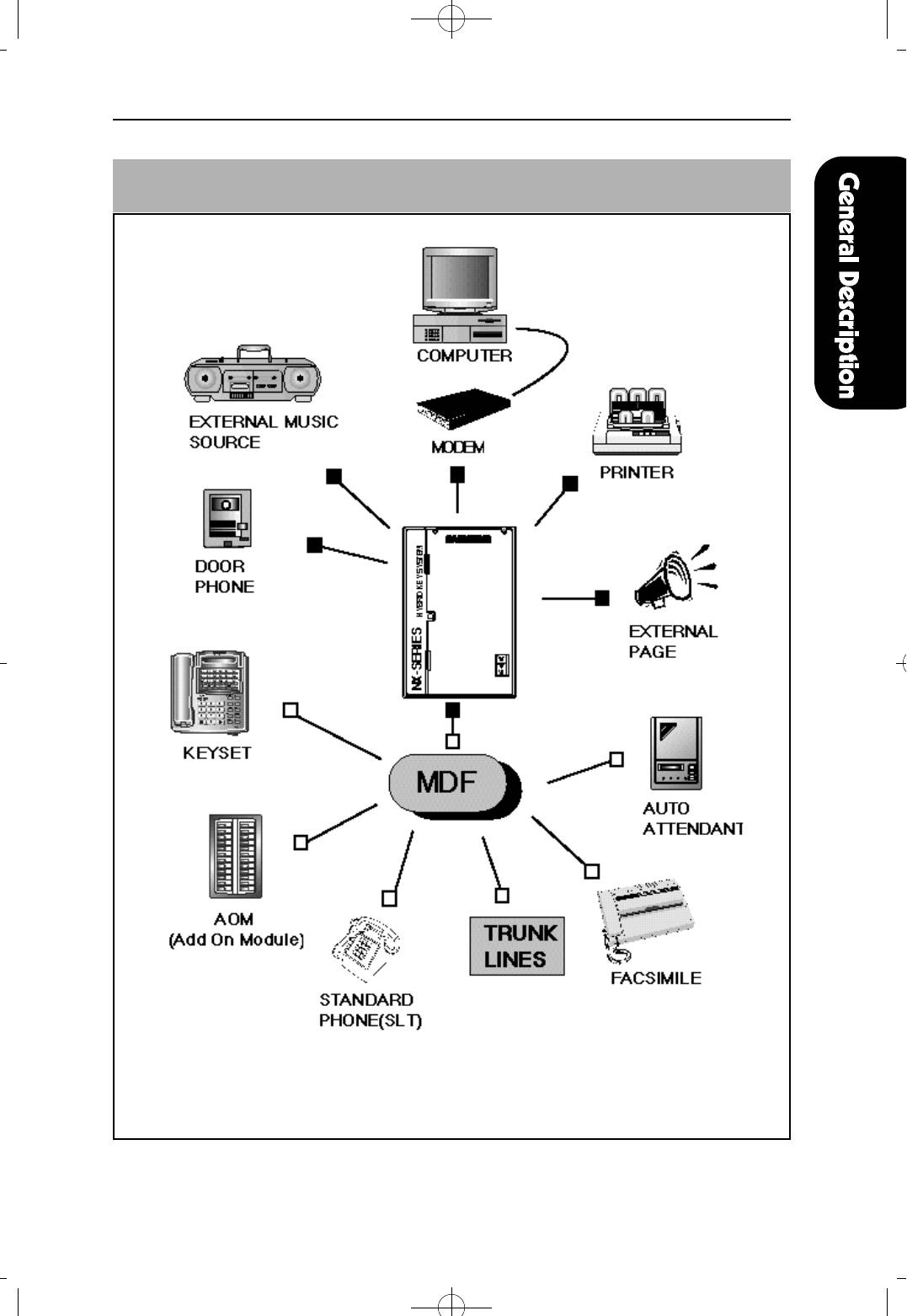
NX-SERIESGENERAL SYSTEM DIAGRAM
1 - 1
1GENERAL 1999.9.15 12:46 PM 페이지5

1GENERAL 1999.9.15 12:46 PM 페이지6
NX-SERIESHYBRID KEY SYSTEM GENERAL DESCRIPTION SECTION
1. SYSTEM OVERVIEW
The NX-series hybrid key system accomodates three kinds of Key Station:
NX-308, NX-820 and NX-1232.
1.1 NX-308 SYSTEM
The NX-308, with a maximum capacity of three telephone C.O. lines and eight
stations, is an analog telephone system designed for the small-sized business.
A powerful H M 6 4 1 8 0 R 1 digital microprocessor controls all speech paths and
system functions. The operating program with default memory is stored in non-
volatile ROM 27C020. Customer data is stored in RAM 62256 and is protected for
up to seven continuous days' loss of system power by a Ni-Cd battery. When AC
power is restored, the Ni-Cd battery is recharged automatically.
1.2 NX-820 SYSTEM
Designed for small to medium-sized businesses, the N X - 8 2 0 is an analog
telephone system featuring a maximum capacity of forty (40) ports, made up of
the combined total of C.O. telephone lines and stations, permitting various
configurations. Comprised of a Key Service Unit, expansion boards, electronic
keysets and conventional single line telephones, the N X - 8 2 0 offers small or
medium-sized business users flexible control of telephone communications. A
powerful HM64180R1 digital microprocessor controls all speech paths and system
functions. The operating program with default memory is stored in non-volatile
ROM 27C020. Customer data is stored in RAM 681000, and is protected for up to
seven continuous days' loss of system power by a Ni-Cd battery. When AC power
is restored, the Ni-Cd battery is recharged automatically.
1.3 NX-1232 SYSTEM
The NX-1232 is an analog telephone system designed for small to medium-sized
business. The NX-1232 system has a maximum capacity of forty eight (48) ports,
made up of the combined total of C.O. telephone lines and stations, permitting
various configurations. Comprised of a Key Service Unit, expansion boards,
electronic keysets and conventional single line telephones, the N X - 1 2 3 2 s y s t e m
offers small or medium-sized business users flexible control of telephone
communications. A powerful HM64180R1 digital microprocessor controls all
speech paths and system functions. The operating program with default memory is
stored in non-volatile ROM 27C020. Customer data is stored in RAM 681000, and
is protected for up to seven continuous days' loss of system power by a Ni-Cd
battery. When AC power is restored, the Ni-Cd battery is recharged automatically.
1 - 2
NX-SERIESHYBRID KEY SYSTEM GENERAL DESCRIPTION SECTION
2. NX-SERIES LAYOUT
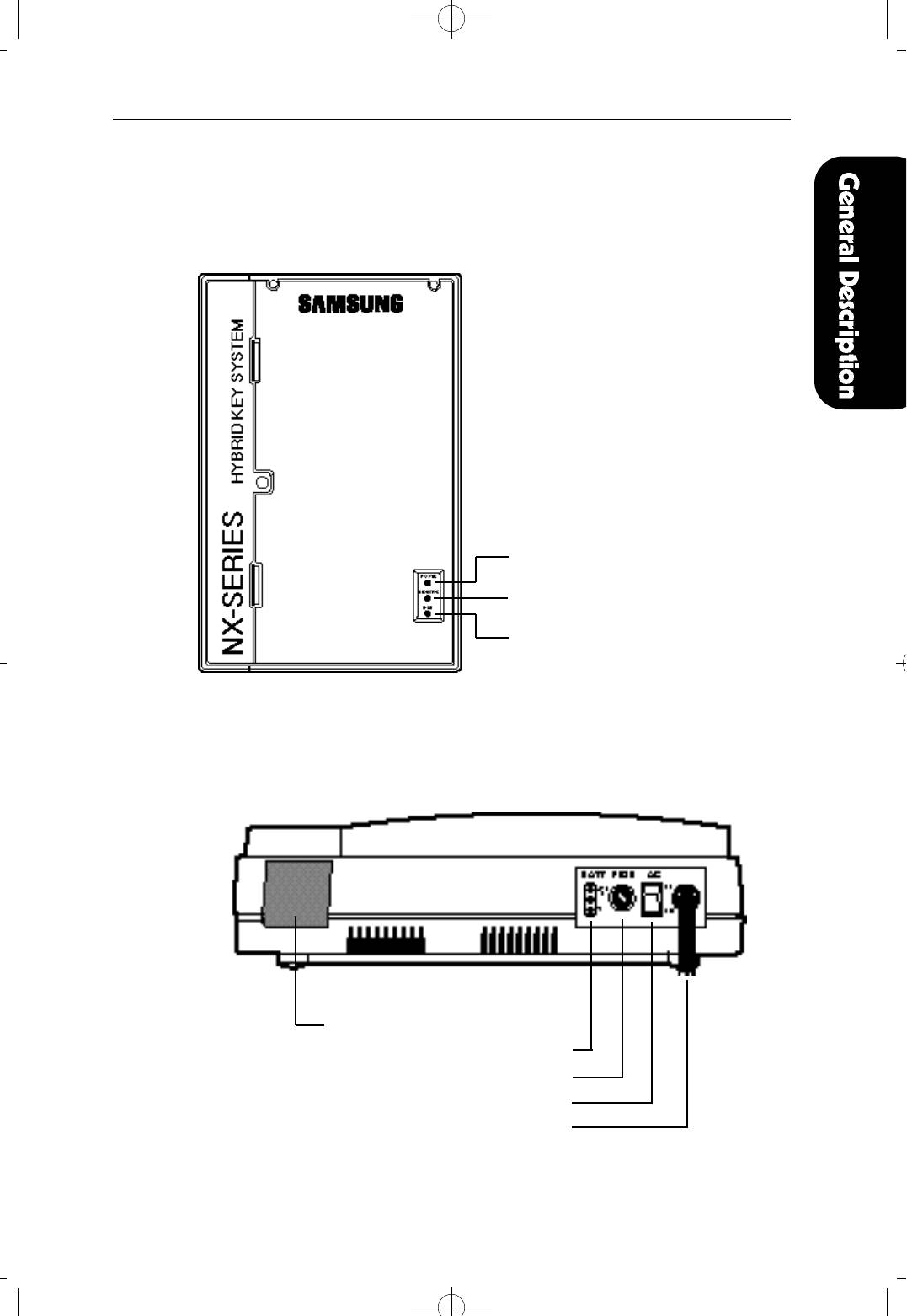
2.1 TOP VIEW
“POWER” LED
“MONITOR” LED
“IDLE” LCD
2.2 SIDE VIEW
MDF Cable Path
External Battery Connector
Fuse Holder
Power Switch
Power Cable
1 - 3
1GENERAL 1999.9.15 12:46 PM 페이지7
1GENERAL 1999.9.15 12:46 PM 페이지8
NX-SERIESHYBRID KEY SYSTEM GENERAL DESCRIPTION SECTION
3. SYSTEM CONFIGURATION
3.1 NX-308 SYSTEM
The basic KSU (Key Service Unit) comes equipped to operate three telephone
lines and eight stations. Station #1 is assigned to be used with a keyset and
stations #2 through #8 are assigned as keysets or single-line telephones.
The NX-SMDR/R-MMC board is the SMDR and REMOTE MMC serial interface,
and the NX-DPH/PAGING board is the door phone and external paging interface.
These optional boards can be installed on the base board
3.2 NX-820 SYSTEM
The basic KSU (Key Service Unit) comes equipped to operate four telephone lines
and twelve stations. Stations #1 through #4 are assigned to be used with keysets and
stations #5 through #12 are assigned for single-line telephones. The NX-820 system
accomodates several kinds of expansion card. The NX-2TRK, NX-4TRK, NX-4KLI,
NX-4SLI, NX-4OPX, NX-8KLI and N X - 8 S L I cards may be installed in any of the three
expansion slots. By combining these cards, the N X - 8 2 0 system can be increased to
its maximum capacity of forty ports. Optionally, the N X - S M D R / R - M M C , N X -
DPH/PAGING, NX-MPD and NX-PRS board can be installed on the base board.
The NX-SMDR/R-MMC board is the SMDR and REMOTE MMC serial interface,
the NX-DPH/PAGING board is the door phone and external paging interface and
the NX-MPD, NX-PRS board are interface for calculating call cost.
But, maximum keyphone part is restricted to twenty four(24) ports although three
NX-8KLI cards are used.
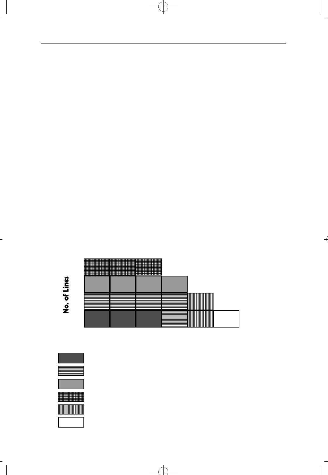
16
12
8
4
4 8 12 20 28 36
No. of Stations
Basic KSU
Basic KSU, one 8 SLI (or 8 KLI) Board and one 4 TRK Card
Basic KSU, one 8 SLI (or 8 KLI) Board and two 4 TRK Cards
Basic KSU and three 4 TRK Cards
Basic KSU, two 8 SLI (or 8 KLI) Boards and one 4 TRK Cards
Basic KSU and three 8 SLI (or 8 KLI) Cards
1 - 4
NX-SERIESHYBRID KEY SYSTEM GENERAL DESCRIPTION SECTION
3.3 NX-1232 SYSTEM
The basic KSU (Key Service Unit) comes equipped to operate eight telephone
lines and sixteen stations. Stations #1 through #8 are assigned to be used with
keysets or single line telephones, and stations #9 through #16 are assigned for
single line telephones. The NX-1232 system accepts several kinds of expansion
cards. The NX-2TRK, NX-4TRK, NX-4KLI, NX-4SLI, NX-4OPX, NX-8KLI, NX-
8SLI cards can be installed in any of the three expansion slots. By combining
these cards, the N X - 1 2 3 2 system can be increased to its maximum capacity of
forty eight ports.
Optionally, the N X - S M D R / R - M M C, NX-DPH/PAGING, NX-MPD and N X - P R S
board can be installed on the base board. The NX-SMDR/R-MMC board is the
S M D R and REMOTE MMC serial interface, the N X - D P H / P A G I N G board is the
door phone and external paging interface and the N X - M P D, N X - P R S board are
interface for calculating call cost.
But, maximum keyphone part is restricted to twenty four(24) ports although three
NX-8KLI cards are used.
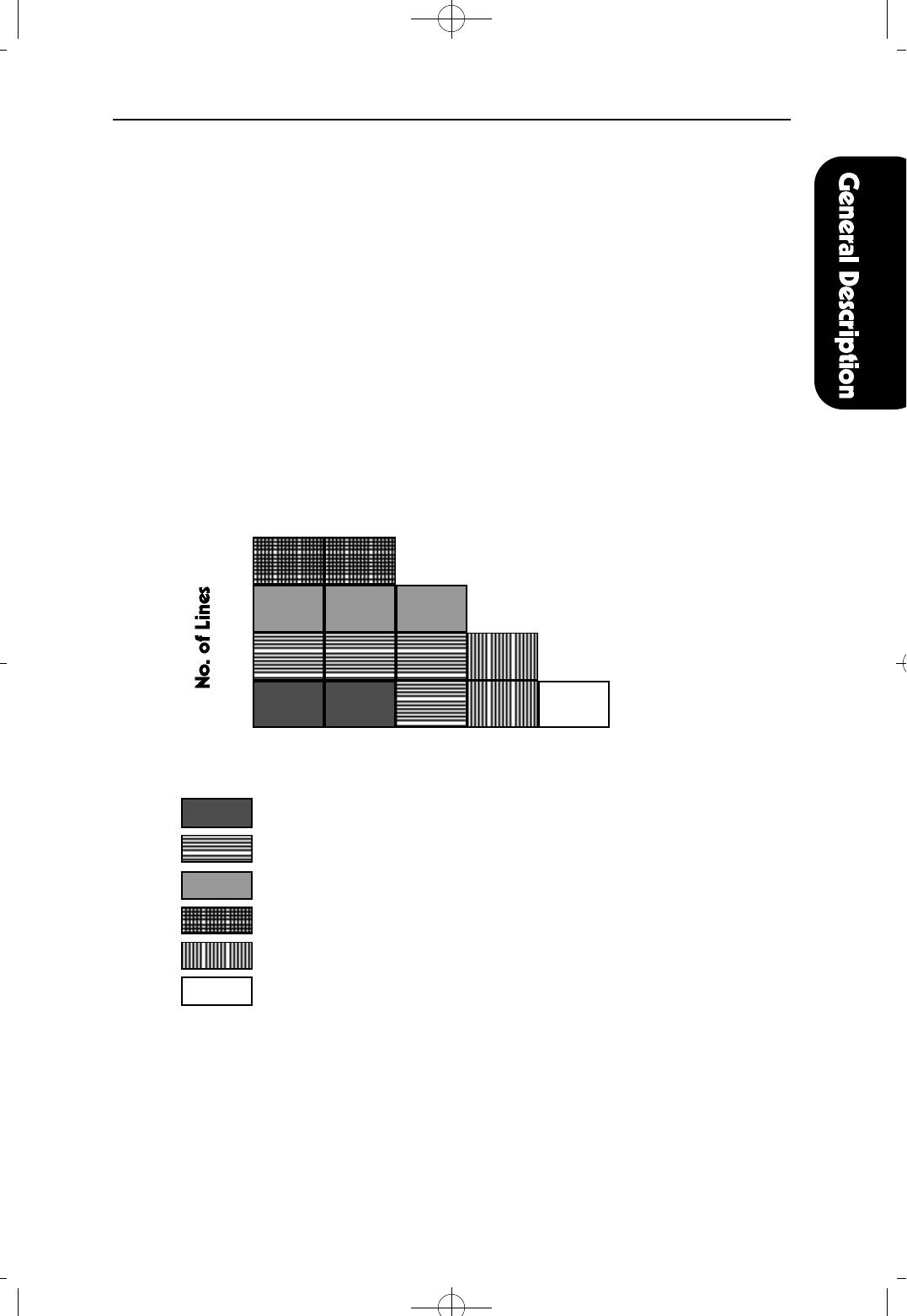
20
16
12
8
8 16 24 32 40
No. of Stations
Basic KSU
Basic KSU, one 8 SLI (or 8 KLI) Board and one 4 TRK Card
Basic KSU, one 8 SLI (or 8 KLI) Board and two 4 TRK Cards
Basic KSU and three 4 TRK Cards
Basic KSU, two 8 SLI (or 8 KLI) Board and one 4 TRK Card
Basic KSU and three 8 SLI (or 8 KLI) Cards
1 - 5
1GENERAL 1999.9.15 12:46 PM 페이지9
1GENERAL 1999.9.15 12:46 PM 페이지10
NX-SERIESHYBRID KEY SYSTEM GENERAL DESCRIPTION SECTION
4. HARDWARE DESCRIPTION
4.1 KSU (Key Service Unit)
The KSU of the NX-series is a single cabinet, wall mounted, metal cased unit,
containing the following:
● Power Supply
● Processing, switching, and customer memory for all ports.
● Internal music source and External music interface
● 2 Power Failure Transfer
● Back-up Battery for memory protection
● Real Time Clock (RTC)
NX-308 SYSTEM NX-820 SYSTEM NX-1232 SYSTEM
3 Trunk interfaces 4 Trunk interfaces 8 Trunk interfaces
1 keyset, 7 Hybrid 4 KTS and 8 SLT 8 hybrid and 8 SLT
station interfaces station interfaces station interfaces
4.2 EXPANSION CARDS & OPTION BOARDS
● NX-2TRKcard provides two loop start trunk interfaces.
▷ can be installed NX-820 and NX-1232 system.
● NX-4TRKcard provides four loop start trunk interfaces.
▷ can be installed NX-820 and NX-1232 system.
● NX-4KLI card provides four ports for keysets.
▷ can be installed NX-820 and NX-1232 system.
● NX-4SLI card provides four SLI ports for industry standard single line telephones.
▷ can be installed NX-820 and NX-1232 system.
● NX-4OPX card provides four OPX line port for industry standard single line
telephones and can be connected to PBX lines.
▷ can be installed NX-820 and NX-1232 system.
● NX-8KLI card provides eight ports for keysets.
▷ can be installed NX-820 and NX-1232 system.
● NX-8SLI card provides eight SLI port for industry standard single line telephones.
▷ can be installed NX-820 and NX-1232 system.
● NX-MPDboard provides two ports for metering pulse detection.
▷ can be installed NX-820 and NX-1232 system.
● NX-PRSboard provides two ports for polarity reverse signal detection.
▷ can be installed NX-820 and NX-1232 system.
● NX-SMDR/R-MMCboard provides two serial ports for SMDR and
REMOTE MMC.
▷ can be installed all NX-SERIES system.
● NX-DPH/PAGINGboard provides two DOOR PHONE interface and one
EXTERNAL PAGING interface.
▷ can be installed all NX-SERIES system.
1 - 6
NX-SERIESHYBRID KEY SYSTEM GENERAL DESCRIPTION SECTION
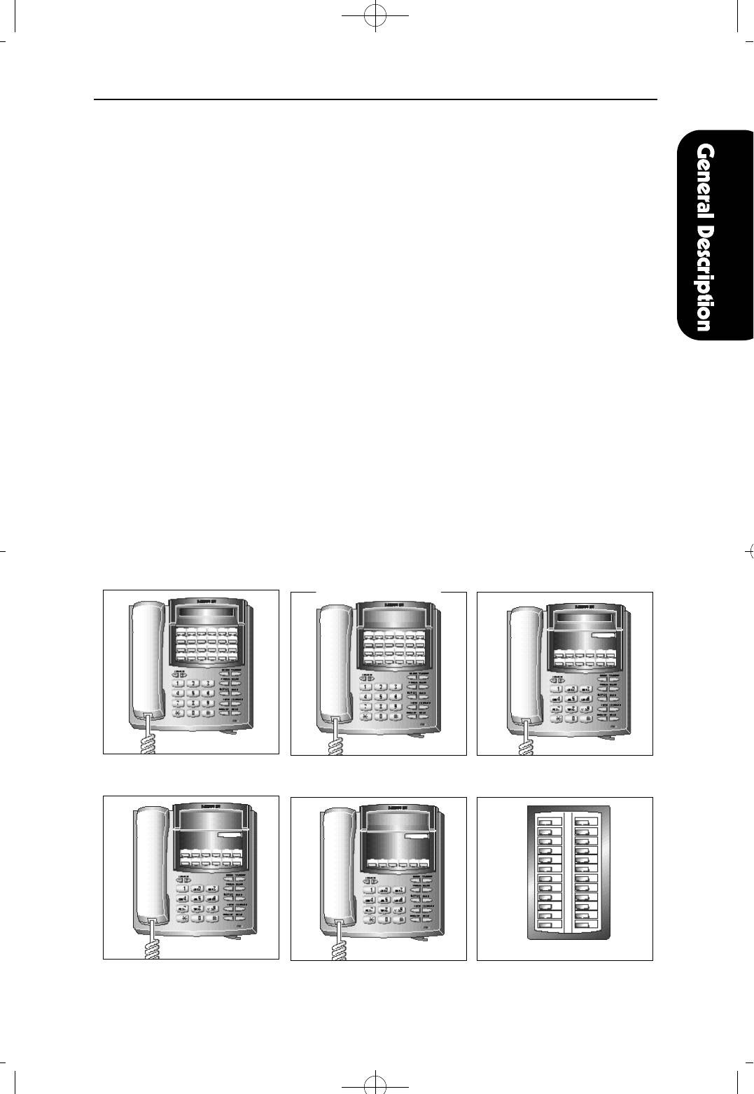
4.3 STATION EQUIPMENT
● Keyset with 24 buttons (NX-24E, NX-24B)
▷ Built-in speakerphone
▷ 24 programmable soft keys (12 with tri-colored LEDs) and 10 fixed-function keys
▷ UP/DOWN buttons for digital control of speaker, handset, and ringer volumes.
▷ Four selectable ring tones per keyset
▷ Desk- or wall- mount
▷ NX-24E keyset with 16 character display
● Keyset with 12 buttons (NX-12E, NX-12B)
▷ Built-in speakerphone
▷ 12 programmable soft keys (6 with tri-colored LEDs) and 10 fixed-function keys
▷ UP/DOWN buttons for digital control of speaker, handset, and ringer volumes.
▷ Four selectable ring tones per keyset
▷ Desk- or wall- mount
▷ NX-12E keyset with 16 character display
● Basic keyset with 6 buttons (NX-6B)
▷ 6 programmable soft keys and 10 fixed-function keys
▷ UP/DOWN buttons for digital control of speaker, handset, and ringer volumes.
▷ Four selectable ring tones per keyset
▷ Desk- or wall- mount
● Add On Module (NX-AOM)
▷ 24 programmable soft keys
NX-24E NX-24B NX-12E
NX-12B NX-6B NX-AOM
1 - 7
1GENERAL 1999.9.15 12:46 PM 페이지11
1GENERAL 1999.9.15 12:46 PM 페이지12
NX-SERIESHYBRID KEY SYSTEM GENERAL DESCRIPTION SECTION
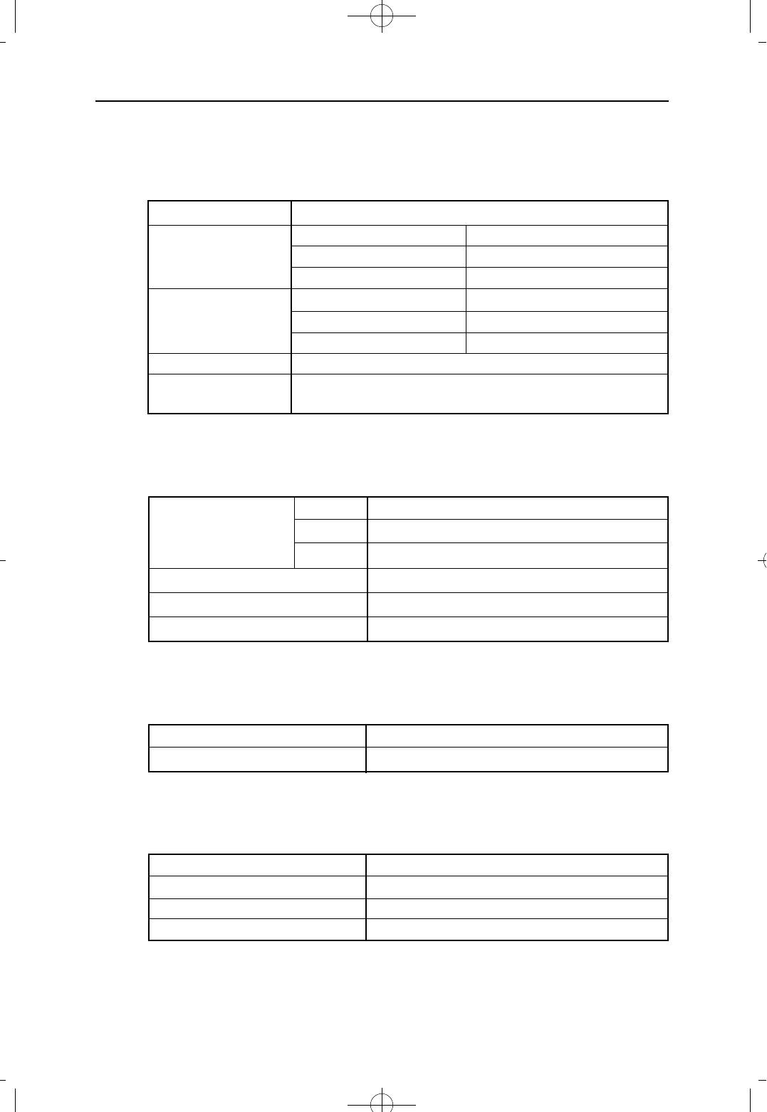
5. SPECIFICATIONS
5.1 ELECTRICAL SPECIFICATIONS
AC INPUT 110/220 VAC, 50/60 Hz
POWER NX-308 50 WATTS MAX
CONSUMPTION NX-820 55 WATTS MAX
NX-1232 80 WATTS MAX
MAX CURRENT NX-308 0.22 AMP
DRAW AT 220 VAC NX-820 0.29 AMP
NX-1232 0.36 AMP
RING GENERATOR AC 80 Vrms, 25 Hz
BATTERY BACKUP
24 VDC, 6 to 26Ah
SUPPLY
5.2 DIMENSIONS AND WEIGHTS
NX-308 530mm(H) x 348mm(W) x 102mm(D), 4.9Kg
KEY SERVICE UNIT NX-820 530mm(H) x 412mm(W) x 140mm(D), 8.9Kg
NX-1232 530mm(H) x 412mm(W) x 140mm(D), 8.9Kg
KEYSET 214mm(H) x 206mm(W) x 150mm(D), 1.1Kg
AOM 214mm(H) x 133mm(W) x 150mm(D), 0.4Kg
DOOR PHONE 158mm(H) x 89mm(W) x 41mm(D), 0.23Kg
5.3 ENVIRONMENTAL LIMITATIONS
OPERATING TEMPERATURES 0℃ - 45℃ (18℃ - 25℃ recommended)
OPERATING HUMIDITY 10% - 90% (non-condensing)
5.4 CABLE REQUIREMENTS
ELECTRONIC SET 2 pair twisted, Max. 400 m (24 AWG)
SINGLE LINE TELEPHONE 1 pair twisted, Max. 1 km (24 AWG)
DOOR PHONE 1 pair twisted, Max. 100 m (24 AWG)
4 OPX B’D 1 pair twisted, Max. 2Km (24 AWG)
1 - 8
NX-SERIESHYBRID KEY SYSTEM GENERAL DESCRIPTION SECTION
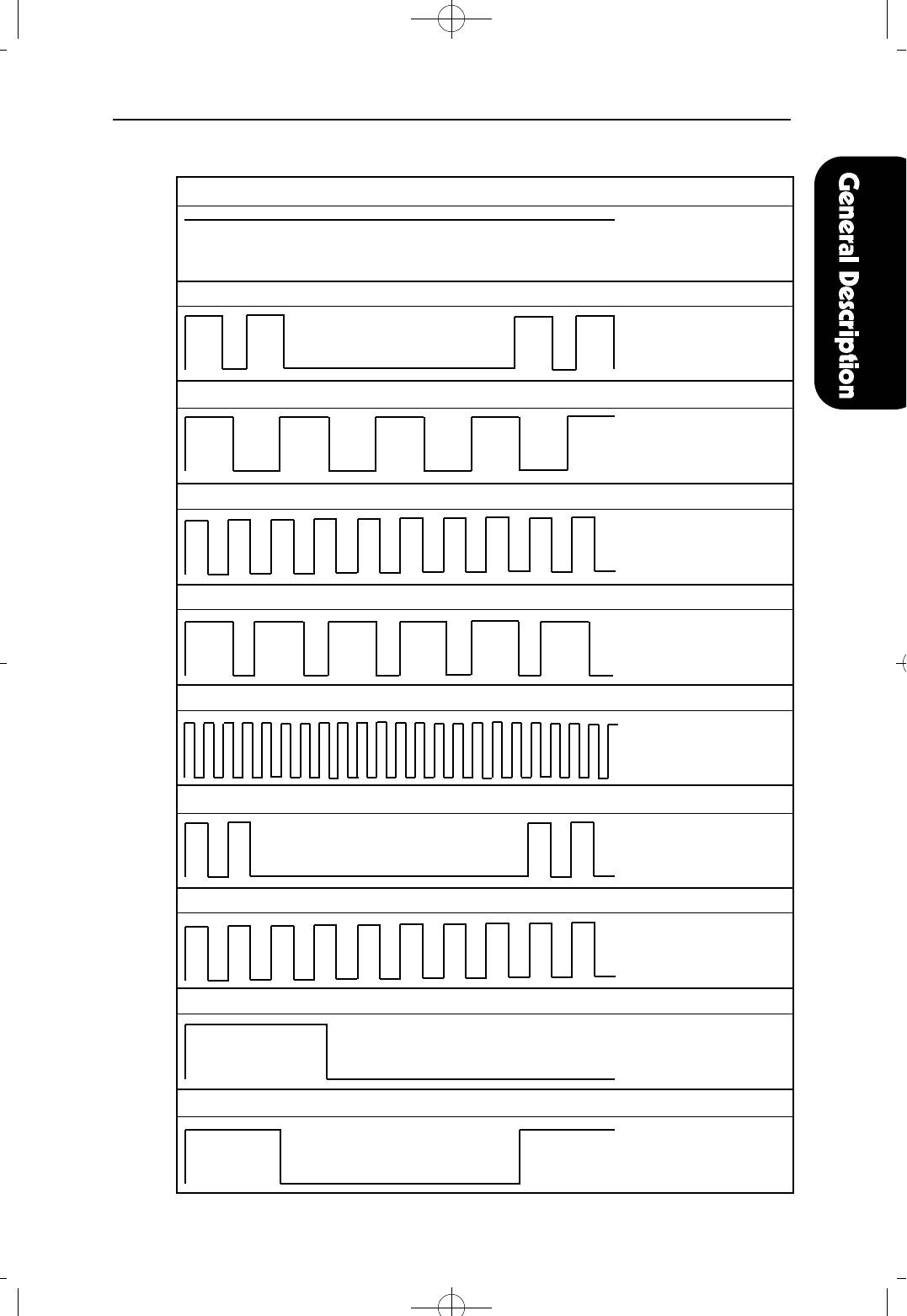
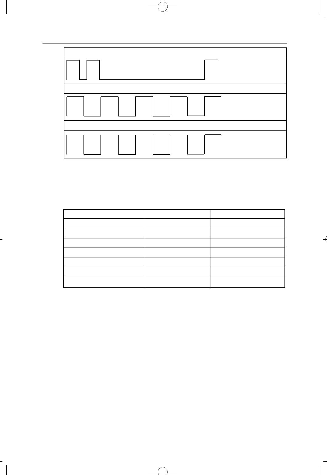
5.5 SYSTEM TONES AND RINGS
DIAL TONE : A steady tone that indicates dialing may begin
CONTINUOUS
RING-BACK TONE :Indicates the station dialed is ringing.
400 ON / 200 OFF/
400 ON / 3000 OFF
BUSY TONE: Indicates the station dialed is busy.
500 ON / 500 OFF/
500 ON / 500 OFF
TRANSFER TONE: Indicates a call is being held and you can dial another party.
200 ON / 200 OFF /
200 ON / 200 OFF
ERROR TONE: Indicates you have done something incorrectly.
500 ON / 250 OFF /
500 ON / 250 OFF
CONFIRMATION TONE: Indicates you have correctly set or canceled a system feature.
100 ON / 100 OFF /
100 ON / 100 OFF
INTRUSION TONE: Indicates you have been barged-in on.
200 ON / 200 OFF /
200 ON / 5000 OFF
MESSAGE WAITING TONE:Indicates messages on SLT type station.
1000 ON / 250 OFF /
1000 ON / 250 OFF
CAMP-ON REMINDER TONE: Indicates a call transfered to you while you are busy.
1000 ON / 15000 OFF /
1000 ON / 15000 OFF
CO LINE RING: Indicates an outside call is ringing on your station.
1000 ON / 3000 OFF /
1000 ON / 3000 OFF
1 - 9
1GENERAL 1999.9.15 12:46 PM 페이지13
1GENERAL 1999.9.15 12:46 PM 페이지14
NX-SERIESHYBRID KEY SYSTEM GENERAL DESCRIPTION SECTION
STATION RING: Indicates an intercom call is ringing on your station.
400 ON / 200 OFF /
400 ON / 3000 OFF
DOORPHONE RING:Indicates a doorphone call is ringing on your station.
500 ON / 500 OFF /
500 ON / 500 OFF
ALARM RING: Indicates an alarm is ringing on your station.
500 ON / 500 OFF /
500 ON / 500 OFF
◆ NOTE : The details may vary according to the regulations or customers
reguest.
5.6 KEYSET LED INDICATIONS
CONDITION LED COLOR LED STATUS
LINE IDLE — OFF
LINE IN USE RED or GREEN STEADY ON
RECALL AMBER FAST FLASH
CALL ON HOLD RED or GREEN SLOW FLASH
RINGING C.O. CALL RED or GREEN FAST FLASH
RINGING INTERNAL CALL GREEN FAST FLASH
DND INDICATION RED STEADY ON
1 - 10
Оглавление
- NX-SERIES
- GENERAL DESCRIPTION SECTION
- INSTALLATION SECTION
- FEATURES SECTION
- PROGRAMMING SECTION
- APPENDIX SECTION
- BACK-UP DATA SHEETS
