Samsung SCC-B5355(S): Overview
Overview: Samsung SCC-B5355(S)
6
7
Overview
❚
About this guide
❚
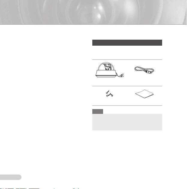
Components
This user guide includes basic instructions for
Checking components in the package
the product. It is recommended that all users
read this guide before use.
Please check your camera and accessories
This guide is divided as follows:
are included in the package. Those
Chapter 1, “Overview,” introduces the user guide
components are as shown below:
and product related information. (This chapter)
Chapter 2, “Installation,” explains how to set and
install the product.
Appendix, “Specifications,” provides the
specifications of the product.
❚
Product overview
Camera Test Monitor Cable
This is the high resolution (540 TV lines) dome
camera equipped with a Vari-focal lens, which
has no dynamic delay when implementing
motion pictures, and provides the features
such as digital noise reduction (DNR) by real-
Tab screw User’s Guide
time CCD defect compensation, low speed
shutter (LSS: Auto x128) to implement clear
Note
picture quality, Day/Night color compensation,
and the like.
The test monitor cable is used to test the camera
by connecting to a portable display. If you really
want to connect the camera to a monitoring
❚
Main features
display, use the BNC cable.
Power: DC 12V/AC 24V
Special functions
Line lock (LL) control
Auto white balancing
Horizontal/vertical image reversing
Flickerless control
Low shutter speed control
Backlight compensation control
Automatic switching between color and black
& white modes
Equipped with vari-focal lens
Auto Iris function
Digital noise reduction (DNR)
Dynamic CCD defect compensation
AB68-00687E_Eng.indd 6 2007-08-06 ソタネト 2:09:09
6
ENG
7
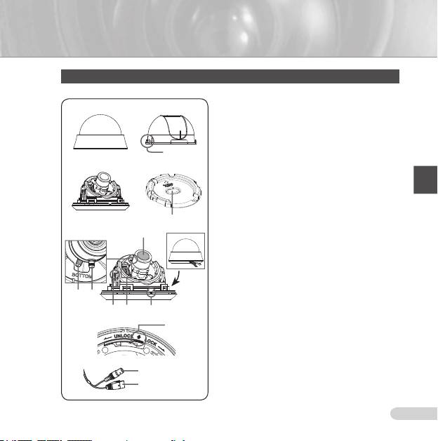
Components of your camera
Your camera has the following components:
1. Cover dome: Covers the inner cover, lens, and main
1 2
body to protect them.
2. Inner cover
: Covers the main body to protect it.
3. Wing locker
: Push a long thin screwdriver into its
narrow spot and press it outward when you want to
remove the inner cover.
3
4. Main body
: Includes a lens, a switch board, a PCB
board, screws, and such.
4
5
5. Mount bracket: Used as a ceiling or wall fixture. It
is fixed using three long tab screws provided in the
package.
6. Ceiling mount opener
: Remove it for line connection
to the ceiling when it is installed on the ceiling.
7. Zoom lever: Using this lever, the lens zoom can be
6
adjusted and fixed.
8. Focus lever: The lens focus can be adjusted by
Lens
@
rotating it left or right. Rotate it clockwise for fixing.
9. Tilt fixing screw: Using this screw, the slope of the
lens can be adjusted and fixed.
10. Switch board
: Includes two kinds of control switches
such as function switches and phase-control switches.
The board has eight function switches in the middle
and two phase-control buttons on each side of the
7
8
function switch area.
11. Groove mark: To attach the
Main body to the Mount
9 0 !
bracket, align this groove mark on the Main body with
the wide groove in the CAMERA FRONT side on the
#
Mount bracket.
12. Locker
: Used to open or close the Cover dome. To
open the cover dome, press the locker.
13. Lock releaser
: Push it outward and rotate the main
body in UNLOCK direction when you want to remove
Video connector
$
the Mount bracket from the Main body or to remove
the installed camera from the Mount bracket.
Power connector
14. Cable: Connect the Video connector to BNC cable
and Power connector to power adapter.
AB68-00687E_Eng.indd 7 2007-08-06 ソタネト 2:09:12
Оглавление
- Safety Precautions
- Important Safety Instructions
- Contents
- Overview
- Installation
- Appendix A: Specifications for NTSC Standard
- Appendix B: Specifications for PAL Standard
- Меры предосторожности
- Правила техники безопасности
- Содержание
- Краткий обзор видеокамеры
- Установка
- Приложение А: Технические характеристики камеры системы NTSC
- Приложение Б: Технические характеристики камеры системы PAL
- Środki bezpieczeństwa
- Ważne zalecenia dotyczące bezpieczeństwa
- Spis treści
- Wstęp
- Montaż
- Załącznik A : Charakterystyka dla standardu NTSC
- Załącznik B : Charakterystyka dla standardu PAL
