Karcher ICC 2 D ADV STAGE IIIa: Shutdown Maintenance and care
Shutdown Maintenance and care: Karcher ICC 2 D ADV STAGE IIIa
-
10
Connect the suction nozzle to the suc-
tion hose.
Set the dry run speed to approx. 1800
1/min.
Note
The motor rpm can be called via the multi-
functional display.
Turn on the working hydraulics (1st lev-
el).
Press switch for raising the suction
mouth.
–
1. step = raise the suction opening
–
2. step = switch on/off the side-brushes
Raise waste container.
Cover the suction pipe with a plate
when sucking in leaves.
Lower waste container.
Shift the water supply from sweeping to
leaf suction operations.
Turn on the suction turbine (1st level).
Switch on the spray water.
Adjust the water flow using the valve.
Remove the covering on the suction
pipe.
Shift the water supply from leaf suction
to sweeping operations.
몇
Warning
The appliance must be secured against
slippage during transport.
Turn ignition key to "0" and remove it.
Lock parking brake.
Secure the wheels of the machine with
wheel chocks.
Secure the appliance with tension
straps at the fastening eyes on the left
and the right.
몇
Warning
Risk of damage! The front towing eye
should not be used to fasten the appliance.
Danger
When carrying out rescue work on public
highways, wear warning clothing when
working close to passing traffic.
Danger
The hydro-static drive of the sweeper per-
mits towing out of the danger area only for
a few metres at walking speed. Do not
move the sweeper at a speed higher than
walking speed.
Danger
The appliance is not suitable for crane
loading.
Note
Make sure the brush-system is not dam-
aged while towing.
Drain off spray water.
Empty waste container.
Fasten the towing rope to the towing
eye in the front or the rear.
Drag the appliance on to the transport
vehicle.
Note
It is easier to move the appliance when the
bypass valve is opened.
Open the bypass valve using the hand
gear from the tool box or a flat spanner
(SW 9).
If the sweeper is going to be out of service
for a longer time period, observe the follow-
ing points:
Park the sweeper on an even surface.
Raise the side-brushes to prevent the
bristles from being damaged.
Turn ignition key to "0" and remove it.
Secure sweeper to prevent it rolling
away, lock parking brake.
Tank up the fuel tank fully.
Change the engine oil and the oil filter.
Drain off the spray water if frost is ex-
pected and check whether is adequate
anti-frosting agent in the cooling water.
Empty the water tank and the pipe sys-
tem.
Disconnect battery.
Charge battery approx. every 2 months.
Clean the inside and outside of the
sweeper.
Park the machine in a safe and dry
place.
First switch off the appliance and re-
move the ignition key before performing
any cleaning or maintenance tasks on
the appliance, replacing parts or switch-
ing over to another function.
Pull out the battery plug or clamp the
battery while working on the electrical
unit.
–
Maintenance work may only be carried
out by approved customer service out-
lets or experts in this field who are famil-
iar with the respective safety
regulations.
–
Mobile appliances used for commercial
purposes are subject to safety inspec-
tions according to VDE 0701.
Park the sweeper on an even surface.
Empty waste container.
Raise the suction opening and the side-
brushes.
Lock parking brake.
몇
Warning
Risk of damage! The electrical components
in the engine room should not be cleaned
using a high-pressure jet.
Clean appliance daily after finishing work.
Note
Do not use aggressive cleaning agents.
After leaf suction operations
Transport
Towing
Bypass valve (accessory)
Shutdown Maintenance and care
General notes
Cleaning
Cleaning the appliance
32 EN
-
11
Shift the water supply to the side-brush-
es and suction opening to operating
with high pressure cleaning.
Turn on the high-pressure cleaner.
Raise waste container.
Remove the hand-spray gun.
Wind off the high pressure hose.
Clean the waste container.
Clean the perforated plate of the water
drain on both the sides.
Clean the sealing areas of the suction
channel.
Clean the side-brushes.
Clean the suction opening.
Clean the bulk waste flap.
If the hose connection between the waste
container and the suction opening is
blocked, then proceed as follows:
Remove the suction hose from the claw
coupling under the vehicle.
Open the hand wheel of the valve by
turning it in anti-clockwise direction.
Connect the hoses at the claw coupling
to the water supply and rinse.
Remove the connection to the water
supply and join the hose back to the
suction opening.
Close by turning the hand wheel of the
valve in clockwise direction.
Open the clamps of the covering grid.
Remove the covering grid.
1 Cooler for air-conditioner (accessory)
2 Oil cooler
3 Water cooler
–
Clean the cooler only when the motor
has been switched off.
–
Use a low-pressure water jet or com-
pressed air to clean the cooler accord-
ing to the procedure described above.
–
Do not clean using a high-pressure
cleaner.
Start the appliance.
Set the dry run speed to approx. 1800
1/min.
Turn on the working hydraulics (1st lev-
el).
Place the water hose in front of the suc-
tion opening.
Switch on the suction turbine and the
side-brushes (2nd step).
Note
Let the suction turbine run for approx. 2
minutes.
Raise waste container.
Switch off engine.
Clean the covering grid.
Raise waste container.
Switch off engine.
Danger
Risk of injury! Wait for at least 1 minute until
the blower wheel stops rotating.
Remove the upper screws (1).
Remove the strip (2).
Loosen the lower screws (3).
Remove the covering grid and clean the
suction channel.
Note
The operating meter of the motor shows
the timing of the maintenance intervals.
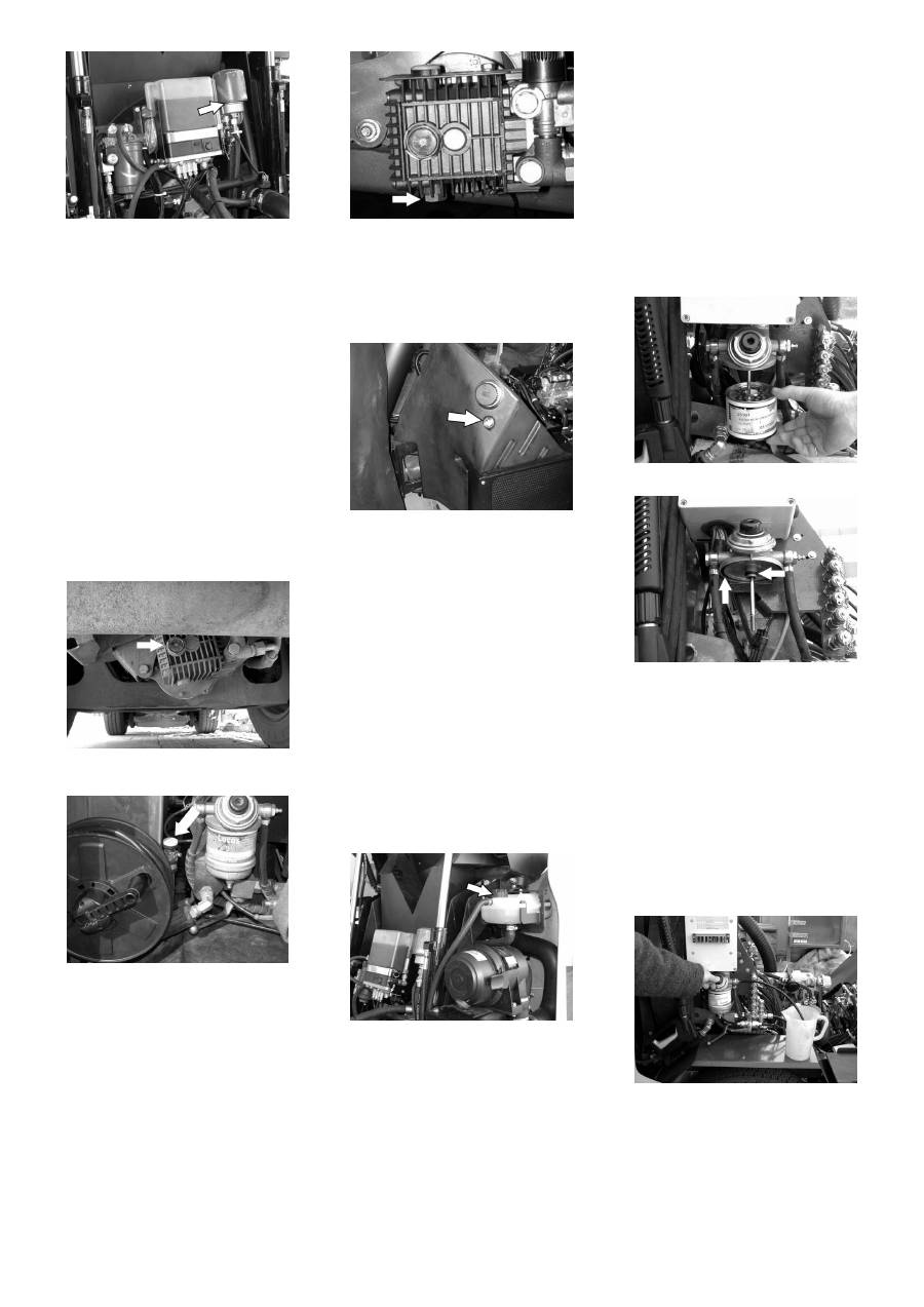
Daily maintenance:
Clean the lighting.
Check engine oil level.
Check the hydraulic oil level.
Clean the cooler.
Clean the covering grid of the suction
channel.
Check cooler water level.
Check the air filter, clean if required.
Check tube air filter/ motor.
Check the side-brushes and suction
opening for wear and wrapped belts.
Check function of all operator control el-
ements.
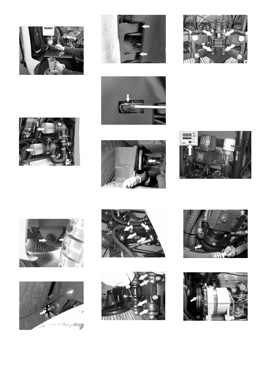
Weekly maintenance:
Check sealing washer of suction pipe.
Check washers of the waste container.
Grease the bearings.
Check tyre pressure.
Clean the hose connections.
Clean the cooler
Cleaning the suction channel and the
waste container
Cleaning the covering grid of the suction
channel
Cleaning the suction channel
Maintenance intervals
Maintenance by the customer
33 EN
-
12
Check water level of wiper.
Clean water filter (frequently depending
on the water quality).
Check oil level of the water pump.
Check functioning and easy movement
of the bulk-waste flap.
Check rollers to see that they move
easily.
Lubricate the side-brush system.
Additional maintenance to be carried out
every 50 operating hours:
Check the function of the immobilizing
brake.
Check the hydraulic system for leakag-
es.
Check V-Belt for wear and tear.
Check coolant to see that it does not
frost.
Check hoses and clamps.
Check wheels.
Check connections and conduits.
Additional maintenance to be carried out
every 150 operating hours:
Change engine oil.
Replace motor oil filter inlay.
Change the air filter.
Empty the wate separator at the fuel fil-
ter.
Check battery acid level.
Clean the ventilation slits of the lights.
For description, see section on Mainte-
nance work.
Note
Where maintenance is carried out by the
customer, all service and maintenance
work must be undertaken by a qualified
specialist. If required, a specialised Kärch-
er dealer may be contacted at any time.
Maintenance to be carried out after 50 op-
erating hours:
Carry out initial inspection.
Additional maintenance to be carried out
every 150 operating hours:
Note
In order to safeguard warranty claims, all
service and maintenance work during the
warranty period must be carried out by the
authorised Kärcher Customer Service in
accordance with the maintenance booklet.
Preparation:
Park the sweeper on an even surface.
Raise waste container completely.
Lower the side-brushes.
Turn ignition key to "0" and remove it.
Lock parking brake.
Danger
When carrying out repairs on public high-
ways, wear warning clothing when working
close to passing traffic.
Danger
Risk of injury! While carrying out mainte-
nance tasks, tilt the waste container fully
upward and lower the brush system to re-
move the pressure from the hydraulic sys-
tem.
Danger
Risk of injury! Secure the lid while working
inside the waste container.
Danger
Risk of injury due to engine overrun. Once
the engine has been switched off, wait for 5
seconds. Stay well clear of the working
area for this time.
Allow the machine sufficient time to cool
down before carrying out any mainte-
nance and repair work.
–
Cooling water is hot.
–
Do not touch any hot parts, such as the
drive motor and exhaust system.
Please observe the following warning notes
when handling batteries:
Danger
Follow accident prevention regulations as
well as DIN VDE 0510, VDE 0105 T.1.
Danger
Risk of explosion! Do not put tools or similar
on the battery, i.e. on the terminal poles
and cell connectors.
Danger
Risk of injury! Ensure that wounds never
come into contact with lead. Always clean
your hands after having worked with batter-
ies.
Danger
Risk of fire and explosion!
–
Smoking and naked flames are strictly
prohibited.
–
Rooms where batteries are charged
must have good ventilation because
highly explosive gas is emitted during
charging.
Danger
Danger of causticization!
–
Rinse thoroughly with lots of clear water
if acid gets into the eye or comes in con-
tact with the skin.
–
Then consult a doctor immediately.
–
Wash off the acid If it comes in contact
with the clothes.
Raise waste container.
Insert battery in battery mount.
Screw on mounts on battery base.
Connect pole terminal (red cable) to
positive pole (+).
Connect pole terminal to negative pole
(-).
Note
Before removing the battery, make sure
that the negative pole lead is disconnected.
Check that the battery pole and pole termi-
nals are adequately protected with pole
grease.
몇
Warning
Regularly check the fluid level in acid-filled
batteries.
–
The acid in a fully charged battery has a
specific weight of 1.28 kg/l at a temper-
ature of 20 °C.
–
The acid in a partially discharged bat-
tery has a specific weight between 1.00
and 1.28 kg/l.
–
The specific weight of the acid must be
uniform in all cells.
Unscrew all cell caps.
Take a sample from each cell using the
acid tester.
Put the acid sample back into the same
cell.
Maintenance by Customer Service
Maintenance Works
General notes on safety
Please do not release engine
oil, fuel oil, diesel and petrol
into the environment. Protect
the ground and dispose of
used oil in an environmentally-
clean manner.
Safety notes regarding the batteries
Observe the directions on the
battery, in the instructions for
use and in the vehicle operat-
ing instructions!
Wear an eye shield!
Keep away children from acid
and batteries!
Risk of explosion!
Fire, sparks, open light, and
smoking not allowed!
Danger of causticization!
First aid!
Warning note!
Disposal!
Do not throw the battery in the
dustbin!
Installing and connecting the battery
Check fluid level in the battery and ad-
just if required
34 EN
-
13
Where fluid level is too low, top up cells
to the mark provided with distilled wa-
ter.
Charge battery.
Screw in cell caps.
Danger
Risk of injury! Comply with safety regula-
tions on the handling of batteries. Observe
the directions provided by the manufacturer
of the charger.
Danger
Charge the battery only with an appropriate
charger.
Disconnect battery.
Connect positive terminal cable from
the charger to the positive pole connec-
tion on the battery.
Connect negative terminal cable from
the charger to the negative pole con-
nection on the battery.
Plug in mains connector and switch on
charger.
Charge battery using lowest possible
level of charging current.
Note
When the battery is charged, first remove
the charger from the mains and then dis-
connect it from the battery.
Park the sweeper on an even surface.
Connect air pressure testing device to
tyre valve.
Check air pressure and adjust if re-
quired.
Danger
When carrying out repairs on public high-
ways, wear warning clothing when working
close to passing traffic.
Danger
Risk of injury!
Park the sweeper on an even surface.
Remove ignition key.
Check stability of ground. Also secure
the machine with wheel chock(s) to pre-
vent it rolling away.
Lock parking brake.
Check tyres
Check tyre contact face for foreign ob-
jects.
Remove objects found.
Use suitable, commercially available
materials to carry out tyre repairs.
Note
Observe the manufacturer's recommenda-
tions. The journey may be resumed provid-
ing that the directions supplied by the
product manufacturer have been observed.
The tyre/wheel change should nonetheless
be carried out as soon as possible.
Intake point for the jack (front wheels)
Use the corresponding intake delivered
along with the vehicle.
Intake point for the jack (rear wheels)
Position vehicle jack at the appropriate
mounting point for the front or rear
wheel.
Loosen wheel nuts/ wheel bolts.
Raise machine using vehicle jack.
Remove wheel nuts/ wheel bolts.
Remove wheel.
Mount spare wheel.
Insert the wheel nuts/ wheel bolts.
Lower machine using vehicle jack.
Tighten the wheel nuts/ wheel bolts.
Note
Use a suitable commercially available vehi-
cle jack.
Danger
Risk of burns!
Allow engine to cool down.
Wait for at least 5 minutes after switch-
ing off the engine before checking the
engine oil fill level.
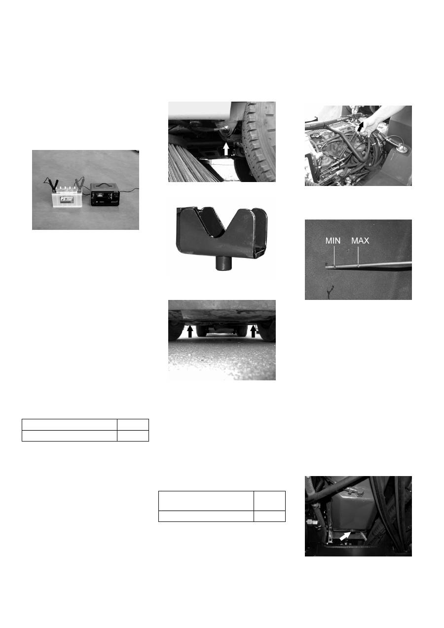
Raise waste container.
Pull out oil dipstick.
Wipe off oil dipstick and insert.
Pull out oil dipstick.
Read the value of the oil level.
Insert the oil dip again.
–
The oil level must lie between “MIN“
and “MAX“ marking.
–
Add motor oil if the oil level is below the
"MIN" marking.
–
Do not fill oil above the "MAX" marking.
Loosen the screw cap of the oil filling
opening.
Fill in motor oil.
Oil grade: see Technical Data
Close oil filler opening.
Wait at least 5 minutes.
Check engine oil level.
Danger
Risk of burns due to hot oil!
Ready a catch bin for appr. 6 litre oil.
Allow engine to cool down.
Unscrew oil drain plug.
Loosen the screw cap of the oil filling
opening.
Drain off oil.
Charging battery
Check the tyre pressure
Air pressure, front
3,75 bar
Air pressure, rear
4,75 bar
Replacing wheel
Tightening torque for front
tyres
140 Nm
Tightening torque for rear tyres 120 Nm
Check engine oil level and top up, if re-
quired
Change the motor oil and the oil filter
35 EN
-
14
Unscrew the oil filter.
Clean the intake and sealing areas.
Coat the washer of the new oil filter with
oil before fitting it.
Fit in the new oil filter and tighten it by
hand.
Screw in the oil drain screw along with
the new washer.
Note
Tighten the oil drain screw using a torque
wrench to 25 Nm.
Fill in motor oil.
Oil grade: see Technical Data
Close oil filler opening.
Let the motor run for approx. 10 sec-
onds.
Check engine oil level.
The oil level must be within the viewing
glass.
Refill oil:
Clean the filling area.
Loosen the screw cap of the oil filling
opening.
Refill oil.
Close oil filler opening.
Check oil level.
Oil change:
Ready a catch bin for appr. 1 litre oil.
Unscrew oil drain plug.
Oil grade: see Technical Data
The oil level must be within the viewing
glass.
Clean the filling area.
Loosen the screw cap of the oil filling
opening.
Refill hydraulic oil.
Oil grade: see Technical Data
Check all hydraulic hoses and connec-
tions and ensure that they are leak-
proof.
Only Kärcher Customer Service is author-
ised to carry out maintenance tasks on the
hydraulic unit.
Danger
Danger of scalding by boiling water! Let the
cooler cool down for at least 20 minutes.
Fill in cold water in the cooling water
compensation tank.
If the motor is cold:
–
Cooling water level must be above the
lower marking.
If the motor is warm:
–
Cooling water level must be below the
upper marking.
–
The percentage of anti-frost agent in
the cooling water should not be more
than 50%.
Danger
Risk of explosion!
–
Do not carry out maintenance tasks in
closed rooms.
–
Smoking and naked flames are strictly
prohibited.
Switch off engine.
Raise waste container.
Keep a suitable catch bin ready.
Loosen the fuel filter casing.
Empty the fuel filter casing.
Remove the fuel filter casing.
Clean or replace fuel filter.
Replace washers.
Fit the fuel filter again.
Check fuel tubes and clamps for dam-
ages and make sure they are leak-
proof.
Deaerate the fuel system
Raise waste container.
Insert the hose on the deaeration
screw.
Turn the deaeration screw by one rota-
tion.
Keep a suitable catch bin ready.
Pump until fuel free of air bubbles is re-
leased.
Close the deaeration screw.
Check oil level in the water pump; refill
and change oil
Check hydraulic oil level and refill hy-
draulic oil
Check hydraulic unit
Check water cooler and maintain it
Clean and replace fuel filter
Deaerating the fuel system
36 EN
-
15
Raise waste container.
Insert the hose on the drain screw.
Turn the drain screw by one rotation.
Keep a suitable catch bin ready.
Close the release screw.
Raise waste container.
Loosen the fasteners of the air filter
casing.
Remove covering lid.
Remove and clean the filter cartridge.
Insert new filter cartridge, if required.
Clean the screw cap.
Replace the screw cap and clamp it.
Fix the fasteners of the air filter casing.
Grease the left end right lubrication nip-
ples of the front axle.
Grease the left end right lubrication nip-
ples of the rear axle.
Grease the lubrication nipple at the
swivel joint.
Grease the lubrication nipple at the
steering cylinder.
Grease the lubrication nipple at the
steering cylinder.
Grease the lubrication nipple at the
brush-system (8x).
Only 4-brush system:
Lift the covering flaps at the swivel
heads.
Grease the swivel joints (8x).
Only 4-brush system:
Lift the covering flaps at the swivel
heads.
Grease the swivel joints (8x).
The central lubrication unit automatically lu-
brications all the lubrication points at spec-
ified intervals.
Note
It is necessary to do an additional round of
greasing after the appliance has been
cleaned thoroughly.
Press the button on the central lubrica-
tion unit.
The central lubrication unit will not lubricate
the brush-system.
Check the V-Belt of the spray-water
pump for damage and wear and tear.
Raise waste container.
Check the V-Belt of the lighting system
for damage and wear and tear.
Refill water for the wiper.
Emptying the water separator of the fuel
system
Cleaning and replacing the fuel filter
Greasing the bearings
Greasing the brush-system
Central lubrication unit (accessory)
Checking the V-Belt
Refilling wiper water
37 EN
-
16
Clean/ set the spray nozzles:
Clean the spray nozzle opening (1) us-
ing a wire.
Adjust the spraying direction by turning
the spray head with a wire.
Change the wiper blades:
Remove the fastening screw (2).
Change the wiper blade.
Lock parking brake.
The side-brushes lift up.
Clip side brush on to driver and screw
on.
Changing the wiper blade with the intake:
Loosen the central screw.
Remove the wiper blade.
Fix in the new wiper blade.
Changing the wiper blade without the in-
take:
Loosen the hexagonal nuts:
Remove the wiper blade.
Fix in the new wiper blade.
Check tyre pressure and adjust if re-
quired.
Set the idle running for the motor rpm
setting to 1600-1800 1/min.
The side-brushes lift up.
Drive sweeper on to a smooth, even
surface covered with a visible layer of
dust or chalk.
Lower side-brushes and allow them to
briefly rotate.
The side-brushes lift up.
Drive machine backwards.
Check sweeping mirror.
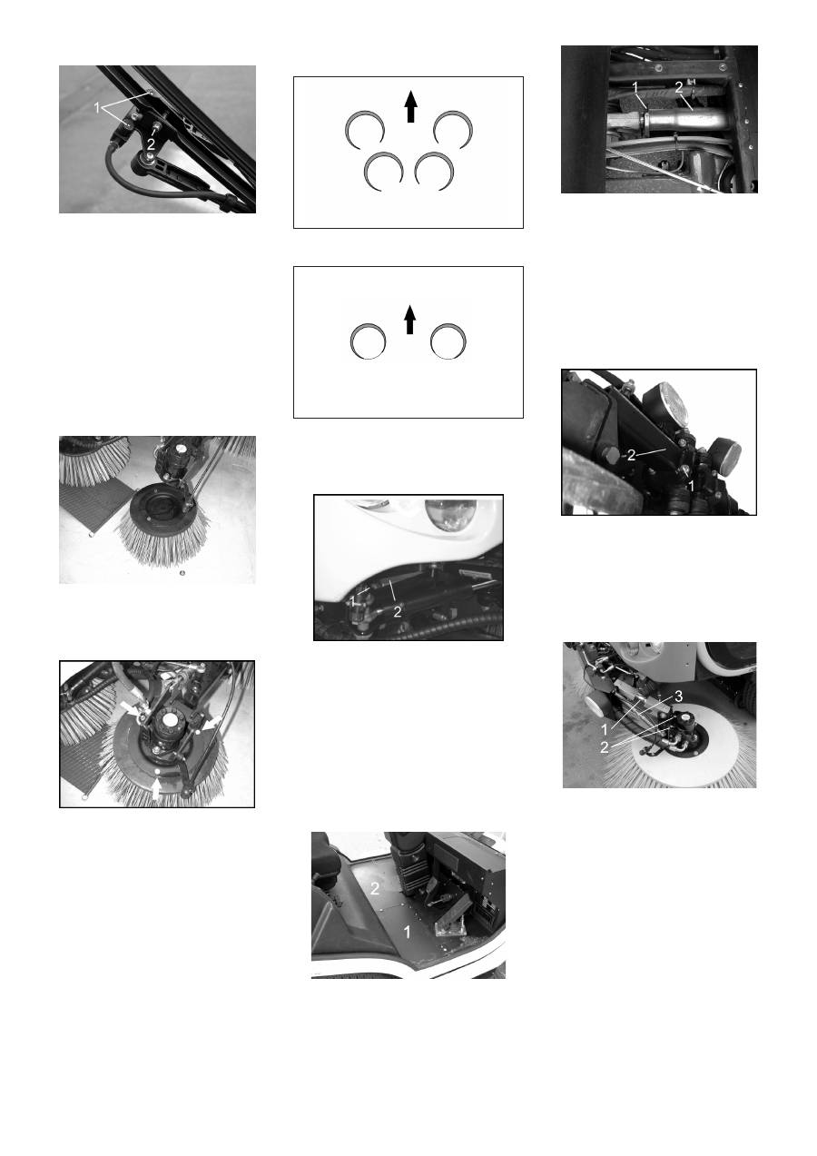
Contact surfaces of the side-brushes dur-
ing optimal setting (4-brush system).
Contact surfaces of the side-brushes dur-
ing optimal setting (2-brush system).
Loosen the fastening screw (1).
Adjust the side inclination of the side-
brushes by adjusting the holder (2).
Note
Always set the rear side-brushes first be-
cause changes to the rear inclination will
have an effect on the inclination of the front
brushes.
Remove floor mat.
Remove the floor plates (1) and (2).
Loosen the fastening screw (1).
Adjust the inclination of the side-brush-
es in the drive direction by adjusting the
holder (2).
Note
Set the left and right side always at the
same value.
Loosen the fastening screws (1) of the
side-brush attachment .
Adjust the inclination of the side-brush-
es in the drive direction by turning the
holder (2).
Loosen the fastening screws (1) and (2)
of the side-brush attachment .
Set the inclination of the side-brushes.
Increase/ reduce the brush pressure by
adjusting the setting screw (3).
Note
In the 4-brush system, the contact pressure
can only be set for the front side-brushes.
Maintaining the wiper
Replacing side brush
Checking the sweeping mirror of the
side-brushes
Adjusting the side inclination of the rear
side-brushes (only 4-brush system)
Adjusting the inclination of the rear side-
brushes in drive direction (only 4-brush
system)
Adjusting the inclination of the front
side-brushes in drive direction (only 4-
brush system)
Adjusting the inclination of the side-
brushes (only 2-brush system)
Setting the brush contact pressure
38 EN
-
17
Unscrew the tank coupling.
Connect a textile hose to the tank cou-
pling and hydrant.
Fill up the water tank:
Note
Fill up the water tank until it overflows.
Note
If the water tank had got completely empty,
then it is necessary to deaerate the spray
water system after the tank has been filled
up.
Open the valve until bubble free water
comes out.
Now close the valve.
Open the drain screw below the water
tank.
Note
Ensure that the water flowing out does not
cause any damage.
Turn off tap (1).
Unscrew the water filter casing (2).
Clean or replace the water filter.
Clean the water filter casing.
Check rubber washers.
Install the water filter.
Turn on the tap (1).
Unscrew the union joint (1).
Pull out the spray nozzle (2).
Clean the spray nozzle.
Adjusting the sealing strip:
Loosen the fastening screws of the
sealing strip.
Drain off the suction opening.
Adjust the sealing strip on the side and
the rear so as to have a distance of 10
mm from the floor.
Tighten the fastening screws of the
sealing strip.
Replacing the sealing strip:
Loosen the fastening screws of the
sealing strip.
Remove the stabilising plate.
Remove the sealing strip.
Insert the new sealing strip and fasten it
with screws along with the stabilising
plate.
Drain off the suction opening.
Adjust the sealing strip.
Tighten the fastening screws of the
sealing strip.
Remove wheel.
Remove the fastening nuts of the run-
ning rollers.
Replace the running rollers.
Replace the fastening nuts of the run-
ning rollers.
Remove the fastening screws of the
slide bar.
Replace the side bar.
Fasten the slide bar.
Adjusting the sealing strip:
Loosen the screws.
Drain off the suction opening.
Adjust the rear running rollers (3) in
such a way that the side sealing strip (1)
has a floor clearance of 20 mm at the
rear.
Filling up the water tank
Deaerating the spray-water system
Emptying the water tank
Cleaning and replacing the water filter
Cleaning the spray nozzles on the side-
brushes
Setting and replacing the sealing strip of
the suction opening (only 4-brush sys-
tem)
Changing the running rollers of the suc-
tion opening (only 4-brush system)
Changing the slide bar of the bulk waste
flap (only 4-brush system)
Setting and replacing the sealing strip of
the suction opening (only 2-brush sys-
tem)
39 EN
Оглавление
- Inhaltsverzeichnis
- Funktion Bestimmungsgemäße Ver- wendung
- Bedien- und Funktionselemente
- Bedienung
- Vor Inbetriebnahme
- Stilllegung Pflege und Wartung
- Zubehör
- Hilfe bei Störungen
- Technische Daten
- EG-Konformitätserklärung
- Contents
- Function Proper use
- Operating and Functional Elements
- Operation
- Before Startup
- Shutdown Maintenance and care
- Accessories
- Troubleshooting
- Technical specifications
- EC Declaration of Conformity
- Table des matières
- Fonction Utilisation conforme
- Eléments de commande et de fonction
- Utilisation
- Avant la mise en service
- Remisage Entretien et maintenance
- Accessoires
- Assistance en cas de panne
- Caractéristiques techniques
- Déclaration de conformité CE
- Indice
- Funzione Uso conforme a destinazione
- Elementi di comando e di funzione
- Uso
- Prima della messa in funzione
- Fermo dell'impianto Cura e manutenzione
- Accessori
- Guida alla risoluzione dei guasti
- Dati tecnici
- Dichiarazione di conformità CE
- Inhoudsopgave
- Functie Reglementair gebruik
- Elementen voor de bediening en de functies
- Bediening
- Voor de inbedrijfstelling
- Stillegging Onderhoud
- Toebehoren
- Hulp bij storingen
- Technische gegevens
- EG-conformiteitsverklaring
- Índice de contenidos
- Función Uso previsto
- Elementos de operación y funcionamiento
- Manejo
- Antes de la puesta en marcha
- Parada
- Cuidados y mantenimiento
- Accesorios
- Ayuda en caso de avería
- Datos técnicos
- Declaración de conformidad CE
- Índice
- Funcionamento Utilização conforme o fim a que se destina a máquina
- Elementos de comando e de funcionamento
- Manuseamento
- Antes de colocar em funcio- namento
- Desactivação da máquina Conservação e manutenção
- Acessórios
- Ajuda em caso de avarias
- Dados técnicos
- Declaração de conformidade CE
- Indholdsfortegnelse
- Funktion Bestemmelsesmæssig‚ anvendelse
- Betjenings- og funktionselementer
- Betjening
- Inden ibrugtagning
- Afbrydning/nedlæggelse Pleje og vedligeholdelse
- Tilbehør
- Hjælp ved fejl
- Tekniske data
- EU-overensstemmelseser- klæring
- Innholdsfortegnelse
- Funksjon Forskriftsmessig bruk
- Betjenings- og funksjonelementer
- Betjening
- Før den tas i bruk
- Sette bort Pleie og vedlikehold
- Tilbehør
- Feilretting
- Tekniske data
- EU-samsvarserklæring
- Innehållsförteckning
- Funktion Ändamålsenlig användning
- Manövrerings- och funktionselement
- Handhavande
- Före ibruktagande
- Nedstängning Skötsel och underhåll
- Tillbehör
- Åtgärder vid störningar
- Tekniska data
- Försäkran om EU-överens- stämmelse
- Sisällysluettelo
- Toiminta Käyttötarkoitus
- Ohjaus- ja käyttölaitteet
- Käyttö
- Ennen käyttöönottoa
- Seisonta-aika Hoito ja huolto
- Tarvikkeet
- Häiriöapu
- Tekniset tiedot
- EU-standardinmukaisuusto- distus
- Πίνακας περιεχομένων
- Λειτουργία Χρήση σύμφωνα με τους κα - νονισμούς
- Στοιχεία χειρισμού και λειτουργίας
- Χειρισμός
- Πριν τη θέση σε λειτουργία
- Διακοπή της λειτουργίας Φροντίδα και συντήρηση
- Εξαρτήματα
- Αντιμετώπιση βλαβών
- Τεχνικά χαρακτηριστικά
- Δήλωση Συμμόρφωσης των Ε . Κ .
- İ çindekiler
- Fonksiyon Kurallara uygun kullan ı m
- Kullan ı m ve çal ı ş ma elemanlar ı
- Kullan ı m ı
- Cihaz ı çal ı ş t ı rmaya ba ş lama- dan önce
- Durdurma Koruma ve Bak ı m
- Aksesuar
- Ar ı zalarda yard ı m
- Teknik Bilgiler
- AB uygunluk bildirisi
- Оглавление
- Назначение Использование по назначе - нию
- Описание элементов управления и рабочих узлов
- Управление
- Перед началом работы
- Эксплуатация
- Вывод из эксплуатации Уход и техническое обслу - живание
- Принадлежности
- Помощь в случае неполадок
- Технические данные
- Заявление о соответствии ЕС
- Spis tre ś ci
- Funkcja U ż ytkowanie zgodne z prze- znaczeniem
- Elementy urz ą dzenia
- Obs ł uga
- Przed pierwszym uruchomie- niem
- Wy łą czenie z eksploatacji
- Czyszczenie i konserwacja
- Akcesoria
- Usuwanie usterek
- Dane techniczne
- Deklaracja zgodno ś ci UE
