Siemens DE1821515: en
en: Siemens DE1821515
en
8
Installation instructions
Installation
Install the continuous-flow heater as described in the
I.
Unpacking/Removing the cover
illustrated section. Observe the instructions in the text.
Unpack the appliance and check for transport-related ■
The illustrations can be found in the centre of the instruction
damage.
manual.
■
Please dispose of the packaging, and if applicable, the old
appliance in an environmentally-friendly manner.
Safety information
II.
Preparations for installation
Risk of electric shock!
Switch off the mains voltage supply immediately if
Important: Only use the supplied installation set.
a fault occurs.
The supplied water connection nozzles must be installed!
We do not accept liability for damage resulting from ■
■
Shut off water supply. The electrical connection (connec-
failure to heed these instructions.
tion cable) must be disconnected from the power supply.
Unscrew the fuse or switch off the circuit breaker.
The continuous-flow heater may only be connected ■
and put into operation by a qualified professional.
III.
Wall mounting
Never open the appliance without disconnecting the ■
The continuous-flow heater must be mounted on the ■
power supply beforehand.
wall. Attach it if necessary on the lower adjustable screws.
The statutory regulations of the respective country, as ■
■
The distance to the wall is variable. You can compensate
well as those of the local electricity and water suppliers,
for any unevenness of the wall's surface.
must be adhered to.
■
The grommet must tightly surround the connection cable.
■ I appliance and
The continuous-flow heater is a Class
If it is damaged during mounting, the openings must be
must be connected to the protective earth.
provided with watertight sealing.
■
The appliance must be permanently connected to installed
IV.
pipes. The conductor cross-section must comply with
Water connection
the installed appliance power.
The continuous-flow heater must be vented. The ■
■ : Earthed water pipes may give the appearance of
Caution
warm water tap must be opened and the appliance
a connected protective earth.
must be flushed out thoroughly for 1 minute with
at least 6 litres of water.
■
To guarantee compliance to relevant safety regulations,
an all-pole separator must be fitted during installation.
V.
The contact opening must be at least 3 mm.
Electrical connection/Mounting
The continuous-flow heater is only suitable for closed ■
The electrical supply terminal can be fitted at the top or ■
(pressurized) operation.
bottom. The sheath of the connection cable must extend
for at least 40 mm into the appliance.
The tap and outlet fittings must be approved for operation ■
with closed (pressurized) continuous-flow heater systems.
Set the power using the power selector switch before
connecting the wires to the mains connection terminal:
The continuous-flow heater can be operated with cold or ■
pre-warmed water (for example, from a solar energy unit
■
Set DE 1821515 and DE 5151821 to 18 kW (down) or
water supply). Observe the technical data and the special
21 kW (up).
accessories for this purpose.
■
Set DE 2427515 or DE 5152427 to 24 kW (down) or
■
The continuous-flow heater is only suitable for connection
27 kW (up).
to DVGW (German Technical and Scientific Association for
The set power must be marked on the ratings plate.
Gas and Water) approved plastic pipes.
■
Now screw the wires tightly into the mains connection
The continuous-flow heater may only be installed in a ■
terminal.
frost-free room.
Disconnect the electrical connection cable from the ■
supply and shut off the water supply before connect-
ing the appliance!
■
Connect the water supply and then connect the elec-
trical supply.
■
Only make the openings which are required for instal-
lation on the rear of the appliance. If the appliance is
reinstalled, the unused openings must be provided with
watertight sealing.
■
Do not touch electrically live parts after installation.
en
VI.
A
If the continuous-flow heater does not have sufficient
Startup/additional information
water flow due to low water line pressure in your do-
The device is compliant to IEC 61000-3-12.
mestic plumbing system, remove the flow-rate
limiter.
First start-up
B
Priority circuit for the combination with electrical
■
Switch on the fuses.
storage heaters:
For operation with a priority circuit, a special load
Setting the temperature. ■
shedding relay BZ 45L20 (special accessory) is re-
Starts rinsing: Open the warm water tap and allow water ■
quired. Other existing load shedding relays, with the
to flow for at least 1 minute (flow-rate at least 6 litres per
exception of electronic load shedding relays, may
minute). Only then (for safety reasons) will the appliance
malfunction.
begin to heat.
Tip: Should the appliance not start because of a reduced
C
The control electronics must be coded when operated
with a load shedding relay.
flow-rate, remove the perlator, shower head or similar before
start and repeat the process.
■
Remove the flow-rate limiter (see Fig. A) with low water
pressure.
■
Explain the operation of the continuous-flow heater to
the user.
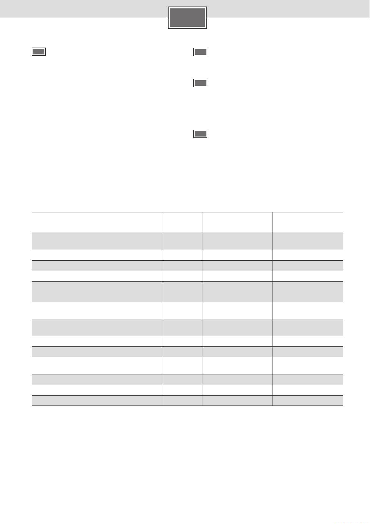
Technical data
DE 1821515
DE 2427515
DE 5151821
DE 5152427
18
24
Rated output
[kW]
21
27
Rated voltage
[V] 400 400
Fuse protection
[A] 32 40
2
Minimum conductor cross-section
[mm
]4 6
Warm water flow at rated output
with temperature increase from
9.9
13.2
12 °C to 38 °C [l/min]
11.6
13.9
5.4
7.2
12 °C to 60 °C [l/min]
6.3
7.6
Start-up flow
[l/min] 2.6 2.6
Start-up flow pressure *
[MPa (bar)] 0.025 (0.25) 0.025 (0.25)
Application area in water
specific electric resistance at 15 °C
[Ωcm] ≥ 1 300 ≥ 1 300
Rated pressure
[MPa (bar)] 1.0 (10.0) 1.0 (10.0)
Maximum permissible supply temperature
[°C] 55 55
Maximum mains impedance at connection point
[Ω] ≤ 0.44 ≤ 0.244
* The pressure loss on the mixer must also be added
Operation with prewarmed water (solar heated)
Important: The cold water supply temperature must not be
higher than 55 °!
The continuous-flow heater can only heat prewarmed water
to a max. of 60 °C. If the cold water supply exceeds a tem-
If the cold water supply exceeds a temperature of 60 °C, a
perature of 55 °C, the water will not be warmed any further.
circuit breaker will trigger and shut the appliance off. There-
fore, the residential plumbing must be equipped with a ther-
mostatic premixer (e. g. special accessory BZ 45T20) that will
limit the cold water supply temperature to a max. of 55 ° by
appropriately mixing in cold water.
9
en
10
236
99
Special accessories
20
Pipe kit ■ BZ 45U20: for use of the continuous-flow heater
as an under sink appliance
■ BZ 45L20:
Priority switch (load shedding relay)
for operation with a priority circuit
Mounting kit ■ BZ 45K23: for surface mount installation
472
332
388
Thermostatic premixer ■ BZ 45T20: for installation in the
domestic plumbing when using preheated water
G
1
2
A
42
100
115
Operating instructions
Operating the continuous-flow
heater
Please read the operating instructions carefully before
you use the appliance!
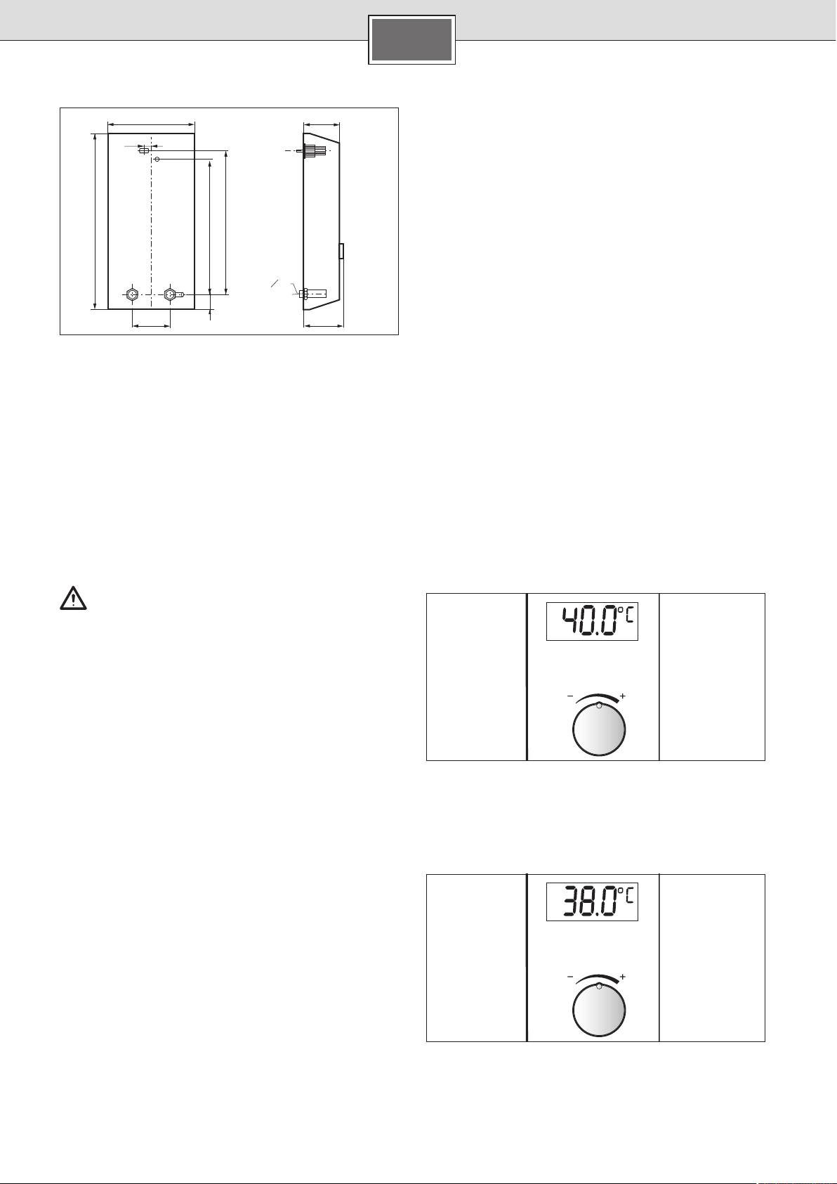
The default temperature for the water temperature after
setting the first start-up or a power failure is 40 °C.
Safety information
Selecting shower temperature
■
This appliance is intended for domestic use or for house-
Select the required temperature with the rotary knob used to
hold-based non-commercial applications. Household-
vary the desired temperature from 20 °C to 60 °C in steps of
based applications include, e.g. usage in employees
0.5 °C.
catering facilities for shops, offices, agricultural and
other commercial operations, as well as usage by guests
Info: The temperature shown in the display is the water tem-
of guest houses, small hotels and similar residential
perature inside the appliance. The temperature of the water
establishments.
leaving the tap can vary from this due to heat losses in the
pipework.
Risk of electric shock!
Switch off the mains voltage supply immediately if
a fault occurs.
■
We do not accept liability for damage resulting from
failure to heed these instructions.
■
The continuous-flow heater may only be connected
and put into operation by a qualified professional.
■
Repairs may only be undertaken by a suitably qualified
specialist to avoid potential sources of danger.
■
The continuous-flow heater may only be installed in a
frost-free room.
■
Persons (including children) with diminished bodily, sen-
Conserving energy and water
sory or mental perception, or those who lack knowledge or
experience should not operate the appliance, unless they
Mixing in of cold water in the fitting requires unnecessary
are monitored or have received instruction concerning use
water and energy. You should therefore set the desired tem-
of the appliance by persons responsible for their safety.
perature directly on the continuous-flow heater and then
■
Keep children away from the appliance. Please moni-
open the water tap.
tor children to ensure that they do not play with the
appliance.
■
The mixer and the warm water pipe may be hot.
Please switch off all fuses immediately if a malfunction ■
occurs. Immediately shut off the cold water supply to the
appliance should it leak. The malfunction can only be re-
paired by a specialist or an authorised service agent.
Your new appliance
The electronic continuous-flow heater “electronic comfort
plus” is intended exclusively for heating water which flows
through the appliance.
Pre-warmed water
The continuous-flow heater switches on and heats the water
The continuous-flow heater can be operated with pre-
when the warm water tap is opened. It switches off as soon as
warmed water (for example from a solar energy unit).
the tap is closed.
en
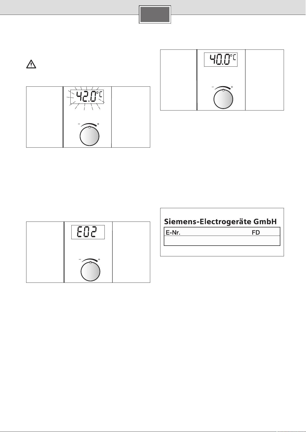
The meaning of display indications
Flashing display
11
Start-up after power failure
Risk of scalding!
If the temperature display flashes, the temperature of the
water leaving the tap is higher than the set temperature.
Open the warm water tap fully and allow a minimum wa- ■
ter flow of 6 litres/minute.
Cleaning
Only wipe off the appliance using a moist cloth. Do not ■
use acidic or abrasive cleaning materials.
The supply temperature from the domestic system is too
high, e. g. water from a solar energy unit.
Do not use a steam cleaner. ■
The thermostatic premixer in the domestic supply must be
set accordingly to lower temperatures.
Customer Service
Error signals
We ask you to always provide the E-No. and the FD-No. of
your appliance when calling in a customer service engineer.
Sometimes e. g. E02 (or E03 to E14) appears in the display
You will find the numbers on the inner side of the fold up
due to a very minor problem. Please try to eliminate the fault
operating panel on the continuous-flow heater.
according to guidelines given in the chapter "A fault, what to
do?". You will save yourself the cost of an unnecessary visit
by customer service personnel.
Using the appliance after switching
off the water supply
■
Switch off the appliance (unscrew the fuse in the house
electrical installation).
Open the warm water tap and keep it open until the air ■
has been completely forced out of the water pipe.
Switch the fuse back on again. ■
The appliance is now ready to operate.
en
12
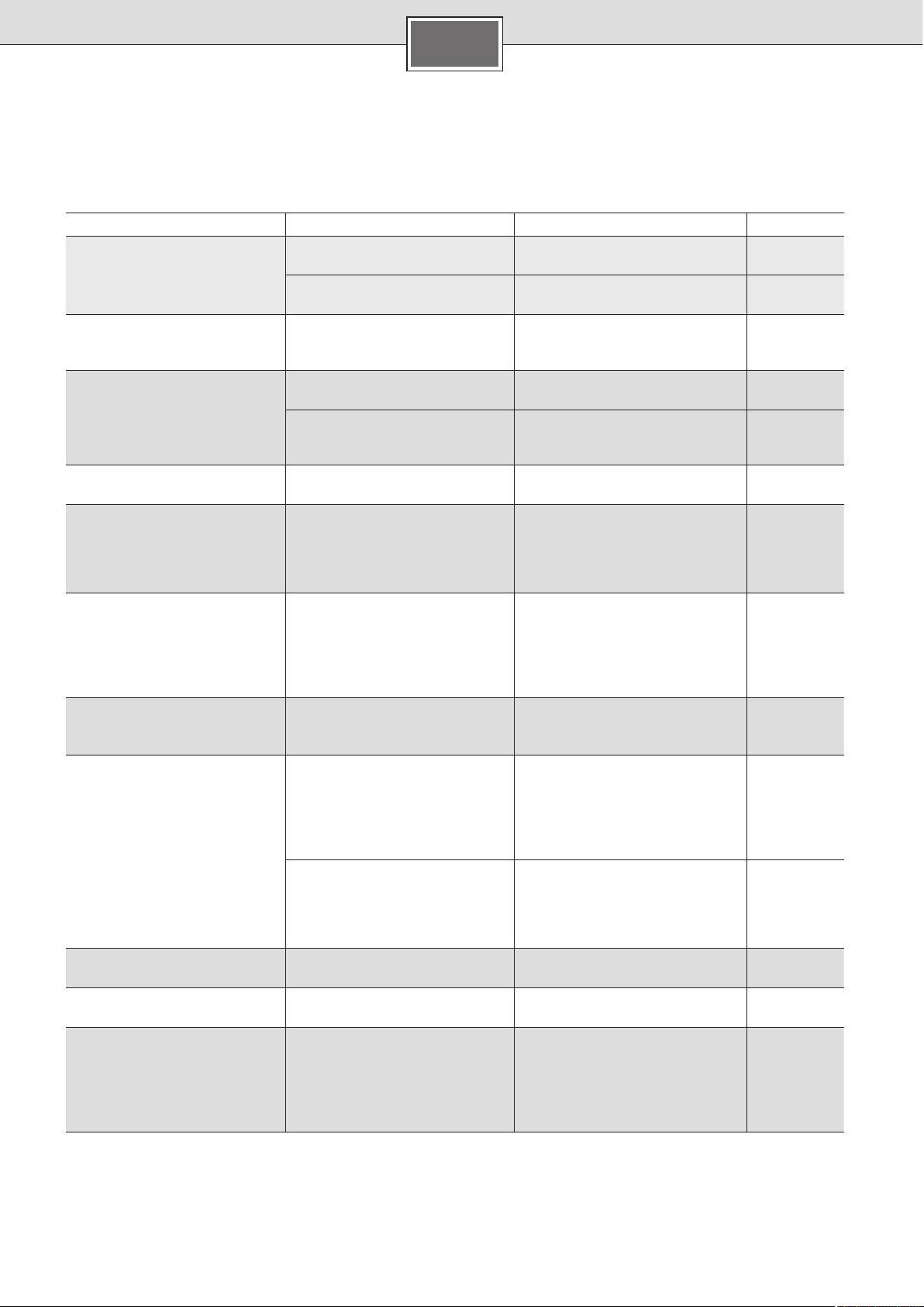
A fault, what to do?
If your appliance does not operate as required, it is often due to a very minor problem. Please check whether you can remedy
the fault yourself by using the following guidelines. You will save yourself the costs of an unnecessary visit by customer service
personnel.
Fault Cause Solution Who
Water flow-rate is too low. The filter in either the water tap or
Remove the filter and either
Customer
the showerhead is clogged.
clean it or descale it.
The filter in the corner regulating
Get a servicing expert to clean the
Servicing
valve is clogged.
filter.
expert
The desired water temperature is
The continuous-flow heater is
Set the temperature on the continu-
Customer
set, but it is not reached.
connected to a thermostatically-
ous-flow heater to “60 °C”.
controlled water faucet.
The display is blank The fuse in the house electrical in-
Check the fuse in the house electri-
Customer
stallation has triggered/blown.
cal installation.
The appliance's automatic circuit
Get the appliance's automatic
Servicing
breaker has been tripped.
circuit breaker checked by an
expert
electrician.
The water is not warm. The fuse in the house electrical in-
Check the fuse in the house electri-
Customer
stallation has tripped/blown.
cal installation.
From time to time, cold water
The air sensor in the appliance de-
After a few seconds, the continu-
Continuous-
flows out.
tects air in the water and momen-
ous-flow heater automatically goes
flow heater
tarily switches the heating element
back into operation.
automati-
off.
cally resolves
problem
The set temperature, for instance
The temperature of the water
The thermostatic premixer in the
Customer
41.0 °C flashes. The temperature
supplying the continuous-flow
domestic supply must be set ac-
of the water leaving the tap is
heater is higher than the set tem-
cordingly to lower temperatures.
higher than the set temperature.
perature (e. g. due to pre-warmed
water supplied from a solar water
heater).
Winter operation:The desired wa-
The supply temperature has
Reduce the water flow on the taps
Customer
ter temperature leaving the tap is
reduced.
until the desired water temperature
no longer reached.
is reached.
E02 No thermostatic premixer available
Install a thermostatic premixer in
Customer
The supply temperature to the
the domestic supply.
continuous-flow heater is higher
than 55 °C (e. g. due to pre-warmed
water supplied from a solar water
heater).
The supply temperature to the
The thermostatic premixer in the
continuous-flow heater is higher
domestic supply must be set ac-
than 55 °C (e. g. due to pre-warmed
cordingly to lower temperatures.
water supplied from a solar water
heater).
E03–E04 Temperature sensor defective Please contact customer service. Customer
Service
E05–E07 Electronic malfunction Please contact customer service. Customer
Service
E08 Frost damage
The appliance is defective! Switch
Customer/
The water supply sensor measures
off the water supply immediately
Servicing
a temperature on ≤ 0 °C.
and disconnect the appliance from
expert
the electrical supply (also refer to
the safety instructions)
Please contact customer service.
en
Disposal
Guarantee
The guarantee conditions for this appliance are as defined by
our representative in the country in which it is sold.
Details regarding these conditions can be obtained from the
dealer from whom the appliance was purchased. The bill of
sale or receipt must be produced when making any claim un-
der the terms of this guarantee.
Subject to change without notice.
13
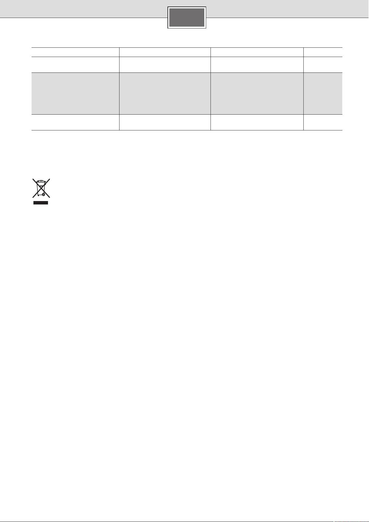
Fault Cause Solution Who
E09 Temperature sensor/
Please contact customer service. Customer
electronics defective
Service
E10–E11 Bubble detection triggers. Disconnect the appliance from the
Customer/
electrical supply.
Servicing
Open the warm water tap fully for
expert
venting purposes and flush out the
appliance thoroughly for 1 minute.
Switch the power back on again.
E12–E13 Electronic malfunction Please contact customer service. Customer
Service
If the fault could not be eliminated, please call customer service.
This appliance is labelled in accordance with Euro-
pean Directive 2012/19/EG concerning used elec-
trical and electronic appliances (waste electrical
and electronic equipment – WEEE).
The guideline determines the framework for the
return and recycling of used appliances as applica-
ble throughout the EU.
Please ask your specialist retailer about current
disposal facilities.
