Karcher KM 120/150 R P: Operating and Functional Elements
Operating and Functional Elements: Karcher KM 120/150 R P
-
4
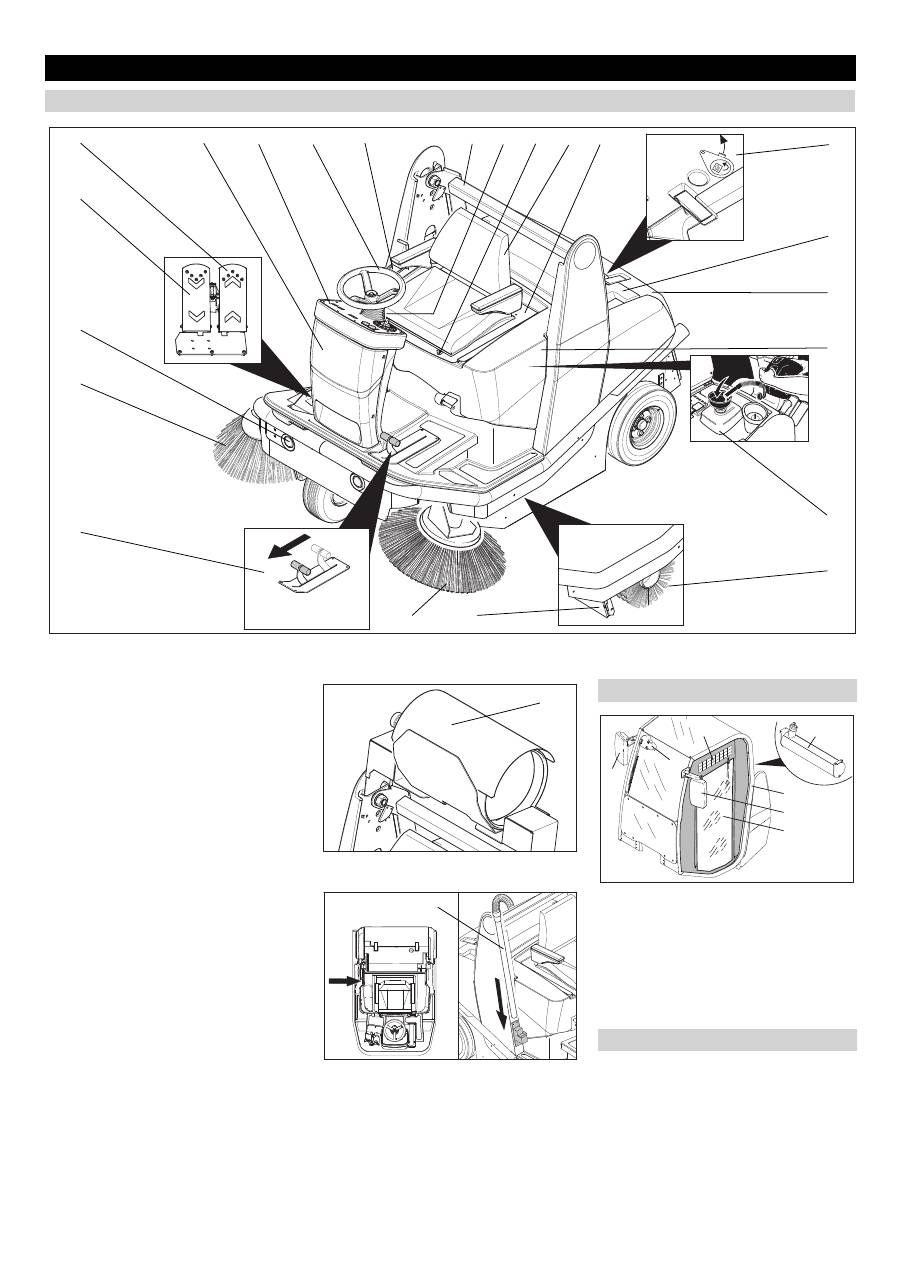
Figure 2a
1 Operator control unit for waste contain-
er and parking brake
2 Steering wheel
3 Operator console
4 Fuses (behind front panel)
5 Accelerator pedal, forwards
6 Accelerator pedal, reverse
7 Lights
8 Right side brush
9 Left side brush
10 Bulk waste flap
11 Pedal for raising/lowering bulk waste
flap
12 Lift/tilt emptying mechanism
13 Lever for steering wheel adjustment
14 Lever for seat adjustment
15 Seat (with seat contact mat)
16 Seat bracket
17 Wet/dry flap
18 Filter case
19 Waste container
20 Cover
21 Tank
22 Roller brush
23 Gas cylinder (only KM 120/150 R LPG)
24 Installation set suction hose (option)
Figure 2b
Figure 2c
Figure 2d
1 Driver cabin (optional)
2 Tank
3 Turn on/off the wipers
4 Right exterior mirror
5 Left exterior mirror
6 Plastic sheet doors
7 Ventilation slots
The operating elements for the cleaning
process are yellow.
The controls for the maintenance and
service are light gray.
Operating and Functional Elements
Machines without driver cabin
5 6 7 8 11 17 18 19 20 21 22 4 3 2 1 12 13 14 15 16 9 10 23 24
Machines with driver cabin
Colour coding
1 5 6 4 3 7 2 24 EN
-
5
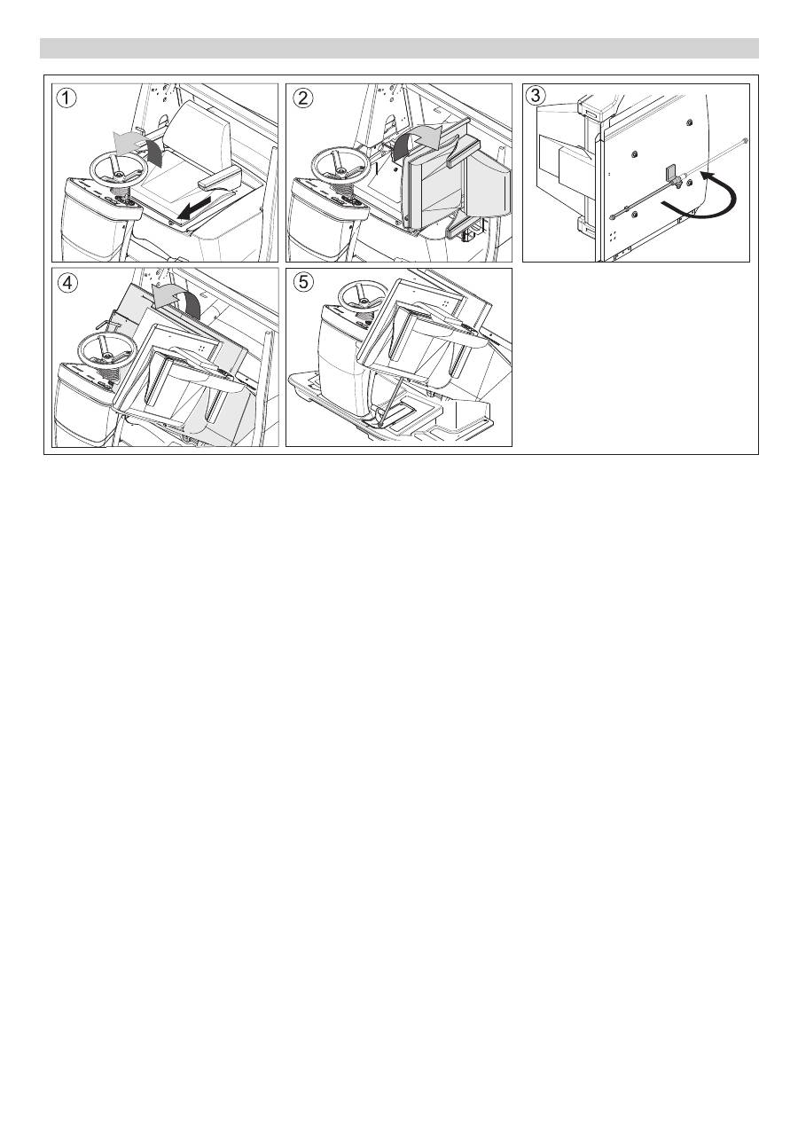
Figure 3
Danger
Risk of injury! When open, the cover must
be propped up using the retaining rod.
Figure 1
Operate steering wheel adjustment le-
ver and fold steering wheel forwards.
Operate seat adjustment lever and
slide seat forwards.
Figure 2
Fold seat bracket to the side.
Figure 3
Fold out retaining rod.
(only 120/150 KM without driver cabin)
Figure 4
Fold cover forwards.
Figure 5
Insert retaining rod into the recess next
to the bulk waste flap pedal.
(only 120/150 KM without driver cabin)
Follow this sequence in reverse order to
close the cover.
Opening/closing and securing cover
25 EN
-
6
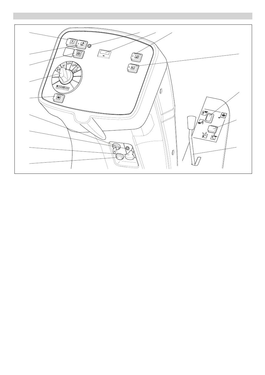
Figure 4
1 Programme switch
2 Switch two-hand operations Lift/tilt
emptying mechanism
3 Button for filter shaker system
4 Button for power-operating mode
5 Indicator lamp for power-operating
mode
6 Elapsed-time counter with reset button
7 Switch for working lamp
8 Horn switch
9 Raise/lower waste container
10 Tilt waste container outwards/inwards
11 Parking brake
12 Ignition lock
13 Charge indicator lamp (only KM 120/
150 R D and LPG)
14 Choke (only KM 120/150 R G)
15 Remote button (only KM 120/150 R
LPG)
16 Wet cleaning switch, installation set
suction hose (option)
Operator console
3 4 16 1 2 12 13 14 15 5 6 7 8 9 10 11 26 EN
Оглавление
- Inhaltsverzeichnis
- Funktion Bestimmungsgemäße Ver- wendung
- Bedien- und Funktionselemente
- Vor Inbetriebnahme
- Betrieb
- Stilllegung
- Transport Lagerung des Gerätes Pflege und Wartung
- Hilfe bei Störungen
- Technische Daten
- Zubehör
- Contents
- Function Proper use
- Operating and Functional Elements
- Before Startup
- Operation
- Shutdown
- Transport Storing the device Maintenance and care
- Troubleshooting
- Technical specifications
- Accessories
- Table des matières
- Fonction Utilisation conforme
- Eléments de commande et de fonction
- Avant la mise en service
- Fonctionnement
- Remisage
- Assistance en cas de panne
- Caractéristiques techniques
- Accessoires
- Indice
- Funzione Uso conforme a destinazione
- Elementi di comando e di funzione
- Prima della messa in funzione
- Funzionamento
- Fermo dell'impianto
- Guida alla risoluzione dei guasti
- Dati tecnici
- Accessori
- Inhoudsopgave
- Functie Reglementair gebruik
- Elementen voor de bediening en de functies
- Voor de inbedrijfstelling
- Werking
- Stillegging
- Hulp bij storingen
- Technische gegevens
- Toebehoren
- Índice de contenidos
- Función Uso previsto
- Elementos de operación y funcionamiento
- Antes de la puesta en marcha
- Funcionamiento
- Parada
- Ayuda en caso de avería
- Datos técnicos
- Accesorios
- Índice
- Funcionamento Utilização conforme o fim a que se destina a máquina
- Elementos de comando e de funcionamento
- Antes de colocar em funcio- namento
- Funcionamento
- Desactivação da máquina
- Ajuda em caso de avarias
- Dados técnicos
- Acessórios
- Indholdsfortegnelse
- Funktion Bestemmelsesmæssig an- vendelse
- Betjenings- og funktionselementer
- Inden ibrugtagning
- Drift
- Afbrydning/nedlæggelse
- Transport Opbevaring af maskinenPleje og vedligeholdelse
- Hjælp ved fejl
- Tekniske data
- Tilbehør
- Innholdsfortegnelse
- Funksjon Forskriftsmessig bruk
- Betjenings- og funksjonelementer
- Før den tas i bruk
- Drift
- Sette bort
- Transport Lagring av maskinen Pleie og vedlikehold
- Feilretting
- Tekniske data
- Tilbehør
- Innehållsförteckning
- Funktion Ändamålsenlig användning
- Manövrerings- och funktionselement
- Före ibruktagande
- Drift
- Nedstängning
- Transport Lagring av maskinen Skötsel och underhåll
- Åtgärder vid störningar
- Tekniska data
- Tillbehör
- Sisällysluettelo
- Toiminta Käyttötarkoitus
- Ohjaus- ja käyttölaitteet
- Ennen käyttöönottoa
- Käyttö
- Seisonta-aika
- Kuljetus Koneen säilytys Hoito ja huolto
- Häiriöapu
- Tekniset tiedot
- Tarvikkeet
- Πίνακας περιεχομένων
- Λειτουργία Χρήση σύμφωνα με τους κα - νονισμούς
- Προστασία περιβάλλοντος
- Στοιχεία χειρισμού και λειτουργίας
- Πριν τη θέση σε λειτουργία
- Λειτουργία
- Διακοπή της λειτουργίας
- Αποθήκευση της συσκευής Φροντίδα και συντήρηση
- Αντιμετώπιση βλαβών
- Τεχνικά χαρακτηριστικά
- Εξαρτήματα
- İ çindekiler
- Fonksiyon Kurallara uygun kullan ı m
- Kullan ı m ve çal ı ş ma elemanlar ı
- Cihaz ı çal ı ş t ı rmaya ba ş lama- dan önce
- Çal ı ş t ı rma
- Durdurma
- Ta ş ı ma Cihaz ı n depolanmas ı Koruma ve Bak ı m
- Ar ı zalarda yard ı m
- Teknik Bilgiler
- Aksesuar
- Оглавление
- Назначение Использование по назначе - нию
- Защита окружающей среды
- Описание элементов управления и рабочих узлов
- Перед началом работы
- Эксплуатация
- Вывод из эксплуатации
- Хранение прибора Уход и техническое обслу - живание
- Помощь в случае неполадок
- Технические данные
- Принадлежности
- Tartalomjegyzék
- Funkció Rendeltetésszer ű használat
- Kezelési- és funkciós elemek
- Üzembevétel el ő tt
- Üzem
- Leállítás
- Szállítás A készülék tárolása Ápolás és karbantartás
- Segítség üzemzavar esetén
- M ű szaki adatok
- Tartozékok
- Spis tre ś ci
- Funkcja U ż ytkowanie zgodne z prze- znaczeniem
- Elementy urz ą dzenia
- Przed pierwszym uruchomie- niem
- Dzia ł anie
- Wy łą czenie z eksploatacji
- Usuwanie usterek
- Dane techniczne
- Akcesoria


