Pioneer GM-6500F: Connecting the units
Connecting the units: Pioneer GM-6500F
Section
03
Connecting the units
Please see the following section for speaker
Connection diagram
connection instructions. Refer to Connections
when using the speaker input wire on page 9.
9 Speaker output terminals
Please see the following section for speaker
connection instructions. Refer to Connections
when using the speaker input wire on page 9.
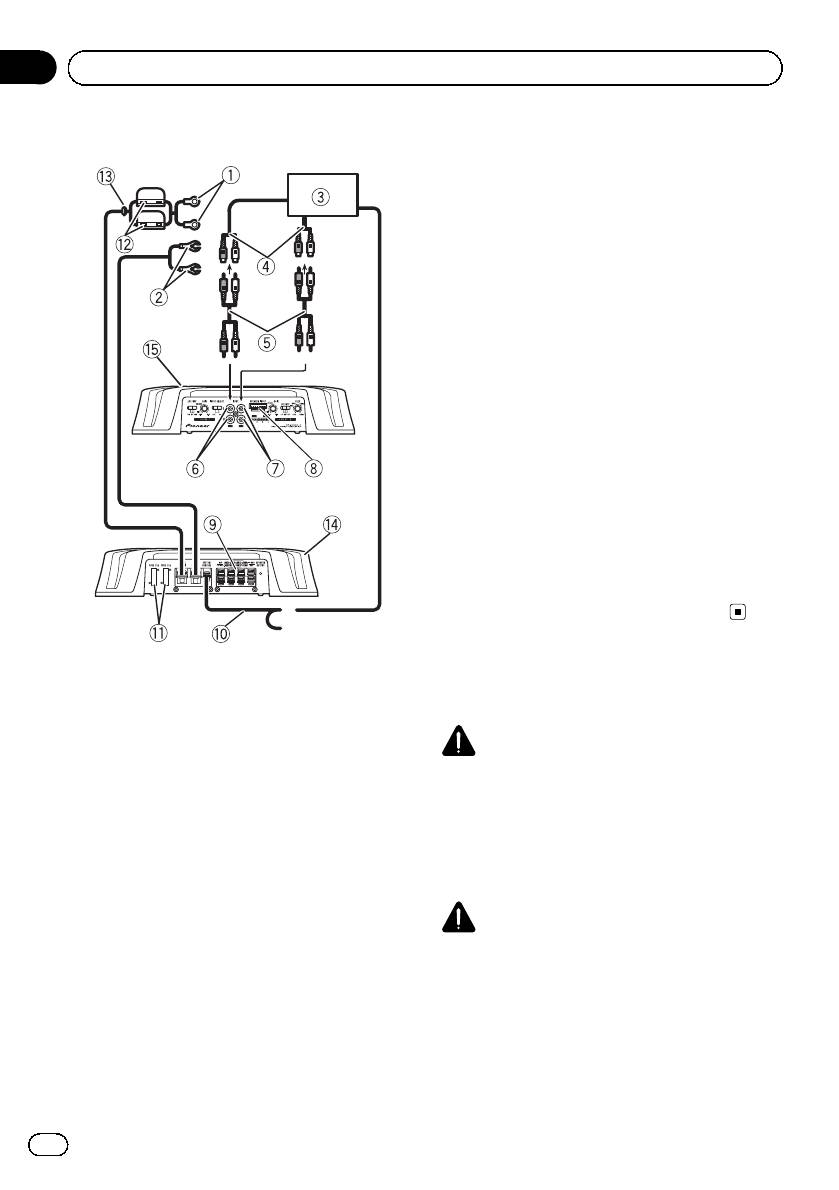
a System remote control wire (sold separately)
Connect male terminal of this wire to the sys-
tem remote control terminal of the car stereo.
The female terminal can be connected to the
auto-antenna relay control terminal. If the car
stereo lacks a system remote control terminal,
connect the male terminal to the power term-
inal via the ignition switch.
b Fuse (25 A) × 2
c Fuse (30 A) × 2
d Grommet
e Rear side
f Front side
Note
INPUT SELECT (input select) switch must be set.
For details, see Setting the unit on page 4.
1 Special red battery wire
Before connecting the
RD-223 (sold separately)
After completing all other amplifier connec-
amplifier
tions, finally connect the battery wire terminal
of the amplifier to the positive (+) battery
WARNING
terminal.
! Secure the wiring with cable clamps or adhe-
2 Ground wire (Black)
sive tape. To protect the wiring, wrap sections
RD-223 (sold separately)
in contact with metal parts in adhesive tape.
Connect to metal body or chassis.
! Never cut the insulation of the power supply
3 Car stereo with RCA output jacks (sold sepa-
to feed power to other equipment. Current ca-
rately)
pacity of the wire is limited.
4 External output
If only one input plug is used, do not connect
CAUTION
anything to RCA input jack B.
! Never shorten any wires, the protection circuit
5 Connecting wire with RCA pin plugs (sold se-
may malfunction.
parately)
! Never ground speaker wire directly or band to-
6 RCA input jack A
gether multiple speakers’ negative (*) lead
7 RCA input jack B
wires.
8 Speaker input terminal (use a connector in-
cluded)
6
En
Section
Connecting the units
03
English
! If the system remote control wire of the ampli-
About suitable
fier is connected to the power terminal via the
specification of speaker
ignition switch (12 V DC), the amplifier will re-
main on with the ignition whether the car
Ensure speakers conform to the following
stereo is on or off, which may exhaust battery
standards, otherwise there is a risk of fire,
if the engine is at rest or idling.
smoke or damage. Speaker impedance is 2 W
! Install and route the separately sold battery
to 8 W,or4W to 8 W for two-channel and other
wire as far as possible from the speaker wires.
bridge connections.
Install and route the separately sold battery
Subwoofer
wire, ground wire, speaker wires and the am-
plifier as far away as possible from the anten-
Speaker channel Power
na, antenna cable and tuner.
Nominal input:
Four-channel output
Min. 60 W
Nominal input:
About bridged mode
Two-channel output
Min. 180 W
Three-channel
Nominal input:
Speaker output A
Min. 60 W
Three-channel
Nominal input:
Speaker output B
Min. 180 W
Other than subwoofer
Speaker channel Power
Max. input:
Four-channel output
Min. 120 W
Max. input:
Speaker impedance is max. 4 W, please carefully
Two-channel output
Min. 360 W
check. Improper connection to the amplifier may
result in malfunction or personal injury due to
Three-channel
Max. input:
Speaker output A
Min. 120 W
burns from overheating.
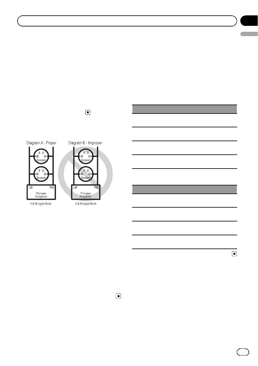
For bridged mode for a two-channel amplifier,
Three-channel
Max. input:
with a 4 W load, either wire two 8 W speakers in
Speaker output B
Min. 360 W
parallel, Left + and Right * (Diagram A) or use a
single 4 W speaker. For other amplifiers, please
follow the speaker output connection diagram for
bridging shown on rear: two 8 W speakers in par-
Connecting the speakers
allel for a 4 W load or a single 4 W speaker per
channel.
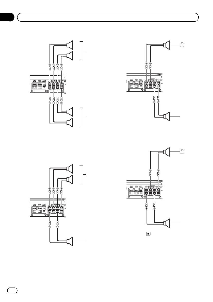
The speaker output mode can be four-channel,
For any further enquiries, contact your local
three-channel (stereo and mono) or two-chan-
authorized Pioneer dealer or customer service.
nel (stereo or mono). Connect the speaker
leads based on the mode and the figures
shown below.
7
En
Section
03
Connecting the units
Four-channel output
Two-channel output (Stereo)
1
3
2
2
4
2
1
1 Speaker (Right)
1 Right
2 Speaker (Left)
2 Left
Two-channel output (Mono)
3 Speaker out A
4 Speaker out B
Three-channel output
1
3
2
1
1 Speaker (Mono)
4
1 Right
Connections when using
2 Left
the RCA input jack
3 Speaker out A
Connect the car stereo RCA output jack and
4 Speaker out B (Mono)
the RCA input jack of the amplifier.
8
En
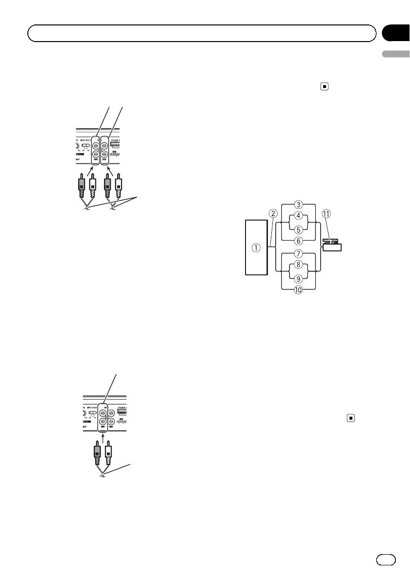
Four-channel / Three-channel output
! Slide INPUT SELECT (input select) switch
to 4CH position.
12
4
3
1 RCA input jack A
2 RCA input jack B
3 Connecting wires with RCA plugs (sold sepa-
rately)
4 From car stereo (RCA output)
If only one input plug is used, e.g. when the
car stereo has only one output (RCA output),
connect the plug to RCA input jack A rather
than B.
Two-channel output (Stereo) / (Mono)
! Slide INPUT SELECT (input select) switch
to 2CH position.
1
2
3
Section
Connecting the units
03
English
2 Connecting wire with RCA pin plugs (sold se-
parately)
3 From car stereo (RCA output)
Connections when using
the speaker input wire
Connect the car stereo speaker output wires
to the amplifier using the supplied speaker
input wire.
! Do not connect both the RCA input and the
speaker input at the same time.
1 Car Stereo
2 Speaker output
3 White/black: CH A, Left *
4 White: CH A, Left +
5 Gray/black: CH A, Right *
6 Gray: CH A, Right +
7 Green/black: CH B, Left *
8 Green: CH B, Left +
9 Violet/black: CH B, Right *
a Violet: CH B, Right +
b Speaker input connector
To speaker input terminal of this unit.
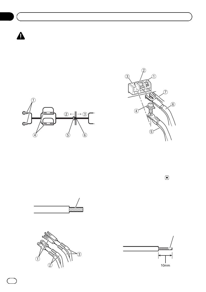
Connecting the power
terminal
The use of a special red battery and ground
wire RD-223, available separately, is recom-
1 RCA input jack A
mended. Connect the battery wire directly to
For two-channel output, connect the RCA
the car battery positive terminal + and the
plugs to the RCA input jack A.
ground wire to the car body.
9
En
Section
03
Connecting the units
1 Lug (sold separately)
WARNING
2 Battery wire
If the battery wire is not securely fixed to the term-
3 Ground wire
inal using the terminal screws, there is a risk of
overheating, malfunction and injury, including
4 Connect the wires to the terminal.
minor burns.
Fix the wires securely with the terminal
screws.
1 Route battery wire from engine com-
partment to the vehicle interior.
After completing all other amplifier connec-
tions, finally connect the battery wire terminal
of the amplifier to the positive (+) battery
terminal.
1 Positive (+) terminal
1 System remote control terminal
2 Engine compartment
2 Ground terminal
3 Vehicle interior
3 Power terminal
4 Fuse (30 A) × 2
4 Terminal screws
5 Insert the O-ring rubber grommet into the
5 Battery wire
vehicle body.
6 Ground wire
6 Drill a 14 mm hole into the vehicle body.
7 System remote control wire
2 Twist the battery wire, ground wire
and system remote control wire.
Twist
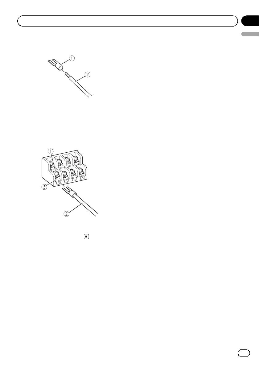
Connecting the speaker
output terminals
1 Use wire cutters or a utility knife to
strip the end of the speaker wires to ex-
pose about 10 mm of wire and then twist
3 Attach lugs to wire ends.
the wire.
Use pliers, etc., to crimp lugs to wires.
Twist
10
En
Section
Connecting the units
03
English
2 Attach lugs to wire ends.
Use pliers, etc., to crimp lugs to wires.
1 Lug (sold separately)
2 Speaker wire
3 Connect the speaker wires to the
speaker output terminals.
Fix the speaker wires securely with the term-
inal screws.
1 Terminal screws
2 Speaker wires
3 Speaker output terminals
11
En
Оглавление
- Before you start
- Setting the unit
- Connecting the units
- Installation
- Additional information
- Avant de commencer
- Réglage de l’appareil
- Connexion des appareils
- Connexions lors de l’utilisation du jack d’entrée RCA
- Connexion des appareils
- Installation
- Informations complémentaires
- Prima di iniziare
- Impostazione dell’unità
- Collegamento delle unità
- Collegamenti utilizzando un connettore di ingresso RCA
- Collegamento delle unità
- Installazione
- Informazioni supplementari
- Antes de comenzar Visite nuestro sitio Web
- Antes de comenzar
- Configuración de la unidad
- Conexión de las unidades
- Conexiones al utilizar una toma de entrada RCA
- Conexión de las unidades
- Instalación
- Información adicional
- Bevor Sie beginnen
- Einstellen des geräts
- Anschließen der Geräte
- Anschlüsse bei Verwendung des Cinch-Eingangs
- Anschließen der Geräte
- Installation
- Zusätzliche Informationen
- Vóór u begint
- Het toestel installeren
- De toestellen aansluiten
- Aansluiting via de RCA-ingang
- De toestellen aansluiten
- Installatie
- Aanvullende informatie
- Перед началом эксплуатации
- Настройка усилителя
- Подключение устройств
- Подключение устройств Перед подключением Режим мостового соединения усилителя
- Подключение устройств
- Подключение с использованием входного гнезда RCA
- Подключение устройств
- Установка
- Дополнительная информация


