Karcher HD 9-18-4 ST: Installing the plant
Installing the plant: Karcher HD 9-18-4 ST
-
13
– Check the contents of the pack before
unpacking.
– In case of transport damage inform ven-
dor immediately
– Store the drilling template on the carton
to assemble the device.
Note:
The water connection, the high pressure
network as well as the electrical connection
can only be carried out by authorised ex-
perts in accordance with local regulations.
– The installion should be set-up in a dry,
non-explosive environment.
– The installion should be installed on
firm and even ground.
– The installion should be easily accessi-
ble for maintenance work.
The following are required for installation:
– Wall mount
– Installation with the mounting kit floor
rack (optional)
몇
CAUTION
Risk of personal injury or damage! Note the
weight of the appliance during installation.
ATTENTION
Risk of damage! Freezing water in the ap-
pliance can destroy parts of the appliance.
The machine should be stored in frost-free
rooms. In case there is frosting risk, for e.g.
if the machine is installed in open areas,
then the machine must first be emptied and
flushed using an anti-freezing agent.
Check the wall's support capacity.
Mark the wall using the drill template on
the packaging.
Drill the bores into the wall.
Attach the installation materials to the
wall.
Remove the appliance cover.
Hang up the appliance and secure it
against falling down.
Replace the appliance hood and fasten
it with screws.
– For connection values, see technical
data and type plate.
– The power supply designed for operat-
ing the plant must be suitable for contin-
uous operations.
– The electrical connections must be
done by an electrician according to IEC
60364-1.
– Current-carrying parts, cables and ap-
pliances in the working area must be in-
stalled in a defectless state and must be
protected against water sprays.
– Design the water supply for continuous
operations.
– The water feed line is provided with a
stop valve and can be moved over a
pressure hose and attached to the high
pressure system.
– If the cross section of the line is too
small or if the advance pressure is too
low, there will be a lack of water.
– When the advance pressure or the
rinse pressure is too high, it is absolute-
ly necesary to install a pressure reduc-
er.
– A water drain must be present at instal-
lation site.
For installation, please follow the specifica-
tions of the VDMA sheet 24416 "High pres-
sure cleaners; fixed high pressure cleaning
systems; concepts, requirements, installa-
tion, testing" (the German version can be
procured from Beuth Verlag, Cologne,
www.beuth.de).
– The fixed pipe network and the install-
ion should be connected with a high
pressure line.
– The fixed pipe network should be
placed as straight as possible. High
pressure piping systems should be in-
stalled correctly with removable and
fixed clips, taking into consideration the
variation in length caused by the effects
of heat and pressure.
– In order to keep pressure losses in the
high pressure piping as small as possi-
ble, we recommend the following:
Pipelines: Nominal width DN 15 (1/2“).
Hose lines: Nominal width DN 8.
In regards to the above mentioned stand-
ard values, the length of the pipes and the
number of direction changes and fittings
must be taken into account.
Illustration, see "Operating components".
Mount the nozzle on the spray lance
(markings on the adjustment ring at the
top).
Connect spray lance to trigger gun.
Lever out the safety clip of the hand
spray gun using a screw-driver (Picture
A).
Place the hand-spray gun upside down
and insert the end of the high pressure
hose till the end. Ensure that the lose
disc falls right below on the hose end
(Picture B).
Press the safety clip back into the hand-
spray gun. The hose can be pulled out
max. 1 mm if it has been installed cor-
rectly. Otherwise, it means the disc has
been installed wrongly (picture C).
Connect the high pressure hose to the
high pressure outlet of the appliance or
the high pressure pipe network.
The detergent tank is set up in such a way,
that the bottom of the tank is located not
more than 1.5 m unter the unit.
Check that water inlet has the required
flow and the permissible temperature.
Check oil level of the pump.
Cut off tip of oil container.
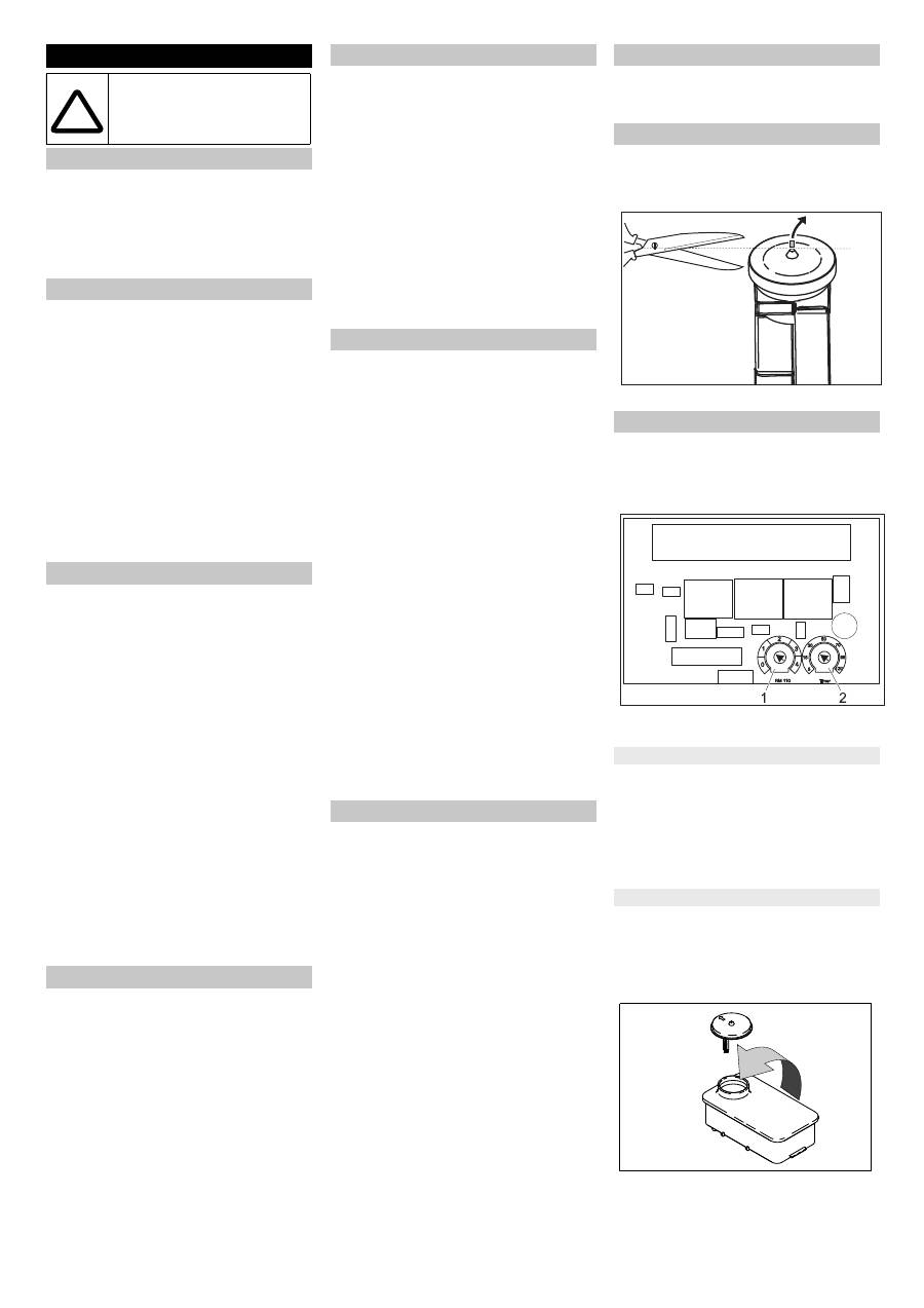
Adjustments are made on the control circuit
board
The control circuit board is located in the
electric box of the high pressure pump.
1 Potentiometer water hardness
2 Potentiometer readiness time period
Initiate the stand by-period with the po-
tentiomenter on the electronic control.
Adjustment by the manufacturer:
10 Minutes
The time can be set between 5 and 120
minutes. A simple scale of standard values
is printed on the control board.
Use hard water for hot water operation to
protect against calcification In addition add
water softener to the water. The dispensing
flow can be adjusted to the degree of water
hardness.
Fill the tank with Kaercher softener liq-
uid RM 110 (Order no. 2.780-001).
Determining the hardness of tap water:
– through the public water supply works,
Installing the plant
Only for authorised techni-
cians!
Unpacking
Installation
Fasten the device to the wall
Electrical connection
!
Water supply
High pressure installation
Attaching the Accessories
Install the detergent tank
Initial startup
Settings
Operational readiness period
Installation water softener (optional)
30
EN
Оглавление
- Inhaltsverzeichnis
- Bestimmungsgemäße Verwendung
- Funktion
- Geräteelemente
- Transport Lagerung des Gerätes Pflege und Wartung
- Hilfe bei Störungen
- Technische Daten
- Zubehör
- Anlageninstallation
- EG-Konformitätserklärung
- Kundendienst
- Contents
- Proper use
- Function
- Device elements
- Transport Storing the device Maintenance and care
- Troubleshooting
- Technical specifications
- Accessories
- Installing the plant
- EC Declaration of Conformity
- Customer Service
- Πίνακας περιεχομένων
- Χρήση σύμφωνα με τους κανονισμούς
- Λειτουργία
- Στοιχεία συσκευής
- Μεταφορά Αποθήκευση της συσκευής Φροντίδα και συντήρηση
- Αντιμετώπιση βλαβών
- Τεχνικά χαρακτηριστικά
- Εξαρτήματα
- Εγκατάσταση μονάδας
- Δήλωση Συμμόρφωσης των Ε . Κ .
- Υπηρεσία εξυπηρέτησης πελατών
- İ çindekiler
- Kurallara uygun kullan ı m
- Fonksiyon
- Cihaz elemanlar ı
- Ta ş ı ma Cihaz ı n depolanmas ı Koruma ve Bak ı m
- Ar ı zalarda yard ı m
- Teknik Bilgiler
- Aksesuar
- Sistem tesisat ı
- AB uygunluk bildirisi
- Mü ş teri hizmeti
- Оглавление
- Использование по назначению
- Назначение
- Элементы прибора
- Транспортировка Хранение прибора
- Уход и техническое обслуживание
- Помощь в случае неполадок
- Технические данные
- Принадлежности
- Инсталляция оборудования
- Заявление о соответствии ЕС
- Сервисная служба
- Spis tre ś ci
- U ż ytkowanie zgodne z przeznaczeniem
- Funkcja
- Elementy urz ą dzenia
- Transport Przechowywanie urz ą dzenia Czyszczenie i konserwacja
- Usuwanie usterek
- Dane techniczne
- Akcesoria
- Instalacja urz ą dzenia
- Deklaracja zgodno ś ci UE
- Serwis firmy
- Sisukord
- Sihipärane kasutamine
- Funktsioon
- Seadme elemendid
- Transport Seadme ladustamine Korrashoid ja tehnohooldus
- Abi häirete korral
- Tehnilised andmed
- Tarvikud
- Seadme installeerimine
- EÜ vastavusdeklaratsioon
- Klienditeenindus
- Satura r ā d ī t ā js
- Noteikumiem atbilstoša lietošana
- Darb ī ba
- Apar ā ta elementi
- Transport ē šana Apar ā ta uzglab ā šana Kopšana un tehnisk ā apkope
- Pal ī dz ī ba darb ī bas trauc ē jumu gad ī jum ā
- Tehniskie dati
- Piederumi
- Iek ā rtas instal ā cija
- EK Atbilst ī bas deklar ā cija
- Klientu apkalpošanas dienests
- Turinys
- Naudojimas pagal paskirt į
- Veikimas
- Prietaiso dalys
- Transportavimas Į renginio laikymas Prieži ū ra ir aptarnavimas
- Pagalba gedim ų atveju
- Techniniai duomenys
- Dalys
- Prietaiso į rengimas
- EB atitikties deklaracija
- Klient ų aptarnavimo tarnyba
- Зміст
- Правильне застосування
- Призначення
- Елементи приладу
- Транспортування Зберігання пристрою Догляд та технічне обслуговування
- Допомога у випадку неполадок
- Технічні характеристики
- Аксесуари
- Монтаж обладнання
- Заява при відповідність Європейського співтовариства
- Служба підтримки користувачів
