Pioneer DEH-P8100BT: Connecting the units
Connecting the units: Pioneer DEH-P8100BT

Connecting the units
English
• Control signal is output through blue/white cable
when this unit is powered on. Connect it to an
external power amp’s system remote control or
the vehicle’s auto-antenna relay control terminal
(max. 300 mA, 12 V DC). If the vehicle is equipped
with a glass antenna, connect it to the antenna
booster power supply terminal.
• Never connect blue/white cable to external power
amp’s power terminal. Also, never connect
it to the power terminal of the auto antenna.
Otherwise, battery drain or malfunction may
result.
• IP-BUS connectors are color-coded. Be sure to
connect connectors of the same color.
• Black cable is ground. This cable and other
product’s ground cable (especially, high-current
products such as power amp) must be wired
separately. Otherwise, fire or malfunction may
result if they are accidentally detached.
3
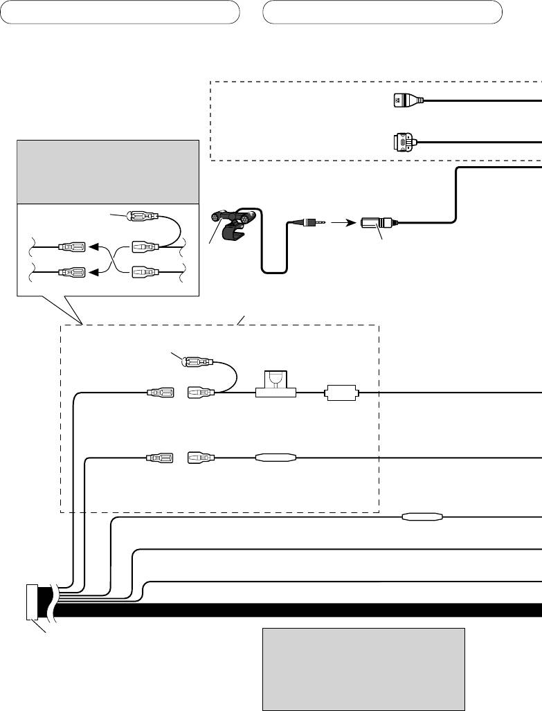
Connecting the units
Connecting the power cord
USB cable
Use supplied USB cable or separately
sold USB cable (CD-U150E).
iPod to USB connection cable
Use separately sold iPod to USB
Note
connection cable (CD-IU50).
Depending on the kind of vehicle,
the function of 3* and 5* may be
different. In this case, be sure to
connect 2* to 5* and 4* to 3*.
1*
15 cm
3* 2*
Microphone input
Microphone
4 m
4*5*
Connect leads of the same
color to each other.
Cap (1*)
Do not remove cap if
this terminal is not in
Fuse (10 A)
use.
Yellow (3*)
Yellow (2*)
Back-up (or
Connect to the constant 12 V
accessory)
supply terminal.
Fuse resister
Red (5*)
Red (4*)
Accessory (or
Connect to terminal controlled by
back-up)
ignition switch (12 V DC).
Fuse resister
Orange/white
Connect to lighting switch terminal.
Black (chassis ground)
Connect to a clean, paint-free metal location.
ISO connector
Note
Note
When using a subwoofer of 70 W (2
In some vehicles, the ISO connector may
Ω), be sure to connect with Violet
be divided into two. In this case, be sure to
and Violet/black leads of this unit.
connect to both connectors.
Do not connect anything with Green
and Green/black leads.
4
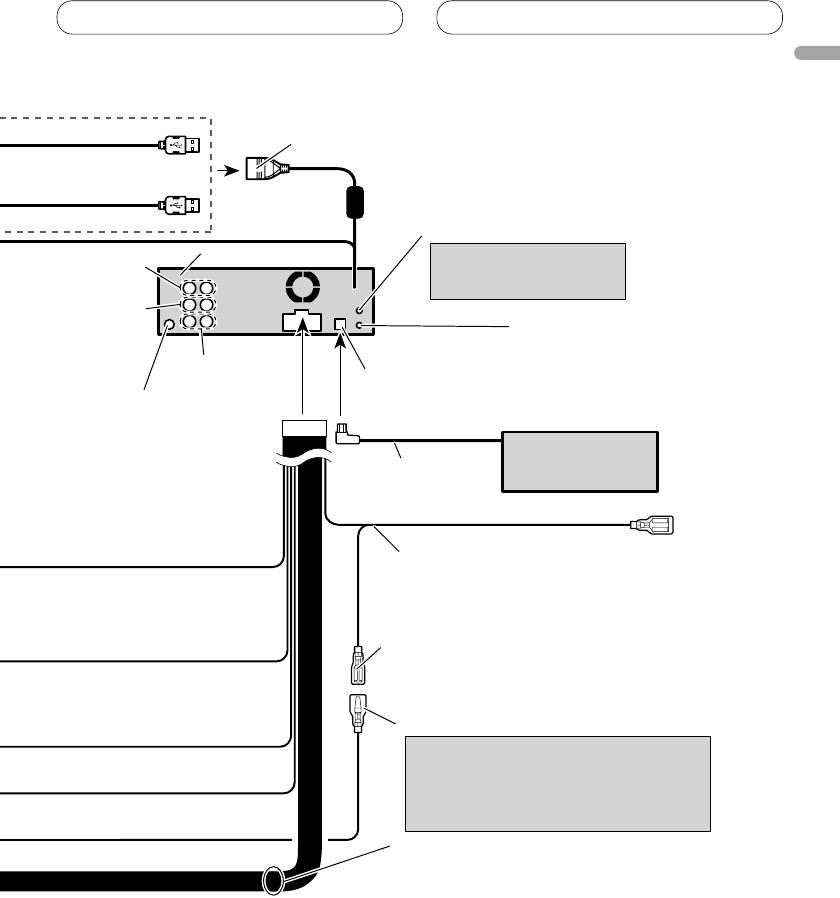
Connecting the units
English
1.5 m
USB1/USB2 input jack
20 cm
50 cm
AUX jack (3.5 φ)
Use a stereo mini plug cable
This product
Rear output
to connect with auxiliary
device.
Front output
Wired remote input
Hard-wired remote control
adaptor can be connected
Subwoofer output
(sold separately).
IP-BUS input (Blue)
Antenna jack
Multi-CD player
(sold separately)
IP-BUS cable
Blue/white
Connect to system control terminal of the
power amp (max. 300 mA 12 V DC).
Blue/white (7*)
Connect to auto-antenna relay control
terminal (max. 300 mA 12 V DC).
Blue/white (6*)
The pin position of the ISO connector will
differ depends on the type of vehicle.
Connect 6* and 7* when Pin 5 is an
antenna control type. In another type of
vehicle, never connect 6* and 7*.
Speaker leads
White: Front left
White/black: Front left
Gray: Front right
Gray/black: Front right
Green: Rear left or subwoofer
Green/black: Rear left or subwoofer
Violet: Rear right or subwoofer
Violet/black: Rear right or subwoofer
5
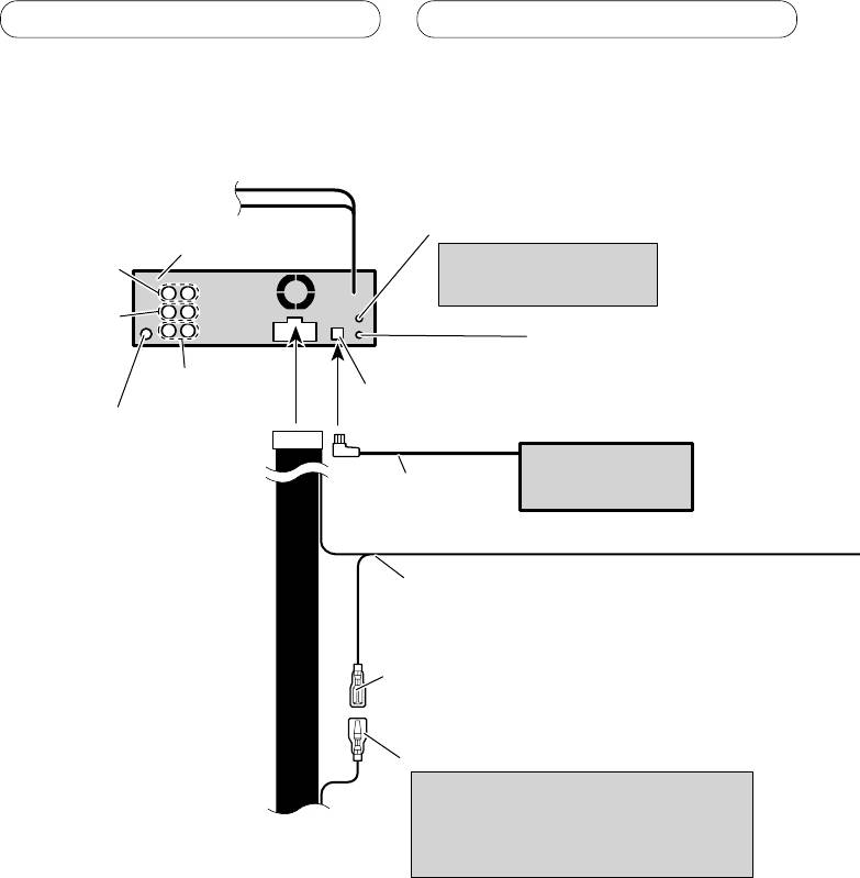
Connecting the units
When connecting to separately sold power amp
AUX jack (3.5 φ)
This product
Use a stereo mini plug cable
Rear output
to connect with auxiliary
device.
Front output
Wired remote input
Hard-wired remote control
adaptor can be connected
Subwoofer output
(sold separately).
IP-BUS input (Blue)
Antenna jack
Multi-CD player
(sold separately)
IP-BUS cable
Blue/white
Connect to system control terminal of the
power amp (max. 300 mA 12 V DC).
Blue/white (7*)
Connect to auto-antenna relay control
terminal (max. 300 mA 12 V DC).
Blue/white (6*)
The pin position of the ISO connector will
differ depends on the type of vehicle.
Connect 6* and 7* when Pin 5 is an
antenna control type. In another type of
vehicle, never connect 6* and 7*.
6
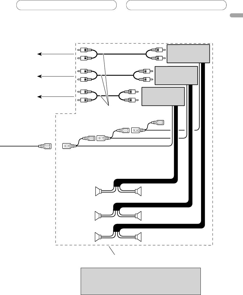
Connecting the units
English
Power amp
(sold separately)
To rear output
Power amp
(sold separately)
To front output
Power amp
(sold separately)
To subwoofer output
Connect with RCA cables
(sold separately)
System remote control
RightLeft
Subwoofer
Subwoofer
Front speaker Front speaker
Rear speaker Rear speaker
Perform these connections when using
the optional amplifier.
Note
Change the initial setting of this unit (refer to the
operation manual). The subwoofer output of this unit
is monaural.
7
Оглавление
- Contents Connecting the units
- Connecting the units
- Installation
- Contenido Conexión de las unidades
- Conexión de las unidades
- Instalación
- Inhalt Anschließen der Geräte
- Anschließen der Geräte
- Einbau
- Table des matières Connexions des appareils
- Connexions des appareils
- Installation
- Indice Collegamento delle unità
- Collegamento delle unità
- Installazione
- Inhoud Aansluiten van de toestellen
- Aansluiten van de toestellen
- Installatie
- Содержание Подключение устройств
- Подключение устройств
- Установка
