Karcher KM 120/150 R P 2SB: Transport Storing the device Maintenance and care
Transport Storing the device Maintenance and care: Karcher KM 120/150 R P 2SB
-
10
Only KM 120/150 R G and R LPG: Un-
screw spark plugs and pour approx.
3 cm³ of oil into the spark plug hole.
Crank the engine several times before
replacing the spark plug. Screw in the
spark plug.
Secure sweeper to prevent it rolling
away, lock parking brake.
Clean the inside and outside of the
sweeper.
Park the machine in a safe and dry
place.
Disconnect battery.
Charge battery approx. every 2 months.
Open cover and secure it (Diag. 3).
KM 120/150 R G:
Push lever in "OFF" direction.
KM 120/150 R D:
Turn lever to position "S".
Close cover.
Close gas drawing valve by turning it in
clock-wise direction.
CAUTION
Risk of injury and damage! Observe the
weight of the appliance when you transport
it.
몇
Warning
In general, when shipping the machine, the
freewheel lever must be engaged in the up-
per hole. Only once this has been done, will
the travel drive be ready for operation. The
machine must always be moved up or
down slopes by engaging self-propulsion.
Turn ignition key to "0" and remove it.
Only KM 120/150 R G and R D: Empty
tank. Draw off fuel using suitable pump.
Only KM 120/150 R LPG: Close the gas
cylinder valve and remove the cylinder.
Store the gas cylinder according to the
safety regulations for LPG vehicles.
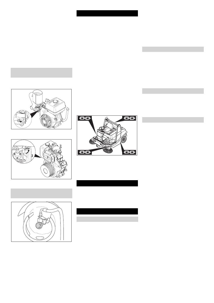
Secure the wheels of the machine with
wheel chocks.
Secure the machine with tensioning
straps or cables.
Lock parking brake.
Note
Observe markings for fixing points on base
frame (chain symbols). When loading or
unloading the machine, it may only be op-
erated on gradients of max. 18%.
CAUTION
Risk of injury and damage! Note the weight
of the appliance in case of storage.
Park the machine in a safe and dry place.
First switch off the appliance and re-
move the ignition key before performing
any cleaning or maintenance tasks on
the appliance, replacing parts or switch-
ing over to another function.
Pull out the battery plug or clamp the
battery while working on the electrical
unit.
–
Maintenance work may only be carried
out by approved customer service out-
lets or experts in this field who are famil-
iar with the respective safety
regulations.
–
Mobile appliances used for commercial
purposes are subject to safety inspec-
tions according to VDE 0701.
–
Use only roller brushes/ side-brushes
that are provided with the appliance or
specified in the Operations Manual.
The use of other roller brushes/ side-
brushes can affect the safety of the ap-
pliance.
–
Do not clean the appliance with a water
hose or high-pressure water jet (danger
of short circuits or other damage).
Danger
Risk of injury! Wear dust mask and protec-
tive goggles.
Open cover and secure it (Diag. 3).
Clean machine with a cloth.
Blow through machine with com-
pressed air.
Close cover.
Clean the machine with a damp cloth
which has been soaked in mild deter-
gent.
Note
Do not use aggressive cleaning agents.
Note
The elapsed-time counter shows the timing
of the maintenance intervals.
Daily maintenance:
Check engine oil level.
Check axle drive oil level.
Check tyre pressure.
Only KM 120/150 R LPG: Check gas
pipes and connecting screws.
Only KM 120/150 R LPG: Check gas fil-
ter in the screw to the gas cylinder to
see if it is dirty, clean it if required (every
time you change the cylinder).
Check function of all operator control el-
ements.
Weekly maintenance:
Check leakiness of fuel or gas connec-
tions.
Check return-line filter for sweeping
system.
Check air filter.
Check oil level of sweeper hydraulics.
Check hydraulic lines for leaks.
Check moving parts for freedom of
movement.
Check the sealing strips in the sweep-
ing area for position and wear.
Maintenance to be carried out every 100
operating hours:
Check leakiness of fuel or gas connec-
tions.
Change engine oil (initial change after
20 operating hours).
Only KM 120/150 R G and R LPG:
Check spark plug.
Check function of seat contact mat.
Check battery acid level.
Close fuel tap (only KM 120/150 R G
and R D)
Close gas supply (only KM 120/150
R LPG)
Transport Storing the device Maintenance and care
General notes
Cleaning the inside of the machine
External cleaning of the appliance
Maintenance intervals
Maintenance by the customer
30 EN
-
11
Check tension, wear and function of
drive belts (V-belt and circular belt).
Maintenance following wear:
Replace sealing strips.
Replace roller brush.
Replace side brush.
For description, see section on Mainte-
nance work.
Note
Where maintenance is carried out by the
customer, all service and maintenance
work must be undertaken by a qualified
specialist. If required, a specialised Kärch-
er dealer may be contacted at any time.
Maintenance to be carried out after 20 op-
erating hours:
Carry out initial inspection.
Maintenance to be carried out every 100
operating hours
Maintenance to be carried out every 200
operating hours
Maintenance to be carried out every 300
operating hours
Note
In order to safeguard warranty claims, all
service and maintenance work during the
warranty period must be carried out by the
authorised Kärcher Customer Service in
accordance with the maintenance booklet.
Preparation:
Park the sweeper on an even surface.
Turn ignition key to "0" and remove it.
Lock parking brake.
Danger
Risk of injury! While working around the lift/
tilt emptying mechanism, raise the waste
container to its highest point and secure.
Insert safety support into the piston rod
for the lifting cylinder and secure it.
Danger
Risk of injury due to engine overrun. Once
the engine has been switched off, wait for 5
seconds. Stay well clear of the working
area for this time.
Allow the machine sufficient time to cool
down before carrying out any mainte-
nance and repair work.
Do not touch any hot parts, such as the
drive motor and exhaust system.
Please observe the following warning notes
when handling batteries:
Danger
Risk of explosion! Do not put tools or similar
on the battery, i.e. on the terminal poles
and cell connectors.
Danger
Risk of injury! Ensure that wounds never
come into contact with lead. Always clean
your hands after having worked with batter-
ies.
Open cover and secure it (Diag. 3).
Insert battery in battery mount.
Screw on mounts on battery base.
Connect pole terminal (red cable) to
positive pole (+).
Connect pole terminal to negative pole
(-).
Danger
Risk of injury! Comply with safety regula-
tions on the handling of batteries. Observe
the directions provided by the manufacturer
of the charger.
Disconnect battery.
Connect positive terminal cable from
the charger to the positive pole connec-
tion on the battery.
Connect negative terminal cable from
the charger to the negative pole con-
nection on the battery.
Plug in mains connector and switch on
charger.
Charge battery using lowest possible
level of charging current.
몇
Warning
Regularly check the fluid level in acid-filled
batteries.
Unscrew all cell caps.
Where fluid level is too low, top up cells
to the mark provided with distilled wa-
ter.
Charge battery.
Screw in cell caps.
Note
Before removing the battery, make sure
that the negative pole lead is disconnected.
Check that the battery pole and pole termi-
nals are adequately protected with pole
grease.
Open cover and secure it (Diag. 3).
Disconnect battery.
Remove the battery from the battery
holder.
Dispose of the used battery according
to the local provisions.
Note
After the machine is switched on, the num-
ber of operating hours is displayed for 10
seconds. The fuel gauge is then automati-
cally displayed.
Note
The fuel gauge shows the length of time the
machine has been in operation since the
elapsed-time counter was last reset.
Note
The machine can be operated for a maxi-
mum of 3 hours on a full tank.
Check fuel gauge for elapsed-time
counter.
Maintenance by Customer Service
Maintenance Works
General notes on safety
Please do not release engine
oil, fuel oil, diesel and petrol
into the environment. Protect
the ground and dispose of
used oil in an environmentally-
clean manner.
Safety notes regarding the batteries
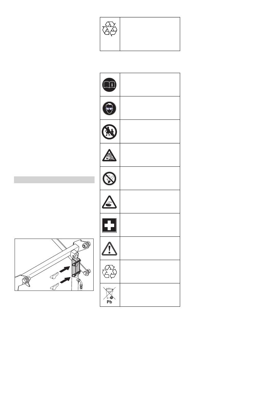
Observe the directions on the
battery, in the instructions for
use and in the vehicle operat-
ing instructions!
Wear an eye shield!
Keep away children from acid
and batteries!
Risk of explosion!
Fire, sparks, open light, and
smoking not allowed!
Danger of causticization!
First aid!
Warning note!
Disposal!
Do not throw the battery in the
dustbin!
Installing and connecting the battery
Charging battery
Check fluid level in the battery and ad-
just if required
Remove the battery
Check fuel indicator (only KM 120/150
R G and R D)
31 EN
-
12
Check gas filter in the screw to gas cyl-
inder to see if it is dirty.
Clean dirty filters with compressed air.
Note
Inspection must be carried out by a quali-
fied specialist.
Check gas connections, pipes and
evaporators using leak-search spray for
leaks.
Note
Leaks in the gas cylinder cause formation
of crusts or yellow frothy deposits on the
gas connections, pipes and evaporator.
Contact Kärcher Customer Service for
maintenance of the gas unit.
Park the sweeper on an even surface.
Connect air pressure testing device to
tyre valve.
Check air pressure and adjust if re-
quired.
Set air pressure for the front and rear
tyres at 6 bar.
Danger
Risk of injury!
Park the sweeper on an even surface.
Remove ignition key.
When carrying out repairs on public
highways, wear warning clothing when
working close to passing traffic.
Check stability of ground. Also secure
the machine with wheel chock(s) to pre-
vent it rolling away.
Lock parking brake.
Check tyres
Check tyre contact face for foreign ob-
jects.
Remove objects found.
Use suitable, commercially available
materials to carry out tyre repairs.
Note
Observe the manufacturer's recommenda-
tions. The journey may be resumed provid-
ing that the directions supplied by the
product manufacturer have been observed.
The tyre/wheel change should nonetheless
be carried out as soon as possible.
Open quick-release locks on the rele-
vant side panel.
Remove side panel.
Loosen wheel nuts.
Position vehicle jack at the appropriate
mounting point for the front or rear
wheel.
Raise machine using vehicle jack.
Remove wheel nuts.
Remove wheel.
Mount spare wheel.
Screw on wheel nuts.
Lower machine using vehicle jack.
Tighten wheel nuts.
Screw on side panel.
Note
Use a suitable commercially available vehi-
cle jack.
몇
Warning (only KM 120/150 R G and R
LPG)
The engine is equipped with an oil deficien-
cy switch. When the fill level is insufficient,
the engine switches off and can only be re-
started once the engine oil has been re-
plenished.
Danger
Risk of burns!
Allow engine to cool down.
Wait for at least 5 minutes after switch-
ing off the engine before checking the
engine oil fill level.
Open cover and secure it (Diag. 3).
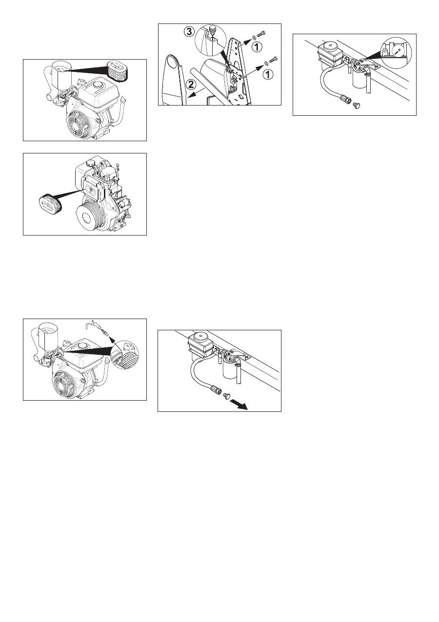
KM 120/150 R G and R LPG:
KM 120/150 R D:
Pull out oil dipstick.
Wipe off oil dipstick and insert.
Pull out oil dipstick.
Note
Oil must be present on at least one third of
the oil dipstick. If the oil level is less than
this, top up engine oil until it reaches the
lower edge of the filler opening.
Only KM 120/150 R G and R LPG: Dis-
mantle the extension piece at the oil fill-
er opening.
Top up engine oil using 6.491-538 oil-
change pump.
Only KM 120/150 R G and R LPG: In-
stall the extension piece at the oil filler
opening.
Close oil filler opening.
Wait at least 5 minutes.
Check engine oil level.
Oil grade: see Technical Data
Pull out oil dipstick.
Only KM 120/150 R G and R LPG: Dis-
mantle the extension piece at the oil fill-
er opening.
Suck off engine oil using 6.491-538 oil-
change pump.
Fill in new engine oil using 6.491-538
oil-change pump.
Oil grade: see Technical Data
Only KM 120/150 R G and R LPG: In-
stall the extension piece at the oil filler
opening.
Close oil filler opening.
Wait at least 5 minutes.
Check engine oil level.
Only KM 120/150 R G and R LPG: The mo-
tor oil can be drained via a hose.
Danger
Risk of burns due to hot oil!
Ready a catch bin for appr. 1.5 litre oil.
Allow engine to cool down.
Open quick-release locks on the left-
hand side panel.
Remove side panel.
Remove the oil drain hose from the
holder.
Unscrew oil drain plug.
Pull out oil dipstick.
Drain off oil.
Screw in oil drain plug.
Insert the oil drain hose in the holder.
Check gas filter (only KM 120/150 R LPG)
Check gas connections (only KM 120/
150 R LPG)
Check the tyre pressure
Replacing wheel
Check engine oil level and top up, if re-
quired
Change the engine oil
32 EN
-
13
Open cover and secure it (Diag. 3).
KM 120/150 R G and R LPG:
KM 120/150 R D:
Unscrew wing nut.
Remove, check and clean filter car-
tridge.
Use either a new or cleaned filter car-
tridge in the vacuum container.
Screw on wing nut.
Open cover and secure it (Diag. 3).
Remove spark-plug connector.
Unscrew and clean spark plug.
Screw in cleaned or new spark plug.
Push on spark-plug connector.
Note
The sweeper is equipped with 2 hydraulic
circuits.
Note
Drive in the waste container to check/ cor-
rect the filling status.
The cap with the oil dipstick is located in the
storage tank above the right rear wheel.
Open cover and secure it (Diag. 3).
Loosen screws (1).
Remove panel (2).
Open the lock with the oil dipstick (3).
Check oil level using the oil dipstick.
Note
The oil level must lie between “MIN“ and
“MAX“.
Top up hydraulic oil if necessary.
Close container.
Screw on panel.
Oil grade: see Technical Data
Note
The sweeper is equipped with 2 hydraulic
circuits.
(1) Checking fill level
Raise waste container.
Insert safety support into the piston rod
for the lifting cylinder and secure it.
Check the fill level in the header tank.
Note
The oil level must lie between the “MAX“
mark and a distance of 2 cm above the
base of the tank.
몇
Warning
This inspection may only be carried out
when the engine is cold.
(2) Adjusting fill level
Raise waste container.
Insert safety support into the piston rod
for the lifting cylinder and secure it.
Remove the lid of the container.
If required, top up oil carefully.
Close container.
Oil grade: see Technical Data
(3) Changing oil
Raise waste container.
Insert safety support into the piston rod
for the lifting cylinder and secure it.
Unscrew oil drain plug.
Remove the lid of the container.
Drain off oil.
Screw in oil drain plug.
Replenish oil.
Close container.
The oil filter needs to be cleaned or re-
placed if the manometer display is in
the red area.
Park the sweeper on an even surface.
Set programme switch to step 1 (driv-
ing). Side brushes lift up.
Turn ignition key to "0" and remove it.
Check side brush.
Note
The side brush floating mounting adjusts
the sweeping track as the bristles wear
down. The side brush must be replaced if it
becomes too worn.
Park the sweeper on an even surface.
Set programme switch to step 1 (driv-
ing). Side brushes lift up.
Turn ignition key to "0" and remove it.
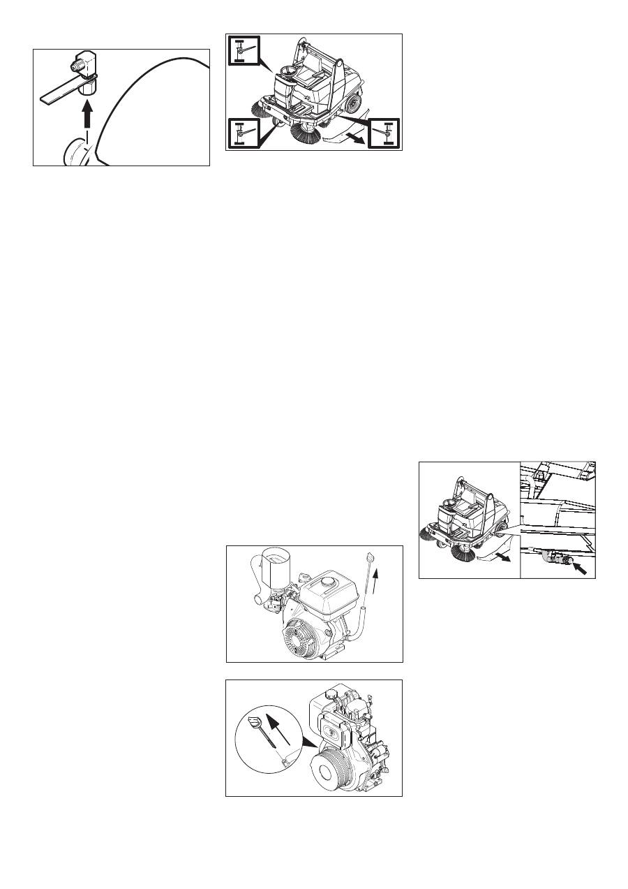
Loosen 3 retaining nuts on underside.
Clip side brush on to driver and screw
on.
Park the sweeper on an even surface.
Set programme switch to step 1 (driv-
ing). Roller brush is raised.
Turn ignition key to "0" and remove it.
Secure the machine with wheel
chock(s) to prevent it from rolling away.
Lock parking brake.
Remove belts or cords from roller
brush.
Replacement is due if a visible deteriora-
tion in sweeping performance caused by
bristle wear is evident.
Park the sweeper on an even surface.
Set programme switch to step 1 (driv-
ing). Roller brush is raised.
Turn ignition key to "0" and remove it.
Secure the machine with wheel
chock(s) to prevent it from rolling away.
Lock parking brake.
Open quick-release locks on the right-
hand side panel.
Check air filter and replace, if necessary
Clean and change spark plug (only KM
120/150 R G and R LPG)
Check and adjust fill level of hydraulic
fluid – sweeping hydraulics circuit
Check and adjust hydraulic fluid fill level
and change oil – axle drive circuit
Check oil filter/Check backflow pressure
Check side brush
Replacing side brush
Checking roller brush
Replacing roller brush
33 EN
-
14
Remove side panel.
Unscrew and withdraw bolt on the roller
brush swinging arm.
Pull out roller brush swinging arm.
Remove lifting rod assembly from pins.
Open quick-release locks and remove
cover.
Pull out roller brush.
Installation position of roller brush in direc-
tion of travel
Push new roller brush into the roller
brush housing and onto the drive pin.
Note
When installing the new roller brush, ensure
correct positioning of the bristle assembly.
Position roller brush cover.
Push lifting rod assembly on to pins.
Push roller brush mount on to the pins.
Tighten bolt on the roller brush mount.
Position retaining screws for the roller
brush cover and screw home.
Screw on side panel.
Note
Once the new roller brush has been in-
stalled, the sweeping track must be read-
justed.
Note
To do this, the machine must be in basic-
operating mode. The power button indica-
tor light should not light up.
Set programme switch to step 1 (driv-
ing). The side brush and roller brush are
raised.
Drive sweeper on to a smooth, even
surface covered with a visible layer of
dust or chalk.
Lower roller brush and allow it to briefly
rotate.
Raise roller brush.
Press pedal which raises bulk waste
flap and keep pressed.
Drive machine backwards.
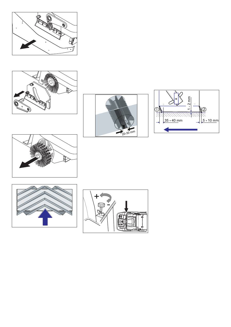
The sweeping track should have an even
rectangular shape which is between 20 and
30 mm wide.
Note
The shape of the sweeping track must not
be trapezoidal. If so, consult Customer Ser-
vice.
Note
The sweeping track can be adjusted using
a handwheel in basic-operating mode.
Open cover and secure it (Diag. 3).
Release the wing nut.
Enlarging sweeping track:
Turn the adjustment screw in an anti-
clockwise direction (+).
Reducing sweeping track:
Turn the adjustment screw in a clock-
wise direction (-).
Tighten the wing nut.
Note
In power-operating mode, the sweeping
track is automatically adjusted due to the
floating mounting for the side brush as the
bristles wear down. The roller brush must
be replaced if it becomes too worn.
Park the sweeper on an even surface.
Set programme switch to step 1 (driv-
ing). Roller brush is raised.
Turn ignition key to "0" and remove it.
Secure the machine with wheel
chock(s) to prevent it from rolling away.
Lock parking brake.
Open the side panel quick-release
locks on both sides.
Remove side panels.
Front sealing strip
Loosen retaining nuts for the front seal-
ing strip (1) slightly (to replace, un-
screw).
Screw on new sealing strip without fully
tightening the nuts.
Adjust sealing strip.
Set the distance of the sealing strip to
the floor so that the bottom edge trails
behind at a distance of between 35 and
40 mm.
Tighten nuts.
Rear sealing strip
Set the distance between the sealing
strip and the floor so that the bottom
edge trails behind at a distance of be-
tween 5 and 10 mm.
If worn, replace.
Remove roller brush.
Unscrew retaining nuts for rear sealing
strip (2).
Screw on new sealing strip.
Side sealing strips
Slightly loosen retaining nuts for the
side sealing strip (to replace, unscrew).
Screw on new sealing strip without fully
tightening the nuts.
To set the floor clearance, insert a
sheet with a thickness of between 1 and
2 mm under the sealing strip.
Adjust sealing strip.
Tighten nuts.
Screw on side panels.
Check and adjust roller brush sweeping
track
Adjusting and replacing sealing strips
34 EN
-
15
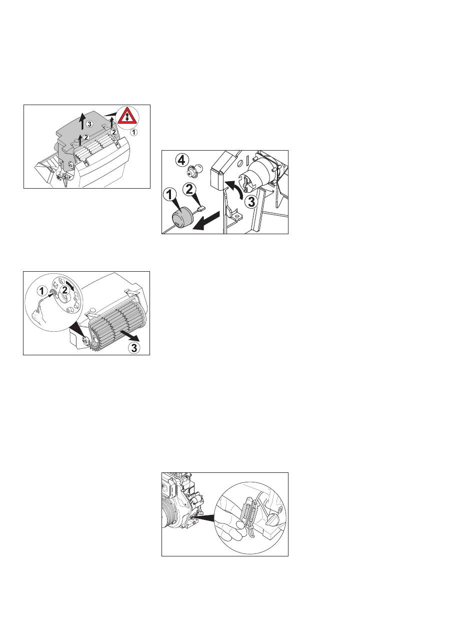
Danger
Empty waste container before replacing
dust filter. Wear a dust mask when working
around the dust filter. Observe safety regu-
lations on the handling of fine particulate
material.
Slightly raise the waste container and
tipp it a little.
Disconnect filter motor from power sup-
ply (1).
Disconnect the plug connection of the
limit switch.
Loosen the screw joint of the filter agita-
tor motor.
Open catches (2).
Slightly tip the filter box backwards and
take it out (3).
Loosen filter mount (1), turn (2) and pull
out.
Remove louver filter (3).
Insert new filter.
Make sure driver engages with grooves
on drive side.
Snap filter mount back on and tighten
screws.
Note
Make sure when installing the new filter
that the fins are not damaged and the filter
case seal does not get jammed.
Lift filter case seal out of groove in the
cover.
Insert new seal.
Danger
The engine requires approx. 3-4 seconds
to come to a standstill once it has been
switched off. During this time, stay well
clear of the working area.
Turn ignition key to "0" and remove it.
Open cover and secure it (Diag. 3).
Check tension of drive belt and V-belt of
the suction blower, also check for wear
or damage.
Check tension of drive belt and V-belt of
the roller brush also check for wear or
damage.
Only KM 120/150 R LPG and KM 120/
150 with driver cabin:
Check tension of drive belt and V-belt of
the light machine; also check for wear
or damage.
Chek the cup seal at the suction blower
regularly to see that it sits properly.
Turn ignition key to "0" and remove it.
Remove side brush.
Remove splash guard (1).
Disconnect plug (2).
Twist contact plate to one side (3).
Remove defective bulb (4).
Insert new bulb.
Twist contact plate back into original
position.
Connect plug.
Mount splash guard.
Screw on side brush.
The drive control/electronic system is in-
stalled behind the front panel. To replace a
fuse, the front panel must be removed.
Loosen screws on both sides of the
panel.
Note
The assignment of fuses is indicated on the
inside of the front panel. Only use fuses
with identical safety ratings.
Replace defective fuses.
Replace front panel.
Open cover and secure it (Diag. 3).
Replace defective fuse.
Replacing dust filter
Replacing filter case seal
Checking drive belt
Check cup seal
Replacing electric bulb
Replacing fuses of drive control/ elec-
tronic system
Replacing electrical starter in the engine
room (only KM 120/150 R D)
35 EN
Оглавление
- Inhaltsverzeichnis
- Funktion Bestimmungsgemäße Ver- wendung
- Bedien- und Funktionselemente
- Vor Inbetriebnahme
- Betrieb
- Stilllegung
- Transport Lagerung des Gerätes Pflege und Wartung
- Hilfe bei Störungen
- Technische Daten
- Zubehör
- Contents
- Function Proper use
- Operating and Functional Elements
- Before Startup
- Operation
- Shutdown
- Transport Storing the device Maintenance and care
- Troubleshooting
- Technical specifications
- Accessories
- Table des matières
- Fonction Utilisation conforme
- Eléments de commande et de fonction
- Avant la mise en service
- Fonctionnement
- Remisage
- Assistance en cas de panne
- Caractéristiques techniques
- Accessoires
- Indice
- Funzione Uso conforme a destinazione
- Elementi di comando e di funzione
- Prima della messa in funzione
- Funzionamento
- Fermo dell'impianto
- Guida alla risoluzione dei guasti
- Dati tecnici
- Accessori
- Inhoudsopgave
- Functie Reglementair gebruik
- Elementen voor de bediening en de functies
- Voor de inbedrijfstelling
- Werking
- Stillegging
- Hulp bij storingen
- Technische gegevens
- Toebehoren
- Índice de contenidos
- Función Uso previsto
- Elementos de operación y funcionamiento
- Antes de la puesta en marcha
- Funcionamiento
- Parada
- Ayuda en caso de avería
- Datos técnicos
- Accesorios
- Índice
- Funcionamento Utilização conforme o fim a que se destina a máquina
- Elementos de comando e de funcionamento
- Antes de colocar em funcio- namento
- Funcionamento
- Desactivação da máquina
- Ajuda em caso de avarias
- Dados técnicos
- Acessórios
- Indholdsfortegnelse
- Funktion Bestemmelsesmæssig an- vendelse
- Betjenings- og funktionselementer
- Inden ibrugtagning
- Drift
- Afbrydning/nedlæggelse
- Transport Opbevaring af maskinenPleje og vedligeholdelse
- Hjælp ved fejl
- Tekniske data
- Tilbehør
- Innholdsfortegnelse
- Funksjon Forskriftsmessig bruk
- Betjenings- og funksjonelementer
- Før den tas i bruk
- Drift
- Sette bort
- Transport Lagring av maskinen Pleie og vedlikehold
- Feilretting
- Tekniske data
- Tilbehør
- Innehållsförteckning
- Funktion Ändamålsenlig användning
- Manövrerings- och funktionselement
- Före ibruktagande
- Drift
- Nedstängning
- Transport Lagring av maskinen Skötsel och underhåll
- Åtgärder vid störningar
- Tekniska data
- Tillbehör
- Sisällysluettelo
- Toiminta Käyttötarkoitus
- Ohjaus- ja käyttölaitteet
- Ennen käyttöönottoa
- Käyttö
- Seisonta-aika
- Kuljetus Koneen säilytys Hoito ja huolto
- Häiriöapu
- Tekniset tiedot
- Tarvikkeet
- Πίνακας περιεχομένων
- Λειτουργία Χρήση σύμφωνα με τους κα - νονισμούς
- Προστασία περιβάλλοντος
- Στοιχεία χειρισμού και λειτουργίας
- Πριν τη θέση σε λειτουργία
- Λειτουργία
- Διακοπή της λειτουργίας
- Αποθήκευση της συσκευής Φροντίδα και συντήρηση
- Αντιμετώπιση βλαβών
- Τεχνικά χαρακτηριστικά
- Εξαρτήματα
- İ çindekiler
- Fonksiyon Kurallara uygun kullan ı m
- Kullan ı m ve çal ı ş ma elemanlar ı
- Cihaz ı çal ı ş t ı rmaya ba ş lama- dan önce
- Çal ı ş t ı rma
- Durdurma
- Ta ş ı ma Cihaz ı n depolanmas ı Koruma ve Bak ı m
- Ar ı zalarda yard ı m
- Teknik Bilgiler
- Aksesuar
- Оглавление
- Назначение Использование по назначе - нию
- Защита окружающей среды
- Описание элементов управления и рабочих узлов
- Перед началом работы
- Эксплуатация
- Вывод из эксплуатации
- Хранение прибора Уход и техническое обслу - живание
- Помощь в случае неполадок
- Технические данные
- Принадлежности
- Tartalomjegyzék
- Funkció Rendeltetésszer ű használat
- Kezelési- és funkciós elemek
- Üzembevétel el ő tt
- Üzem
- Leállítás
- Szállítás A készülék tárolása Ápolás és karbantartás
- Segítség üzemzavar esetén
- M ű szaki adatok
- Tartozékok
- Spis tre ś ci
- Funkcja U ż ytkowanie zgodne z prze- znaczeniem
- Elementy urz ą dzenia
- Przed pierwszym uruchomie- niem
- Dzia ł anie
- Wy łą czenie z eksploatacji
- Usuwanie usterek
- Dane techniczne
- Akcesoria


