Karcher Balayeuse KM 75-40 W G: 6 5 4 3 2 1
6 5 4 3 2 1: Karcher Balayeuse KM 75-40 W G
-
3
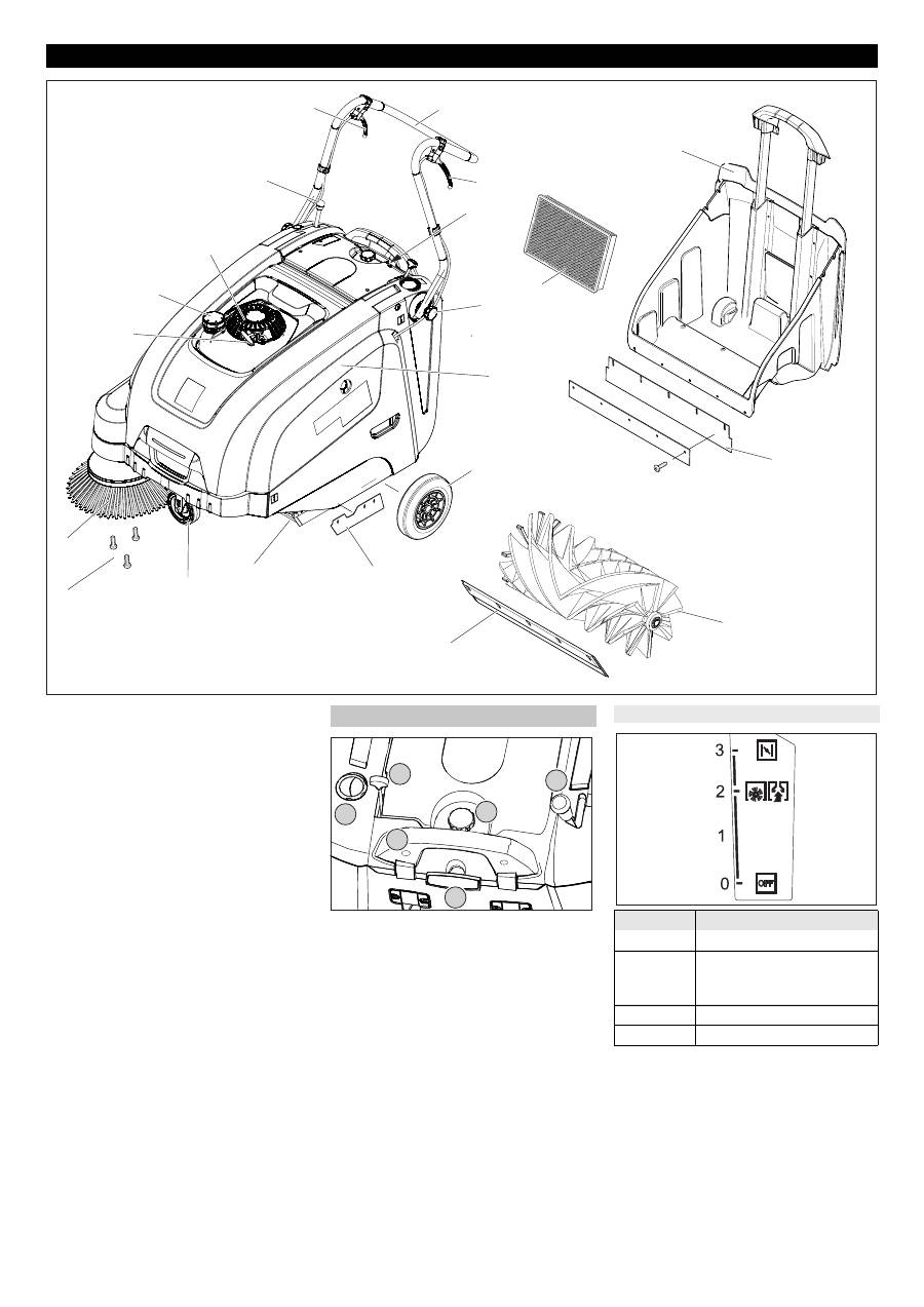
1 Starter rope
2 Tank lid
3 Petrol engine
4 Lever for lowering and raising the side-
brush
5 Lever to raise and lower the bulk waste
flap
6 Push handle
7 Lever for forward drive
8 Operating field
9 Fastening screw for slider
10 Dust filter
11 Waste container
12 Cover
13 Drive wheels
14 Rear sealing strip (at the waste contain-
er)
15 Roller brush
16 Front sealing strip
17 Side sealing strip
18 Bulk waste flap
19 Steering roller with fixed position brake
20 Fastener of the side brush
21 Side brushes
1 Multifunctional lever
2 Lever for lowering and raising the side-
brush
3 Locking screw of the dust filter cover
4 Locking bow of the waste container
5 Filter cleaning for dust filter
6 Wet/dry flap
Operating and Functional Elements
1
2
3
4
5
6
7
8
9
10
12
13
17
18
11
14
15
16
19
20
21
Operating field
6 5 4 3 2 1
Multifunctional lever
Position
Function
0/OFF
Motor off
1
Motor on/multifunctional le-
ver (speed steplessly adjust-
able)
2
Operating speed
3
Choke (cold start)
15
EN
-
4
Danger
Risk of injury, risk of damage!
Observe the weight of the appliance when
you load it!
Remove the cardboard.
Remove the wooden blocks that secure
the wheels and raise the device from
the pallette by hand.
Release parking brake.
Loosen the screws.
Align the pushing handle.
Tighten the screws.
Notice
–
The appliance may only be tilted back-
wards if the fuel tank is empty.
–
Close the fuel tap, remove the waste
container and move the pushing handle
to the front prior to tilting the appliance.
Do not rest the appliance on the push-
ing handle.
Clip side brush on to driver and screw
on.
Danger
Risk of injury! Switch off the appliance prior
to removing the waste container.
Notice
Only operate while the appliance hood is
closed. The appliance is equipped with a
hood contact switch to protect the operator.
The motor starts up only when the appli-
ance hood is closed.
Park the sweeper on an even surface.
Switch off engine.
Lock parking brake.
Danger
Risk of explosion!
–
Only use the fuels specified in the Op-
erations Manual.
–
Do not refuel the machine in enclosed
spaces.
–
Smoking and naked flames are strictly
prohibited.
–
Ensure that no fuel reaches the hot
open surfaces.
Switch off engine.
Open fuel filler cap.
Use "regular unleaded petrol".
Fill tank to max. 1 cm below the lower
edge of the filler nozzle.
Wipe off any spilt fuel and close fuel fill-
er cap.
Note
The machine can be operated for a maxi-
mum of 2.0 hours on a full tank.
Carry out the daily maintenance tasks (see
section "Maintenance and Care").
Check engine oil level.
Check and ensure proper fitting of the
spark plug.
Check side brush.
Check roller brush.
Shake off dust filter.
Empty waste container.
Danger
Ensure that there is adequate ventilation or
provision for diverting the exhaust gas
while operating the appliance in closed
rooms (risk of poisoning).
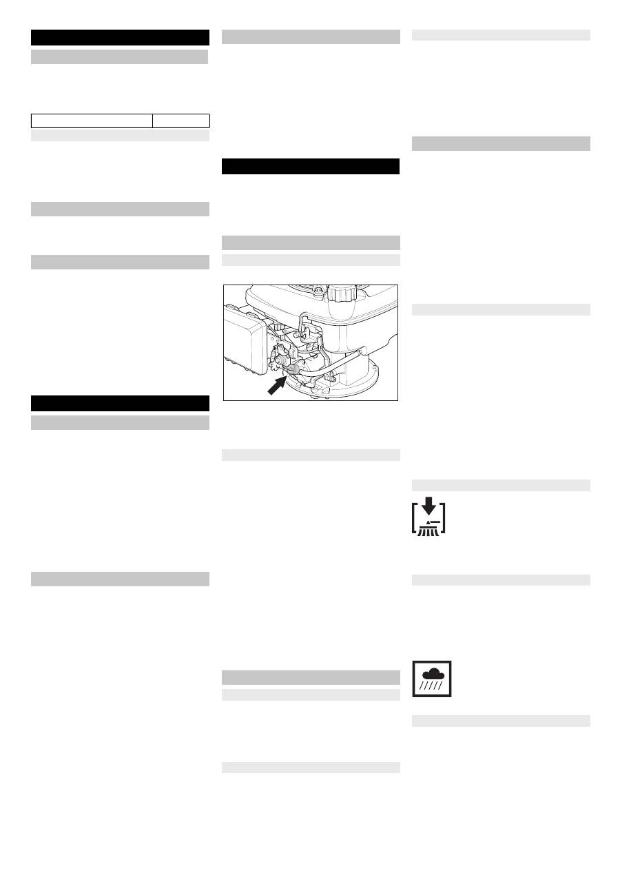
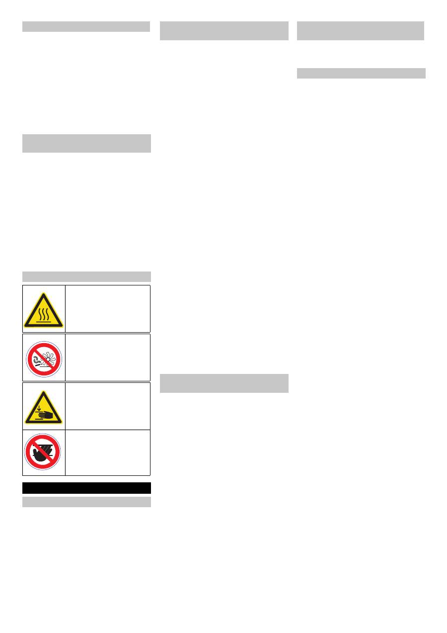
Open the device hood.
Open the fuel supply.
Turn the rotating knob parallel to the
hose of the fuel tap.
Close cover.
Release parking brake.
Slide the multifunctional lever into the
center position "Operation speed"; if the
weather is cold or wet, move it to the
"Choke“ position.
Pull the starter rope slowly until a resist-
ance can be felt.
Pull starter rope swiftly.
Once the motor runs, release the starter
rope. Move the multifunctional lever
from the "Choke" into the "Operating
speed" position.
Note
The appliance works best while in the
operating position.
Note
The sweep roller and the side-brushes start
rotating.
Pull the lever for forward drive.
Note
The drive speed for forward drive can be
adjusted steplessly depending on the posi-
tion of the lever.
Release the lever for forward drive. De-
vice comes to a halt.
Driving over fixed obstacles which are 30
mm high or less:
Raise bulk waste flap.
Drive forwards slowly and carefully.
Driving over fixed obstacles which are
more than 30 mm high:
Only drive over these obstacles using a
suitable ramp.
Danger
Risk of injury! If the bulk waste flap is open,
stones or gravel may be flung forwards by
the roller brush. Make sure that this does
not endanger persons, animals or objects.
몇
Warning
Do not sweep up packing strips, wire or
similar objects as this may damage the
sweeping mechanism.
Note
To achieve an optimum cleaning result, the
driving speed should be adjusted to take
specific situations into account.
Note
To sweep up larger items up to a height of
50 mm, e.g. cigarette packs, the bulk waste
flap must be raised briefly.
Raising bulk waste flap:
Pull the lever for raising the bulk waste
flap.
Lowering the bulk waste flap:
Release the lever for raising the bulk
waste flap.
Note
An optimum cleaning result can only be
achieved if the bulk waste flap has been
lowered completely.
Move the lever to lower the side brush
to the front. The side brush will be low-
ered.
Note
Empty the waste container at regular inter-
vals during the sweeping operation.
Note
During operation, the dust filter should be
shaken off and cleaned at regular intervals.
Close wet/dry flap
Open wet/dry flap.
Note
This protects the filter from moisture.
Before Startup
Unloading tips
Net weight (transport weight) 84 kg
Unloading
Installing the pushing handle
Install side brush
Start up
General notes
Refuelling
Inspection and maintenance work
Operation
Starting the machine
Open fuel cock
Start the engine
Drive the machine
Drive forward
Dry run
Driving over obstacles
Sweeping mode
Sweeping with bulk waste flap raised
Sweeping with side brushes
Sweeping dry floors
Sweeping damp or wet floors
16
EN
-
5
Pull the handle of the filter clean-off out
several times and reinsert it.
Danger
Risk of injury! Switch off the appliance prior
to removing the waste container.
Note
–
Make sure the seal strip is not damaged
while emptying the waste container.
–
The max. load of the waste container is
40 kg.
Shake off dust filter.
Pull lock bow of the waste container up-
ward.
Pull out the waste container.
Empty waste container.
Push in the waste container.
Push lock bow of the waste container
downward.
Switch off engine.
Push the multifunctional lever into
"OFF" position.
The side-brushes lift up.
Lock parking brake.
Open the device hood.
Close the fuel supply.
Turn the rotating knob perpendicular to
the fuel tap.
Close cover.
몇
Warning
The appliance must be secured against
slippage during transport.
Switch off engine.
Lock parking brake.
Empty fuel tank.
Secure the wheels of the machine with
wheel chocks.
Secure the machine with tensioning
straps or cables.
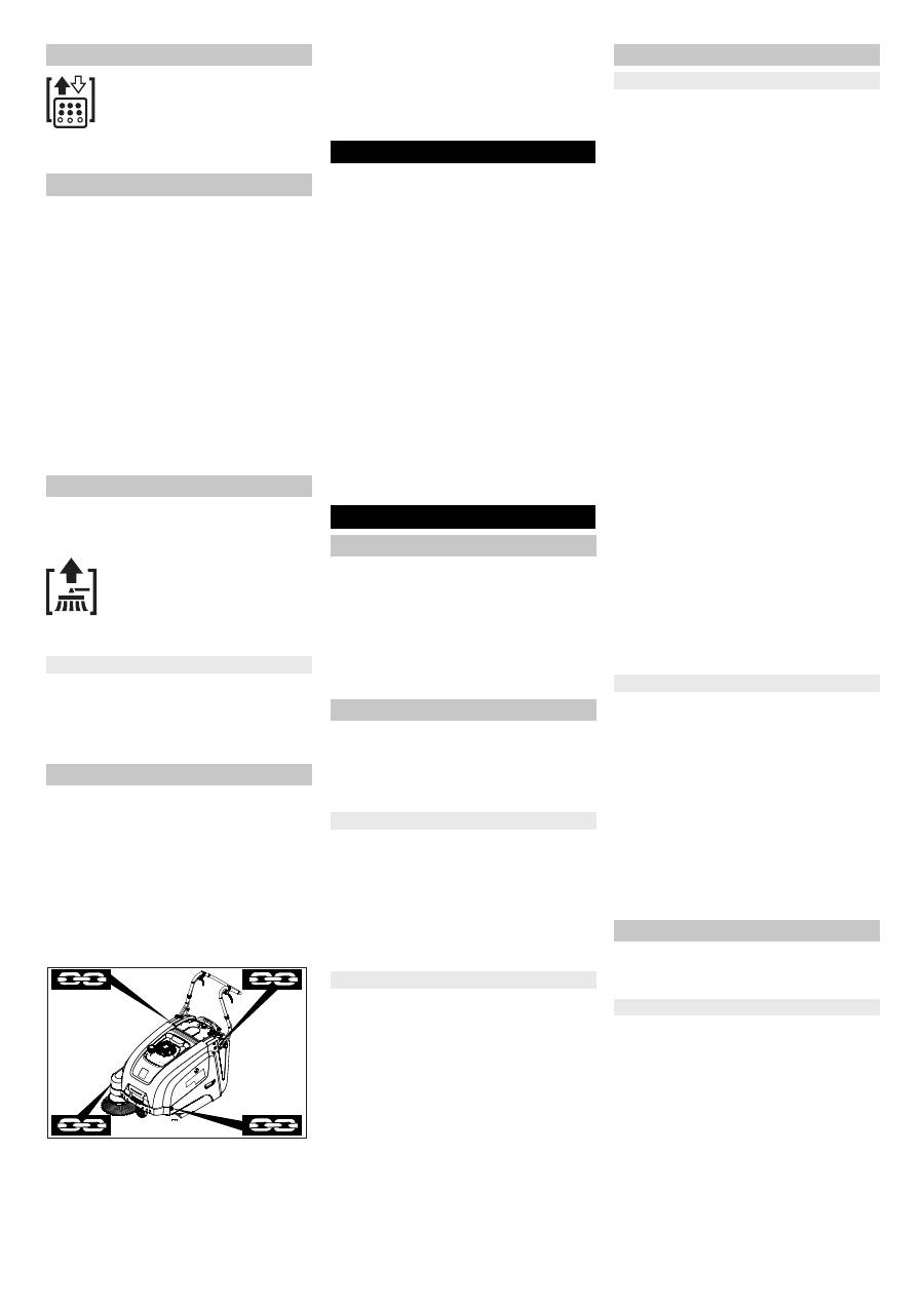
1 Fastening area above the pushing han-
dle
2 Fastening area under the device hood
Note
–
Observe markings for fixing points on
base frame (chain symbols).
–
Do not kink the bowden or sheathed ca-
bles.
Follow operating instructions of the en-
gine manufacturer!
If the sweeper is going to be out of service
for a longer time period, observe the follow-
ing points:
Park the sweeper on an even surface.
Switch off engine.
Lock parking brake.
Lock the sweeper to ensure that it does
not roll off.
Empty fuel tank.
Change engine oil.
Raise roller brush. Thus, engage both
adjustment levers in the top boring.
The side-brushes lift up.
Clean the inside and outside of the
sweeper.
Park the machine in a safe and dry
place.
– Maintenance work may only be carried
out by approved customer service out-
lets or experts in this field who are famil-
iar with the respective safety regula-
tions.
– Mobile appliances used for commercial
purposes are subject to safety inspec-
tions according to VDE 0701.
몇
Warning
Risk of damage! Do not clean the appliance
with a water hose or high-pressure water
jet (danger of short circuits or other dam-
age).
Danger
Risk of injury! Wear dust mask and protec-
tive goggles.
Open the device hood.
Clean machine with a cloth.
Blow through machine with com-
pressed air.
Close cover.
Clean the machine with a damp cloth
which has been soaked in mild deter-
gent.
Note
Do not use aggressive and abrasive clean-
ing agents.
Note
With a new motor, the oil must be changed
after the first 5 operating hours.
Daily maintenance:
Check engine oil level.
Check the sweeping roller and the side
brush for wear and wrapped belts.
Check function of all operator control el-
ements.
Weekly maintenance:
Check tension, wear and tear and func-
tioning of the drive belts.
Check for smooth running of the
Bowden cables and the moveable parts
Check the sealing strips in the sweep-
ing area for position and wear.
Check the sweeping track of the sweep-
ing roller.
Clean the dust filter.
Check air filter.
Maintenance to be carried out every 50
operating hours:
Perform a motor oil change.
Check spark plug.
Check function of hood contact switch.
Note
For description, see section on Care and
maintenance.
Note
Where maintenance is carried out by the
customer, all service and maintenance
work must be undertaken by a qualified
specialist. If required, a specialised Archer
dealer may be contacted at any time.
Maintenance to be carried out after 5 op-
erating hours:
Carry out initial inspection.
Maintenance to be carried out every 100
operating hours
Maintenance to be carried out every 300
operating hours
Note
In order to safeguard warranty claims, all
service and maintenance work during the
warranty period must be carried out by the
authorised KÄRCHER specialist in accord-
ance with the maintenance booklet.
Preparation:
Park the sweeper on an even surface.
Lock parking brake.
Danger
Risk of injury!
The engine requires approx. 3-4 seconds
to come to a standstill once it has been
switched off. During this time, stay well
clear of the working area.
– Allow the machine sufficient time to cool
down before carrying out any mainte-
nance and repair work.
– Do not touch any hot parts, such as the
drive motor and exhaust system.
Cleaning the dust filter
Emptying waste container
Turn off the appliance
Close fuel cock
Transport
Shutdown Maintenance and care
General notes
Cleaning
Cleaning the inside of the machine
External cleaning of the appliance
Maintenance intervals
Maintenance by the customer
Maintenance by Customer Service
Maintenance Works
General notes on safety
17
EN
-
6
Note
–
The appliance may only be tilted back-
wards if the fuel tank is empty.
–
Close the fuel tap, remove the waste
container and move the pushing handle
to the front prior to tilting the appliance.
Do not rest the appliance on the push-
ing handle.
Switch off the appliance prior to clean-
ing and performing any maintenance
tasks or replacing parts.
Danger
Risk of burns!
Allow engine to cool down.
Wait for at least 5 minutes after switch-
ing off the engine before checking the
engine oil fill level.
Open the device hood.
Unscrew and withdraw oil dipstick.
Wipe off oil dipstick and screw it in.
Unscrew and withdraw oil dipstick.
Read the value of the oil level.
– The oil level must lie between “MIN“
and “MAX“ marking.
– Add motor oil if the oil level is below the
"MIN" marking.
– Do not fill oil above the "MAX" marking.
Fill motor oil into the oil fill neck.
Oil grade: see Technical Data
Reinsert the oil dipstick.
Wait at least 5 minutes.
Check engine oil level.
Danger
Risk of burns due to hot oil!
Allow engine to cool down.
Open the device hood.
Unscrew and withdraw oil dipstick.
Draw off engine oil via the oil filler neck
using 6.491-538 oil-change pump.
Fill motor oil into the oil fill neck.
Oil grade: see Technical Data
Reinsert the oil dipstick.
Wait at least 5 minutes.
Check engine oil level.
Remove covering lid.
Take out the filter inlay.
Insert a new filter insert.
The filter lamella must point into the di-
rection of the locking cap.
Attach the locking cap.
Remove spark-plug connector.
Unscrew and clean spark plug.
Screw in cleaned or new spark plug.
Push on spark-plug connector.
Open the device hood.
Close the fuel supply.
Turn the rotating knob perpendicular to
the fuel tap.
Press together the fuel hose from the
tank to the fuel tap.
Loosen the hose clamp on the fuel tap.
Remove the fuel hose.
Open fuel filler cap.
Hold the fuel hose over a suitable catch
bin and drain the fuel.
If the tank is empty, reattach the fuel
hose to the stub of the fuel tap and in-
stall the hose clamp.
This must be adjusted if the drive perfor-
mance of the appliance becomes insuffi-
cient when driving uphill.
Loosen counter-nut.
Adjust the adjustment screw.
Tighten the counter-nut.
Lock parking brake.
Remove the waste container.
Remove belts or cords from roller
brush.
Replacement is due if a visible deteriora-
tion in sweeping performance caused by
bristle wear is evident.
Note
–
The appliance may only be tilted back-
wards if the fuel tank is empty.
–
Close the fuel tap, remove the waste
container and move the pushing handle
to the front prior to tilting the appliance.
Do not rest the appliance on the push-
ing handle.
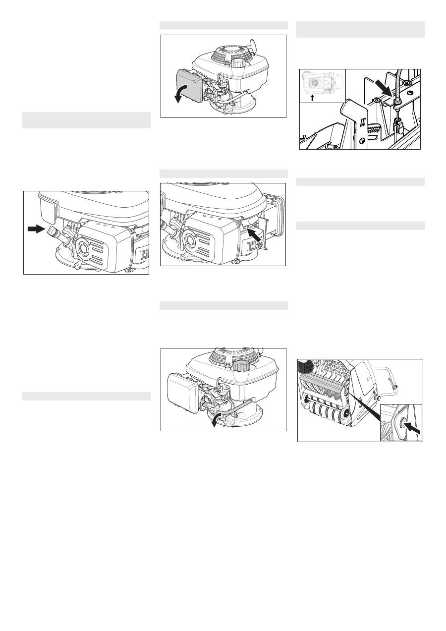
Lock parking brake.
Close fuel cock.
Remove the waste container.
Tilt the appliance rearward.
Lift the waste flap, press in the bearing
cap and swivel the roller brush toward
the front.
Pull out roller brush.
Attach the new roller brush to the drive
pin (left).
Engage the bearing cup into the boring
of the roller brush swinging arm on the
opposite side.
몇
Warning
Risk of damage! Make sure that no bristles
are jammed into the boring of the roller
brush swinging arm.
Note
Once the new roller brush has been in-
stalled, the sweeping track must readjust-
ed.
Check engine oil level and top up, if
required
Change the engine oil
Change the air filter
Clean or replace the spark plug
Empty fuel tank
Adjust the Bowden cable of the
acceleration drive
Checking roller brush
Replacing roller brush
18
EN
-
7
Raise the sweeper from the front and
drive it on to a smooth, even surface
covered with a visible layer of dust or
chalk.
Lock parking brake.
Let the sweeping roller rotate for ap-
prox. 15-30 seconds.
Raise the sweeper at the front and drive
it towards the side.
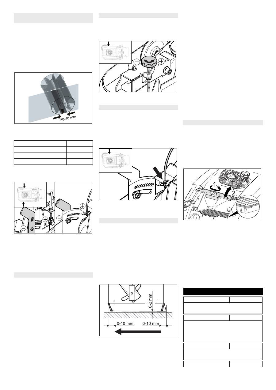
The sweeping track should have an even
rectangular shape which is between 30 and
40 mm wide.
Adjust sweeping track:
Adjust the left and right adjustment le-
vers and engage into the same boring.
– Engage adjustment lever into the lower
boring (+): Sweeping track becomes
bigger
– Engage the adjustment lever into the
upper boring (-): Sweeping track be-
comes smaller
Check sweeping mirror.
Replacement is due if a visible deteriora-
tion in sweeping performance caused by
bristle wear is evident.
Note
–
The appliance may only be tilted back-
wards if the fuel tank is empty.
–
Close the fuel tap, remove the waste
container and move the pushing handle
to the front prior to tilting the appliance.
Do not rest the appliance on the push-
ing handle.
Unscrew 3 screws from the underside
of the side brush.
Remove the wiper blade.
Clip new side brushes on to driver and
screw on.
Adjustment is necessary if a visible deterio-
ration in sweeping performance caused by
side-brush is evident.
Release the wing nut.
Adjust the adjustment screw.
Tighten the wing nut.
– Adjustment is necessary if the bulk
waste flap cannot be raised wide
enough.
– The Bowden cable needs to be re-
leased a little if the sweeper results be-
come poorer, for e.g. due to the wearing
of the front lip.
Loosen counter-nut.
Adjust the adjustment screw.
Tighten the counter-nut.
Note
–
The appliance may only be tilted back-
wards if the fuel tank is empty.
–
Close the fuel tap, remove the waste
container and move the pushing handle
to the front prior to tilting the appliance.
Do not rest the appliance on the push-
ing handle.
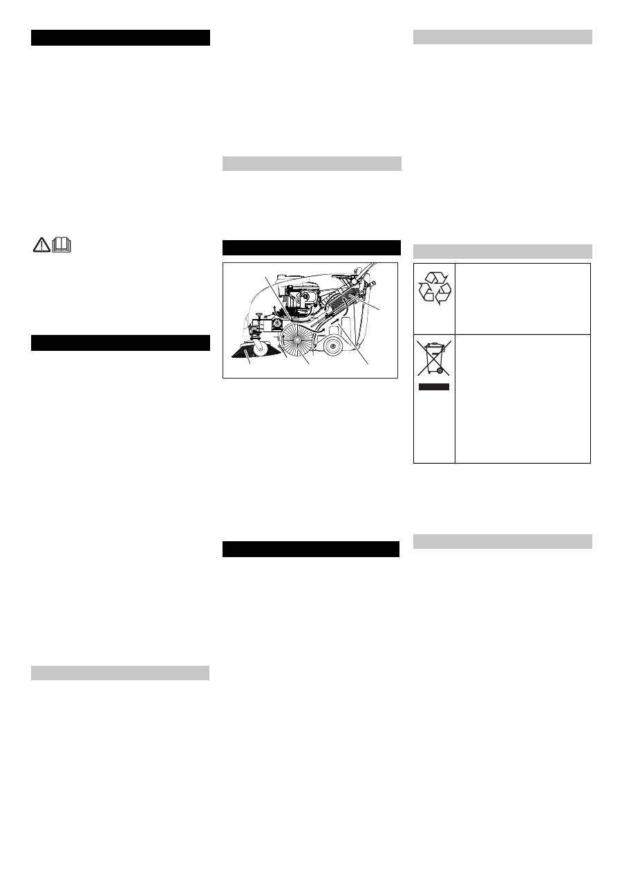
Front sealing strip
Loosen the fastening screws of the
sealing strip.
Adjust or replace sealing strip.
Set the distance between the sealing
strip and the floor so that the bottom
edge trails behind at a distance of be-
tween 0-10 mm.
Adjust sealing strip.
Tighten the fastening of the sealing
strip.
Rear sealing strip
Remove the waste container.
Loosen the fastening screws of the
sealing strip.
Adjust or replace sealing strip.
Set the distance between the sealing
strip and the floor so that the bottom
edge trails behind at a distance of be-
tween 0-10 mm.
Tighten the fastening of the sealing
strip.
Side sealing strips
Loosen the fastening screws of the
sealing strip.
Adjust or replace sealing strip.
To set the floor clearance, insert a
sheet with a thickness of max. 2 mm un-
der the sealing strip.
Adjust sealing strip.
Tighten the fastening of the sealing
strip.
Danger
Empty waste container before replacing
dust filter. Wear a dust mask when working
around the dust filter. Observe safety regu-
lations on the handling of fine particulate
material.
Lock parking brake.
Shake off dust filter.
Open the locking screw of the dust filter
cover in an anticlockwise direction.
Lift the dust filter cover.
Replace dust filter Make sure the dust
filter is inserted correctly (see figure).
Screw in the locking screw all the way.
몇
Warning
If the locking screw is not tightened all the
way, there may be damages.
Note
Make sure when installing the new filter
that the fins are not damaged.
Check and adjust roller brush sweeping
track
Setting range
(-) 1...10 (+)
Minimum sweeping track
1
Maximum sweeping track
10
New roller brush
1...3
Replacing side brush
R
L
R L
Adjust side-brush lowering
Adjust the raising of the bulk waste flap
Adjusting and replacing sealing strips
Replacing dust filter
Accessories
Hard side-brushes
6.905-625.0
For removing stubborn dirt in the external
area; resistant to moisture.
Roller-brush, soft
6.906-886.0
With natural bristles especially for fine dust
sweeping on smooth indoor floors. Not re-
sistant to wetness; not for abrasive surfac-
es.
Roller-brush, hard
6.906-885.0
For removing stubborn dirt in the external
area; resistant to moisture.
Roller brush, antistatic 6.906-950.0
19
EN

-
8
Troubleshooting
Fault
Remedy
Appliance cannot be started
Close appliance hood
Check the hood contact switches
Refuel
Open fuel cock
Check and clean spark plug, replace if necessary.
Check setting of multifunctional lever
Check bowden cable to the motor
Inform Kärcher Customer Service.
Engine is running but machine is
not moving
Adjust the Bowden cable of the acceleration drive
Checking the V-Belt
Inform Kärcher Customer Service.
Device comes to halt while climbing
a slope
Drive over a path with lesser slope
Adjust the Bowden cable of the acceleration drive
Checking the V-Belt
Inform Kärcher Customer Service.
Machine is not sweeping properly Check roller brush and side brushes for wear, replace if necessary.
Check function of bulk waste flap
Release the Bowden cable of the bulk waste flap (adjustment screw)
Check belts for tension and functioning; replace, if required
Adjust roller mirror
Replacing roller brush
Inform Kärcher Customer Service.
Dust gathers in the machine
Check function of bulk waste flap
Release the Bowden cable of the bulk waste flap (adjustment screw)
Check dust filter, clean or replace
Empty waste container
Replace sealing profile at the waste container
Check the seal on the dust filter
Check sealing strips for wear, adjust or replace as required
Poor cleaning performance at edges Adjust side-brush lowering
Replace side brush
Lower the side brushes
Check the drive belt of the side brush
Inform Kärcher Customer Service.
Side-brush raising does not func-
tion
Check Bowden cable of the side-brush raising
Inform Kärcher Customer Service.
The new roller brush brushes
against the waste container
Correct the setting of the sweep track; for this, engage both adjustment levers into the upper boring
(1...3)
20
EN

-
9
Technical specifications
KM 75/40 W G
Machine data
Length x width x height (pushing handle unfolded)
mm
1430 x 750 x 1190
Length x width x height (pushing handle folded in)
mm
1160 x 750 x 930
Unladen weight
kg
84
Driving and sweeping speed
km/h
4,5
Climbing capability (max.)
%
15
Roller brush diameter
mm
265
Side brush diameter
mm
410
Surface area, max.
m
2
/h
3400
Working width without side brushes
mm
550
Working width with side-brush
mm
750
Volume of waste container
l
40
Protection type, drip-proof
--
IPX 3
Engine
Type
--
Honda, 1 cyl., four-stroke
GCV 160
Cylinder capacity
cm
3
160
Operating speed
1/min
2600 ±50
Max. power
kW/PS
3,3/4,5
Capacity of fuel tank, normal petrol (unleaded)
l
0,9
Motor oil (SF, SG)
l
0,50 (SAE 10W30)
Spark plug, NGK
--
BPR 6 ES
Filter and vacuum system
Filter surface area, fine dust filter
m
2
1,8
Category of use – filter for non-hazardous dust
--
L
Nominal vacuum, suction system
mbar
5
Nominal volume flow, suction system
l/s
45
Working conditions
Temperature
°C
-5 and +40
Air humidity, non-condensing
%
0 - 90
Noise emission
Sound pressure level (EN 60704-1)
dB(A)
75
Guaranteed sound power level (2000/14/EC)
dB(A)
92
Machine vibrations
Vibration total value (ISO 5349)
Upper limbs
m/s
2
1,21
21
EN

-
10
We hereby declare that the machine de-
scribed below complies with the relevant
basic safety and health requirements of the
EU Directives, both in its basic design and
construction as well as in the version put
into circulation by us. This declaration shall
cease to be valid if the machine is modified
without our prior approval.
The undersigned act on behalf and under
the power of attorney of the company man-
agement.
Authorised Documentation Representative
S. Reiser
Alfred Kärcher GmbH Co. KG
Alfred-Kärcher-Str. 28 - 40
71364 Winnenden (Germany)
Phone: +49 7195 14-0
Fax: +49 7195 14-2212
Winnenden, 2011/08/01
EC Declaration of Conformity
Product:
Vacuum sweeper
Type:
1.049-xxx
Relevant EU Directives
2006/42/EC (+2009/127/EC)
2004/108/EC
2000/14/EC
Applied harmonized standards
EN 55012: 2007 + A1: 2009
EN 55014–2: 1997+A1: 2001+A2: 2008
EN 60335–1
EN 60335–2–72
Applied national standards
--
Applied conformity evaluation method
2000/14/EC: Appendix V
Sound power level dB(A)
KM 75/40 W G
Measured:
89
Guaranteed: 92
CEO
Head of Approbation
22
EN
-
1
Lire ce manuel d'utilisation origi-
nal avant la première utilisation
de votre appareil, le respecter et le conser-
ver pour une utilisation ultérieure ou pour le
futur propriétaire.
Avant la première mise en service, vous
devez impérativement avoir lu les
consignes de sécurité N° 5.956-250 !
L'utilisation de l'appareil doit être faite en
conformité avec les consignes figurant
dans les instructions de service.
Il est nécessaire de contrôler l'état et la
sécurité du fonctionnement de l'appa-
reil et de ses équipements avant toute
utilisation. Ne pas utiliser l'appareil si
son état n'est pas irréprochable.
– Cette balayeuse est conçue pour le ba-
layage de surfaces encrassées en inté-
rieur et en extérieur.
– L'appareil n'est pas destiné au net-
toyage de voies publiques.
– Cet appareil n'est pas conçu pour aspi-
rer des poussières nocives.
– Aucune transformation ne doit être ef-
fectuée sur la machine.
– Cet appareil convient uniquement pour
les revêtements de sol mentionnés
dans le mode d'emploi.
– Il doit exclusivement être utilisé sur des
surfaces autorisées par l'entrepreneur
ou son représentant.
– En règle générale, il convient : d'éloi-
gner les matériaux facilement inflam-
mables de la machine (risque d'explo-
sion ou d'incendie).
– Ne jamais aspirer ni balayer de liquides
explosifs, de gaz inflammables, ni
d'acides ou de solvants non dilués ! Il
s'agit notamment de substances telles
que l'essence, les diluants pour pein-
tures, ou le fuel, qui, en tourbillonnant
avec l'air aspiré, risqueraient de pro-
duire des vapeurs ou des mélanges, ou
de substances telles que l'acétone, les
acides ou les solvants non dilués, qui
pourraient altérer les matériaux consti-
tutifs de l'appareil.
– Ne jamais balayer/aspirer de pous-
sières réactives de métal (par ex. alumi-
nium, magnésium, zinc) ; elles forment
des gaz explosifs en combinaison avec
des détergents alcalins et acides.
– N’aspirer ou ne balayer aucun objet en
flamme ou incandescent.
– Il est interdit de séjourner dans la zone
à risque. Il est interdit d’exploiter l’appa-
reil dans des pièces présentant des
risques d’explosion.
– Asphalte
– Sol industriel
– Chape coulée
– Béton
– Pavé
La balayeuse fonctionne selon le principe
du balayage par soulèvement et projection.
– Le balai latéral (1) nettoie les angles et
les bordures de la surface à balayer et
achemine les déchets dans la zone
d'action de la brosse rotative.
– La brosse rotative (2) rejette directe-
ment les déchets dans le bac à pous-
sières (3).
– La poussière qui se soulève dans le ré-
servoir est recueillie par le filtre à pous-
sières (4) et l'air filtré est aspiré par l'as-
pirateur (5).
Contacter le revendeur en cas de constata-
tion d'une avarie de transport lors du débal-
lage de l'appareil.
– Lire et respecter les instructions de ser-
vice et les consignes de sécurité des
dispositifs de travail placés sur l'appa-
reil.
– Afin d'assurer un fonctionnement sans
danger, observez les avertissements et
consignes placés sur l'appareil.
– Outre les instructions figurant dans le
mode d'emploi, il est important de
prendre en considération les consignes
générales de sécurité et de prévention
contre les accidents imposées par la loi.
Danger
Afin d'éviter tout danger, seul le service
après-vente agréé est habilité à effectuer
des réparations ou à monter des pièces de
rechanger sur l'appareil.
– Utiliser uniquement des accessoires et
des pièces de rechange autorisés par le
fabricant. Des accessoires et des
pièces de rechange d’origine garan-
tissent un fonctionnement sûr et parfait
de l’appareil.
– Une sélection des pièces de rechange
utilisées le plus se trouve à la fin du
mode d'emploi.
– Vous trouverez plus d'informations sur
les pièces de rechange dans le menu
Service du site www.kaercher.com.
Instructions relatives aux ingrédients
(REACH)
Les informations actuelles relatives aux in-
grédients se trouvent sous :
www.kaercher.com/REACH
Dans chaque pays, les conditions de ga-
rantie en vigueur sont celles publiées par
notre société de distribution responsable.
Les éventuelles pannes sur les acces-
soires sont réparées gratuitement dans le
délai de validité de la garantie, dans la me-
sure où celles-ci relèvent d'un défaut maté-
riel ou d'un vice de fabrication. En cas de
recours en garantie, adressez-vous à votre
revendeur ou au service après-vente agréé
le plus proche munis de votre preuve
d'achat.
Contenu
Utilisation conforme . . . . . . . . . FR
1
Fonction. . . . . . . . . . . . . . . . . . FR
1
Consignes générales. . . . . . . . FR
1
Consignes de sécurité . . . . . . . FR
2
Eléments de commande et de
fonction . . . . . . . . . . . . . . . . . . FR
3
Avant la mise en service . . . . . FR
4
Mise en service . . . . . . . . . . . . FR
4
Fonctionnement. . . . . . . . . . . . FR
4
Remisage . . . . . . . . . . . . . . . . FR
5
Entretien et maintenance. . . . . FR
5
Accessoires . . . . . . . . . . . . . . . FR
8
Assistance en cas de panne . . FR
9
Caractéristiques techniques . . FR
10
Déclaration de conformité CE . FR
11
Utilisation conforme
Mauvaise utilisation prévisible
Revêtements appropriés
Fonction Consignes générales 5 4 1 2 3
Accessoires et pièces de rechange
Protection de l’environnement
Les matériaux constitutifs de
l’emballage sont recyclables. Ne
pas jeter les emballages dans
les ordures ménagères, mais les
remettre à un système de recy-
clage.
Les appareils usés contiennent
des matériaux précieux recy-
clables lesquels doivent être ap-
portés à un système de recy-
clage. Il est interdit de jeter les
batteries, l'huile et les subs-
tances similaires dans l'environ-
nement. Pour cette raison, utili-
ser des systèmes de collecte
adéquats afin d'éliminer les ap-
pareils hors d'usage.
Garantie
23
FR
-
2
– Utiliser uniquement des accessoires et
des pièces de rechange autorisés par le
fabricant. Des accessoires et des
pièces de rechange d’origine garan-
tissent un fonctionnement sûr et parfait
de l’appareil.
– Une sélection des pièces de rechange
utilisées le plus se trouve à la fin du
mode d'emploi.
– Vous trouverez plus d'informations sur
les pièces de rechange dans le menu
Service du site www.kaercher.com.
Danger
Signale la présence d'un danger imminent
entraînant de graves blessures corporelles
et pouvant avoir une issue mortelle.
몇
Avertissement
Signale la présence d'une situation éven-
tuellement dangereuse pouvant entraîner
de graves blessures corporelles et même
avoir une issue mortelle.
Attention
Remarque relative à une situation éven-
tuellement dangereuse pouvant entraîner
des blessures légères ou des dommages
matériels.
Contacter le revendeur en cas de constata-
tion d'une avarie de transport lors du débal-
lage de l'appareil.
– Afin d'assurer un fonctionnement sans
danger, observez les avertissements et
consignes placés sur l'appareil.
– Outre les instructions figurant dans le
mode d'emploi, il est important de
prendre en considération les consignes
générales de sécurité et de prévention
contre les accidents imposées par la loi.
Danger
Risque de blessure !
Risque de basculement en cas de pente
trop forte.
–
Dans le sens de la marche, ne pas
monter des pentes supérieures à 15%.
Risque de basculement en cas de sol ins-
table.
–
N'utilisez la machine que sur des sols
stabilisés.
Risque de basculement en cas de pente la-
térale trop importante.
–
N'empruntez aucune pente supérieure
à 15% dans le sens perpendiculaire au
sens de la marche.
– Doivent être respectées les mesures de
règlement, les règles et les décrets qui
sont valables pour les automobiles.
– L’utilisateur doit utiliser l’appareil de fa-
çon conforme. Dans la circulation, il doit
prendre en considération les données
locales et lors du maniement de l’appa-
reil, il doit prendre garde aux tierces
personnes, et en particulier aux en-
fants.
– L'appareil doit uniquement être utilisée
par des spécialistes qui sont instruits
dans la manoeuvre ou par des per-
sonnes qui peuvent justifiée leur apti-
tude d'utilisation et qui sont explicite-
ment mandatées pour l'utilisation.
– Ne jamais laisser des enfants ou des
adolescents utiliser l'appareil.
L'appareil ne doit pas rester sans sur-
veillance pendant tout le temps où le
moteur fonctionne. L'opérateur ne peut
quitter l'appareil que lorsque le moteur
est arrêté, l'appareil assuré contre des
mouvements involontaires et le frein de
stationnement actionné.
Danger
Risque de blessure !
–
Le quatrième trou ne peut être fermé.
–
Ne pas se pencher au-dessus ou tou-
cher le quatrième trou (danger de brû-
lure).
–
Ne pas toucher le moteur de traction
(danger de brûlure).
–
Pour une utilisation de l'appareil dans
des locaux fermés, il doit être garanti
une ventilation suffisante et une éva-
cuation des gazes résiduels (danger
d'intoxication).
–
Les gaz résiduels sont toxiques et no-
cifs, ils ne peuvent être respirés.
–
Le moteur continue à tourner 3 ou 4 se-
condes après l'arrêt. Ne pas s'appro-
cher de la zone de travail pendant ce
laps de temps.
–
La machine ne doit être basculée en ar-
rière qu'avec un réservoir à carburant
vide.
Au transport, le moteur de l'appareil doit
être arrêté et l'appareil doit être bien fixé.
Cf. chapitre « Transport ».
Danger
Si le capot de la machine est ouvert alors
que le moteur tourne, le moteur doit être
coupé. Si le moteur ne s'éteint pas, le
contacteur capot est défectueux. Informer
le service après-vente.
Pièces de rechange
Symboles utilisés dans le mode
d'emploi
Symboles sur l'appareil
Risque de brûlure provoqué
par les pièces chaudes de
l'installation!
Ne pas balayer d'objets en
feu ou brûlants, comme
par.ex. des cigarettes, des
allumettes ou autre.
Risque d'écrasement et de
coupure à la courroie, au
balai latéral, au réservoir, à
l'étrier de poussée.
Risque de blessure par les
pièces en rotation. Ouvrir le
capot seulement lorsque le
moteur est à l'arrêt.
Consignes de sécurité
Consignes générales
Consignes de sécurité relatives au
mode de déplacement
Consignes de sécurité relatives au
moteur à combustion
Consignes de sécurité relatives au
transport de l'appareil
Ouvrir/fermer le capot de l'appareil
24
FR
