LG PQNFB17B0: инструкция
Раздел: Аксессуары для аудио
Тип:
Инструкция к LG PQNFB17B0

ENGLISH ITALIANO
ESPAÑOL
FRANÇAIS
DEUTSCH CHINESE
РУССКИЙ ЯЗЫК
INSTALLATION/OWNER MANUAL
AIR CONDITIONER
Please read this manual carefully before operating
your set and retain it for future reference.
TYPE : BNU-BAC(BACnet Gateway)
P/NO : MFL37115823
www.lg.com

BNU-BAC(BACnet Gateway)
TABLE OF CONTENTS
Safety Precautions .....................................................................................................3-6
Main Features & Specification ................................................................................7-10
Denomination for each component............................................................................11
How to install
- System Diagram ...............................................................................................12-13
- Installation Order....................................................................................................14
- Hardware Installation ........................................................................................15-21
- Software Installation .........................................................................................22-27
LG's BACnet Gateway Agreement .............................................................................28
Test Operation Procedure......................................................................................29-48
Function Specifications BACnet Gateway
- Summary................................................................................................................49
- Configuration of Connection ..................................................................................49
- Monitoring and Controlling Items of A/C ................................................................50
- Monitoring and Controlling point of indoor and ventilator.......................................51
BACnet Protocol Implementation Conformance Statement(PICS)
- BACnet Protocol Implementation Conformance Statement..............................52-53
Objects (BACnet/IP)
- Supported Object Type ..........................................................................................54
- BACnet Point List : Indoor Unit ........................................................................55~56
- BACnet Point List : Ventilation .........................................................................57~58
- BACnet Point List : AHU ..................................................................................59~62
- Example of Point Table ..........................................................................................63
Objects (Modbus-TCP)
- Supported Function Code ......................................................................................64
- Modbus Point List : Indoor Unit........................................................................65~66
- Modbus Point List : Vent ..................................................................................67~68
- Modbus Point List : AHU..................................................................................69~72
- Example of Point Table ....................................................................................73~74
Detailed Explanation of Object.............................................................................75~83
Initialization at the Start Up ........................................................................................84
Report Function
- Event Notification ...................................................................................................84
- COV(Change Of Value) Notification.......................................................................85
Trouble Shooting ...................................................................................................86~90
How to differentiate between Direct Cable & Cross Cable ......................................91
Guide for the open source software ..........................................................................92
Appendix1. BACnet Interoperability Building Blocks Supported(BIBBs)........93~97
Appendix2. Object Property table......................................................................98~106
Appendix3. BACnet Gateway Error Response table ..............................................107
Note : After the LC BACnet Gateway agreement part, please scrutinize with Companies specialized in BMS.
2 BACnet Gateway
Safety Precautions
■ Operation
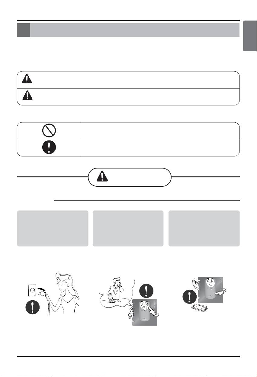
Do not operate or stop
Ask for Product
Use standard parts.
the unit by inserting or
equipment at the service
pulling out the power
center or establishment
plug.
certainly at the specialty
store.
• Use of non standard parts
• It will cause electric shock
• It can cause an accident,
can cause electric shock,
or fire due to heat
electric shock, explosion
explosion, injury,
generation.
or injury.
breakdown.
Installation/Owner Manual 3
LG-NET 1
TX
RX
1
2
DI
LG-NET 2
TX
RX
3
LG-NET 3
TX
4
5
LG-NET 4
RX
TX
6
RX
7
8
9
10
Ext 1
TX
RX
11
Ext 2
TX
12
RX
13
14
15
16
Ethernet 1
ACT
17
18
MENU/
LNK
19
SELECT
Ethernet 2
ACT
20
LNK
Console
TX
RX
1
2
3
DO
Run
4
Power
LG-NET 1
TX
RX
1
2
DI
LG-NET 2
TX
3
LG-NET 3
RX
TX
4
RX
5
TX
6
LG-NET 4
RX
7
8
9
Ext 1
TX
10
11
Ext 2
RX
TX
12
RX
13
14
15
16
Ethernet 1
ACT
17
18
MENU/
LNK
19
SELECT
Ethernet 2
ACT
20
LNK
Console
TX
RX
1
2
3
DO
Run
4
Power
Safety Precautions
To prevent injury to the user or other people and property damage, the following instructions
must be followed.
■ Incorrect operation due to ignoring instruction will cause harm or damage. The seriousness is
classified by the following indications.
■ Meanings of symbols used in this manual are as shown below.
WARNING
CAUTION
This symbol indicates the possibility of death or serious injury.
This symbol indicates the possibility of injury or damage.
Be sure not to do.
Be sure to follow the instruction.
WARNING
ENGLISH
Standard Parts
If water enters the product, turn the power
Keep the product away from the places
switch of the main body of appliance off.
which can have moisture.
• After taking the power-plug out from the
• Water may enter the unit and degrade the
socket, contact the service center.
insulation. It may cause an electric shock.
LG-NET 1
TX
RX
1
2
DI
LG-NET 2
TX
LG-NET 3
RX
3
TX
4
LG-NET 4
RX
5
TX
6
RX
7
8
9
10
Ext 1
TX
11
12
Ext 2
RX
TX
RX
13
14
15
16
Ethernet 1
ACT
17
18
MENU/
LNK
19
SELECT
Ethernet 2
ACT
20
LNK
Console
TX
RX
1
2
3
DO
Run
4
Power
1
DI
LG-NET 1
TX
2
RX
3
TX
4
LG-NET 2
5
LG-NET 3
LG-NET 4
RX
TX
6
RX
7
TX
8
RX
9
10
11
12
Ext 1
13
14
Ext 2
TX
RX
TX
15
16
17
18
MENU/
Ethernet 1
Ethernet 2
ACT
RX
19
20
SELECT
LNK
ACT
LNK
Console
TX
RX
1
2
3
4
DO
Run
Power
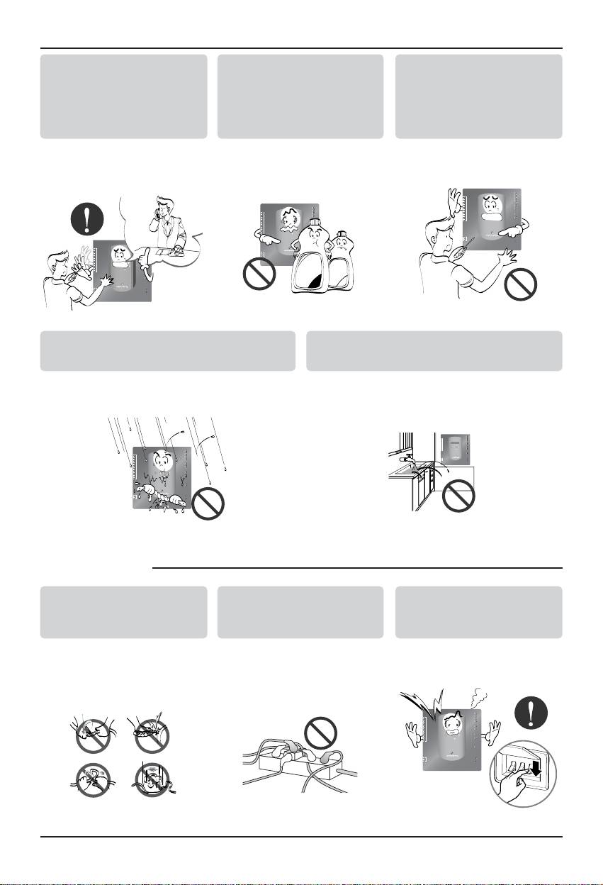
While re-installing the
Do not use the power cord
Do not disjoint randomly
established product, notify
near Flammable gas or
or repair and remodel the
the service center or
combustibles, such as
product.
establishment specialty
gasoline, benzene, thinner,
store.
etc.
• It can cause an accident,
• It may cause an explosion
• It may cause fire and
electric shock, explosion,
or fire
electric shock
injury.shock.
■ During usage
LG-NET 1
TX
RX
1
2
DI
LG-NET 2
TX
LG-NET 3
RX
3
TX
4
LG-NET 4
RX
5
TX
6
RX
7
8
9
10
Ext 1
TX
11
12
Ext 2
RX
TX
RX
13
14
15
16
Ethernet 1
ACT
17
18
MENU/
LNK
19
SELECT
Ethernet 2
ACT
20
LNK
Console
TX
RX
1
2
3
DO
Run
4
Power
LG-NET 1
TX
RX
1
TX
2
DI
LG-NET 2
3
LG-NET 3
RX
TX
4
LG-NET 4
RX
5
TX
6
RX
7
8
9
TX
10
Ext 1
11
Ext 2
RX
TX
12
RX
13
14
15
16
Ethernet 1
ACT
17
18
MENU/
LNK
19
SELECT
Ethernet 2
ACT
20
LNK
Console
TX
RX
1
2
3
DO
Run
4
Power
Thinner
Wax
LG-NET 1
TX
RX
1
2
DI
LG-NET 2
TX
LG-NET 3
RX
3
TX
4
LG-NET 4
RX
5
TX
6
RX
7
8
9
10
Ext 1
TX
11
12
Ext 2
RX
TX
RX
13
14
15
16
Ethernet 1
ACT
17
18
MENU/
LNK
19
SELECT
Ethernet 2
ACT
20
LNK
Console
TX
RX
1
2
3
DO
Run
4
Power
Do not change or extend the
Do not use concert with in
Unplug the unit if strange
conductor at random.
the octopus-like legs way.
sounds, smell, or smoke
comes from it.
• It can cause fire and
• It can cause fire and
• It may cause fire and
electric shock.
electric shock
electric shock accident.
LG-NET 1
TX
RX
1
2
DI
LG-NET 2
TX
LG-NET 3
RX
3
TX
4
LG-NET 4
RX
5
TX
6
RX
7
8
9
10
Ext 1
TX
11
12
Ext 2
RX
TX
RX
13
14
15
16
Ethernet 1
ACT
17
18
SELECT
MENU/
LNK
19
Ethernet 2
ACT
20
LNK
Console
TX
RX
1
2
3
DO
Run
4
Power
Safety Precautions
4 BACnet Gateway
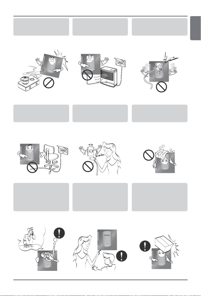
Do not put firearms near
Do not put an electric heater
Do not spill water inside
product.
or conductor near to the
product.
product.
• It can cause fire.
• It can cause fire and
• It can cause electric
electric shock.
shock and breakdown.
2
3
1
D
I
6
4
7
5
8
LG
L
-N
E
T 1
9
T
X
10
R
X
11
1
2
LG
L
G
G
-N
-
N
-N
E
E
T
2
T
3
R
X
TX
1
1
13
4
5
E
T
4
T
TX
X
R
X
X
18
1
6
R
1
1
7
E
xt 1
T
X
20
9
M
E
E
S
xt 2
R
X
E
L
N
U
TX
E
C
/
T
R
X
E
th
e
r
net
1
A
E
C
the
T
r
net
2
L
A
C
LN
T
K
N
K
2
1
C
ons
o
le
4
3
D
O
T
R
X
X
R
Po
u
n
w
e
r
LG-NET 1
TX
RX
1
2
DI
LG-NET 2
TX
LG-NET 3
RX
3
TX
4
LG-NET 4
RX
5
TX
6
RX
7
8
9
10
Ext 1
TX
11
12
Ext 2
RX
TX
RX
13
14
15
16
Ethernet 1
ACT
17
18
MENU/
LNK
19
SELECT
Ethernet 2
ACT
20
LNK
Console
TX
RX
1
2
3
DO
Run
4
Power
LG-NET 1
TX
RX
1
2
DI
LG-NET 2
TX
LG-NET 3
RX
3
TX
4
LG-NET 4
RX
5
TX
6
RX
7
8
9
10
Ext 1
TX
11
12
Ext 2
RX
TX
RX
13
14
15
16
Ethernet 1
ACT
17
18
SELECT
MENU/
LNK
19
Ethernet 2
ACT
20
LNK
Console
TX
RX
1
2
3
DO
Run
4
Power
Do not place heavy goods
Hold the plug by the head of
Do not place heavy goods
on wire.
the power plug when taking
on product.
it out.
• It can cause fire and
• It may cause electric
• It can cause product
electric shock.
shock and damage.
breakdown.
LG-NET 1
TX
RX
1
2
DI
LG-NET 2
TX
LG-NET 3
RX
3
TX
4
LG-NET 4
RX
5
TX
6
RX
7
8
9
10
Ext 1
TX
11
12
Ext 2
RX
TX
RX
13
14
15
16
Ethernet 1
ACT
17
18
MENU/
LNK
19
SELECT
Ethernet 2
ACT
20
LNK
Console
TX
RX
1
2
3
DO
Run
4
Power
LG-NET 1
TX
RX
2
1
DI
LG-NET 2
TX
LG-NET 3
RX
3
TX
4
LG-NET 4
RX
TX
6
5
RX
8
7
10
9
Ext 1
TX
12
11
Ext 2
RX
TX
RX
14
13
16
15
Ethernet 1
ACT
18
17
MENU/
LNK
SELECT
Ethernet 2
ACT
20
19
LNK
Console
TX
RX
2
1
3
DO
Run
4
Power
That increase in case of
Protect the product from
Do not apply shock to
product was been flood
handling by a children.
product.
certainly in the service
center or establishment
specialty store commit .
• I am responsible for fire
• It can cause accident and
• I am responsible for
and electric shock.
product breakdown.
breakdown in case of
shock to product.
LG-NET 1
TX
RX
2
1
DI
LG-NET 2
TX
LG-NET 3
RX
3
TX
4
LG-NET 4
RX
5
TX
6
RX
7
8
9
10
Ext 1
TX
11
12
Ext 2
RX
TX
RX
13
14
15
16
Ethernet 1
ACT
17
18
MENU/
LNK
19
SELECT
Ethernet 2
ACT
20
LNK
Console
TX
RX
1
2
3
DO
Run
4
Power
LG-NET 1
TX
RX
2
1
DI
LG-NET 2
TX
LG-NET 3
RX
3
TX
4
LG-NET 4
RX
TX
6
5
RX
8
7
10
9
Ext 1
TX
12
11
Ext 2
RX
TX
RX
14
13
16
15
Ethernet 1
ACT
18
17
MENU/
LNK
SELECT
Ethernet 2
ACT
20
19
LNK
Console
TX
RX
2
1
3
DO
Run
4
Power
LG-NET 1
TX
RX
1
2
DI
LG-NET 2
TX
LG-NET 3
RX
3
TX
4
LG-NET 4
RX
5
TX
6
RX
7
8
9
10
Ext 1
TX
11
12
Ext 2
RX
TX
RX
13
14
15
16
Ethernet 1
ACT
17
18
MENU/
LNK
19
SELECT
Ethernet 2
ACT
20
LNK
Console
TX
RX
1
2
3
DO
Run
4
Power
Safety Precautions
ENGLISH
Installation/Owner Manual 5
■ During usage
CAUTION
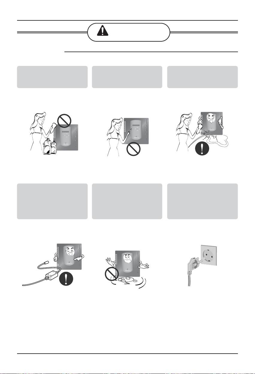
Clean by soft hands using a
Use touch screen with a pen
Do not place any live part on
cleaning material like a soft
that product offers.
the surface having water.
cloth.
• It can result in fire and
• Otherwise, there can be
• It can cause product
product transformation.
breakdown and damage
breakdown.
to the product.
LG-NET 1
TX
RX
2
1
DI
LG-NET 2
TX
RX
TX
4
3
LG-NET 3
RX
TX
6
5
LG-NET 4
RX
8
7
TX
10
9
Ext 1
RX
12
11
Ext 2
TX
RX
14
13
16
15
Ethernet 1
ACT
18
17
SELECT
MENU/
LNK
20
19
Ethernet 2
ACT
LNK
Console
TX
RX
2
1
3
DO
Run
4
Power
T
hinner
Wax
LG-NET 1
TX
RX
2
1
DI
LG-NET 2
TX
LG-NET 3
RX
3
TX
4
LG-NET 4
RX
TX
6
5
RX
8
7
10
9
Ext 1
TX
12
11
Ext 2
RX
TX
RX
14
13
16
15
Ethernet 1
ACT
18
17
SELECT
MENU/
LNK
19
Ethernet 2
ACT
20
LNK
Console
TX
RX
2
1
3
DO
Run
4
Power
LG-NET 1
TX
RX
2
1
DI
LG-NET 2
TX
LG-NET 3
RX
3
TX
4
LG-NET 4
RX
6
5
TX
7
RX
8
10
9
Ext 1
TX
12
11
Ext 2
RX
TX
RX
14
13
16
15
17
MENU/
Ethernet 1
ACT
LNK
18
SELECT
ACT
20
19
Ethernet 2
LNK
Console
TX
RX
2
1
3
DO
Run
4
Power
Use recommended Adapter.
Avoid contact to the metallic
Hold the plug by the head of
goods such as necklace,
the power plug when taking
coin, key, a watch which
it out.
may touch the battery even
for a short-time.
• It may cause product
• It may cause electric
• Otherwise it can result in
breakdown and injury.
shock and damage.
product breakdown
LG-NET 1
TX
RX
2
1
DI
LG-NET 2
TX
LG-NET 3
RX
3
TX
4
LG-NET 4
RX
TX
6
5
RX
8
7
10
9
Ext 1
TX
12
11
Ext 2
RX
TX
RX
14
13
16
15
Ethernet 1
ACT
18
17
MENU/
LNK
SELECT
Ethernet 2
ACT
20
19
LNK
Console
TX
RX
2
1
3
DO
Run
4
Power
LG-NET 1
TX
RX
2
1
DI
LG-NET 2
TX
LG-NET 3
RX
3
TX
4
LG-NET 4
RX
TX
6
5
RX
8
7
10
9
Ext 1
TX
12
11
Ext 2
RX
TX
RX
14
13
16
15
Ethernet 1
ACT
18
17
MENU/
LNK
SELECT
Ethernet 2
ACT
20
19
LNK
Console
TX
RX
2
1
3
DO
Run
4
Power
Safety Precautions
6 BACnet Gateway
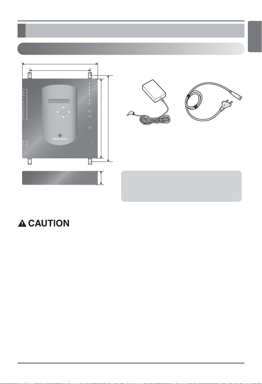
Main features & Specification
273mm
180mm
LG-NET 1
TX
RX
LG-NET 2
TX
1
RX
2
DI
LG-NET 3
TX
3
RX
4
LG-NET 4
TX
5
RX
6
7
8
Ext 1
TX
9
RX
10
Ext 2
TX
11
RX
12
13
14
Ethernet 1
ACT
15
LNK
250mm
273mm
16
17
MENU/
18
SELECT
Ethernet 2
ACT
LNK
19
20
Console
TX
RX
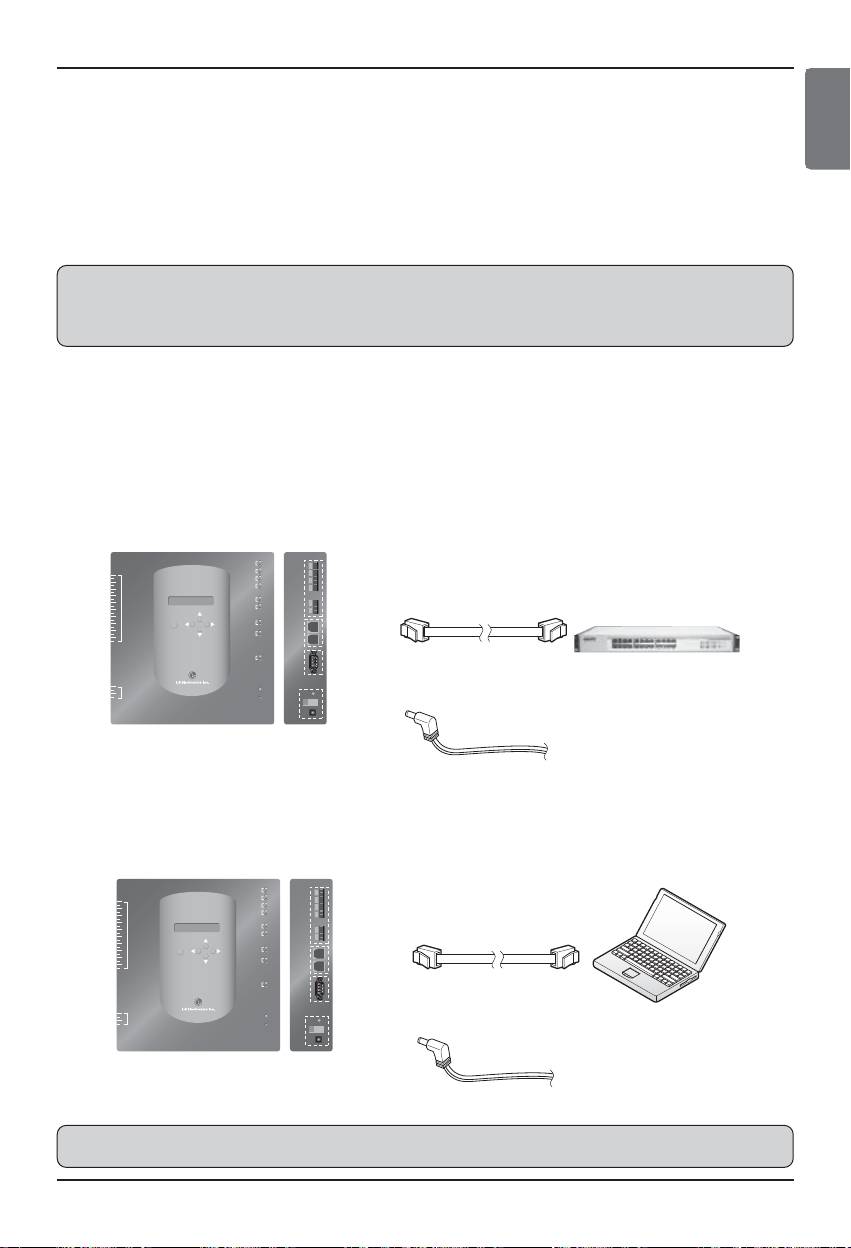
DC adaptor for power supply
Power Cord
1
2
DO
Run
3
Input : 100~240V
250V AC, 3A
4
Power
AC 50/60Hz 1.5A
International
Output : DC 12V
Standard
3.33A, 40W MAX
IEC320 C14 Type
57mm
Notice :
In Australia, purchase the power code
BACnet Gateway dimension
from local area.
The power code is not included in the package.
Main features & Specification
ENGLISH
Components
We are not liable for the problem caused by using the adaptor not supplied by us, so do
not use the product not supplied by us. For more information about the applicable product,
contact with the LG system air conditioner supporting division.
Installation/Owner Manual 7
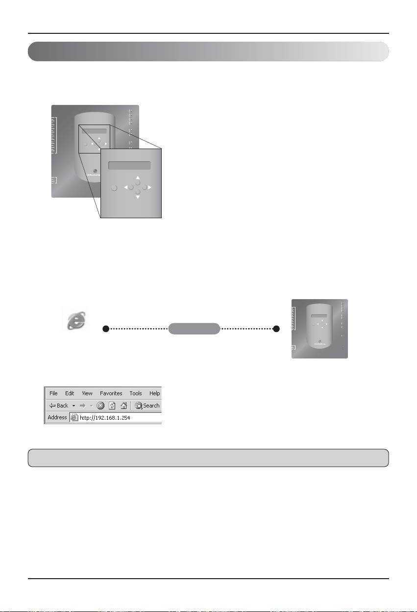
Main features
(1) Environment setup by using the BACnet Gateway button : Network
environment setup
(2) Web server built-in features
Enter the IP address of the BACnet Gateway at the address window by using the Internet
Explorer without installing a separate PC program to access the BACnet Gateway Web Server for
controlling and monitoring the indoor unit/ventilator.
• Controlling 256 air conditioner indoor units and
ventilators at maximum
• Monitoring the error and the operating status
Note: For more information about the detailed features, see the operation section.
LG-NET 1
TX
RX
LG-NET 2
TX
1
RX
2
DI
3
LG-NET 3
TX
RX
4
LG-NET 4
TX
5
RX
6
7
8
TX
9
Ext 1
RX
10
11
Ext 2
TX
RX
12
13
14
15
Ethernet 1
ACT
16
LNK
17
SELECT
MENU/
18
Ethernet 2
ACT
19
LNK
20
Console
TX
RX
1
2
DO
Run
3
4
Power
MENU/
SELECT
LG-NET 1
TX
RX
2
1
LG-NET 2
TX
DI
RX
3
LG-NET 3
TX
4
RX
5
LG-NET 4
TX
6
RX
8
7
9
Ext 1
TX
10
RX
11
Ext 2
TX
12
RX
14
13
ACT
16
15
Ethernet 1
LNK
18
17
MENU/
SELECT
Ethernet 2
ACT
LNK
20
19
Internet
Console
TX
RX
Internet
Explorer
2
1
3
DO
Run
4
Power
Main features & Specification
8 BACnet Gateway
Main features & Specification
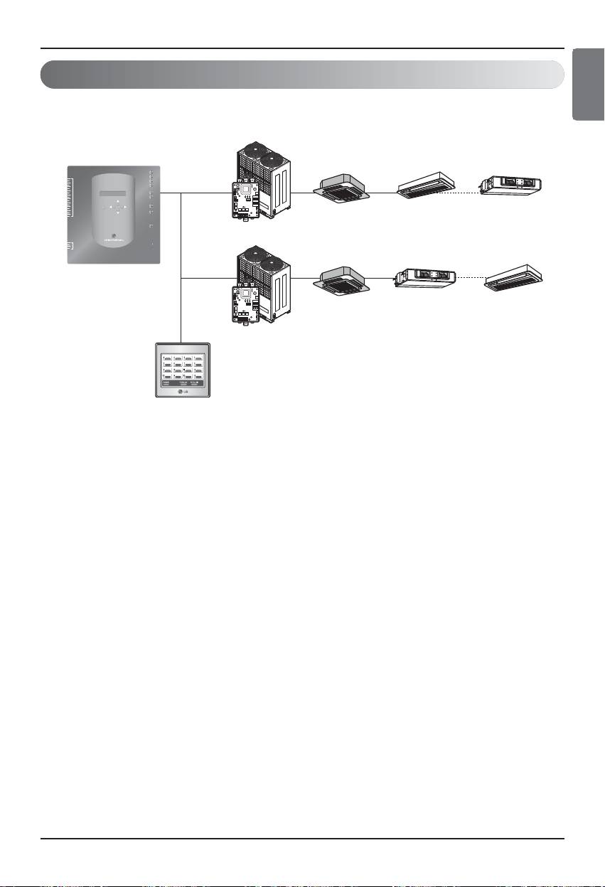
(3) Possible to use together with the simple central controller
It is possible to use the BACnet Gateway by connecting the 16-room simple central controller to
the PI485.
(4) Interlocking Fire feature
The fire is controlled via the extended DI port (DI Port 4). When a fire breaks out, all indoor units
and ventilators on the LG-net are turned off.
Multi V
LG-NET 1
TX
RX
LG-NET 2
TX
2
1
DI
RX
TX
RX
4
3
LG-NET 3
LG-NET 4
RX
6
5
TX
8
7
TX
10
9
Ext 1
RX
Ext 2
TX
12
11
RX
ON
L1 2 3 4
KSDO4H
14
13
16
15
Ethernet 1
ACT
LNK
PI485
18
17
MENU/
19
SELECT
Ethernet 2
ACT
LNK
.......................
20
(0.0) (0.1)
(0.F)
Console
TX
RX
Central control
address
2
1
DO
Run
4
3
Power
........
Multi V
BACnet Gateway
ON
L1 2 3 4
KSDO4H
PI485
(F.0) (F.1)
.......................
(F.F)
Central control
address
Simple central controller
Main features & Specification
ENGLISH
Installation/Owner Manual 9

Main features & Specification
Specification (hardware)
1. CPU: PXA256-400MHz Xscale
2. RAM: 128MB (32 x 4) SDRAM
3. ROM: 512KB NOR Flash – Boot image
128MB (64 x 2) NAND Flash – Program image, database, etc.
4. RS-232 Console : For updating (developing) the program
5. Communication port
• RS-485 port : PI485 communication port 4EA (connecting the air conditioner and the ventilator),
RS-485 port 2EA for connecting the outdoor unit (reserved)
• RS-232 communication port : Port 1EA for upgrading the program
• LAN port : 1EA for the Internet connection (Ethernet 10Base-T Ethernet)
1EA for reserved
6. External input port: 20EA (Pulse countable, DC 12V) extended to the external
External output port : Digital output x 4EA (Relay output, 5V) – DO2~4 : reserved
7. LED: 20EA (RS-485 communication status display / Ethernet communication status display /
RS-232 communication status display / Power & operation status display)
8. LCD : 16 x 2 character
IP address setup and Network environment & information display
Note: This product conforms to the GPL (General Public License) for using the Embedded Linux.
10 BACnet Gateway
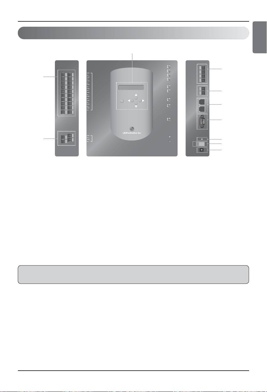
Denomination for each component
Note: It is possible to freely start or stop the indoor unit for corresponding to High or Low signal of
each external input signal.
1
LG-NET 1
TX
RX
LG-NET 2
TX
2
1
RX
2
DI
LG-NET 3
TX
RX
9
3
4
LG-NET 4
TX
5
RX
6
7
8
Ext 1
TX
9
RX
10
Ext 2
TX
11
RX
3
12
13
14
Ethernet 1
ACT
15
LNK
16
17
MENU/
SELECT
Ethernet 2
ACT
18
4
LNK
19
20
Console
TX
RX
5
1
2
DO
Run
10
3
6
4
Power
7
8
Front Right sideLeft side
1. Button & LCD for setting the network environment and displaying the display
2. RS-485 communication port (4EA) for connecting the Air conditioner/Ventilator PI485
3. RS-485 communication terminal (reserved) for the external extension
5. RS-232 port : for updating the program
6. Reset switch : Software reset switch
7. Power On/Off switch
8. DC12V adaptor connection terminal
9. Terminals (20 ports) for connecting the external input signal - DC 0~24V input terminal
10. Terminals(4 port) for connecting the external ouput signal : port # 1 ➝ fire interlocking ,
others ➝ reserved
Main features & Specification
ENGLISH
Installation/Owner Manual 11
How to install
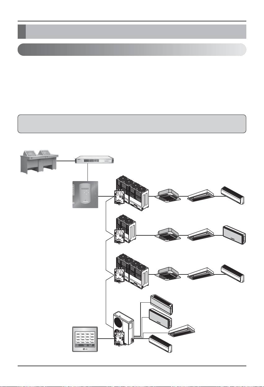
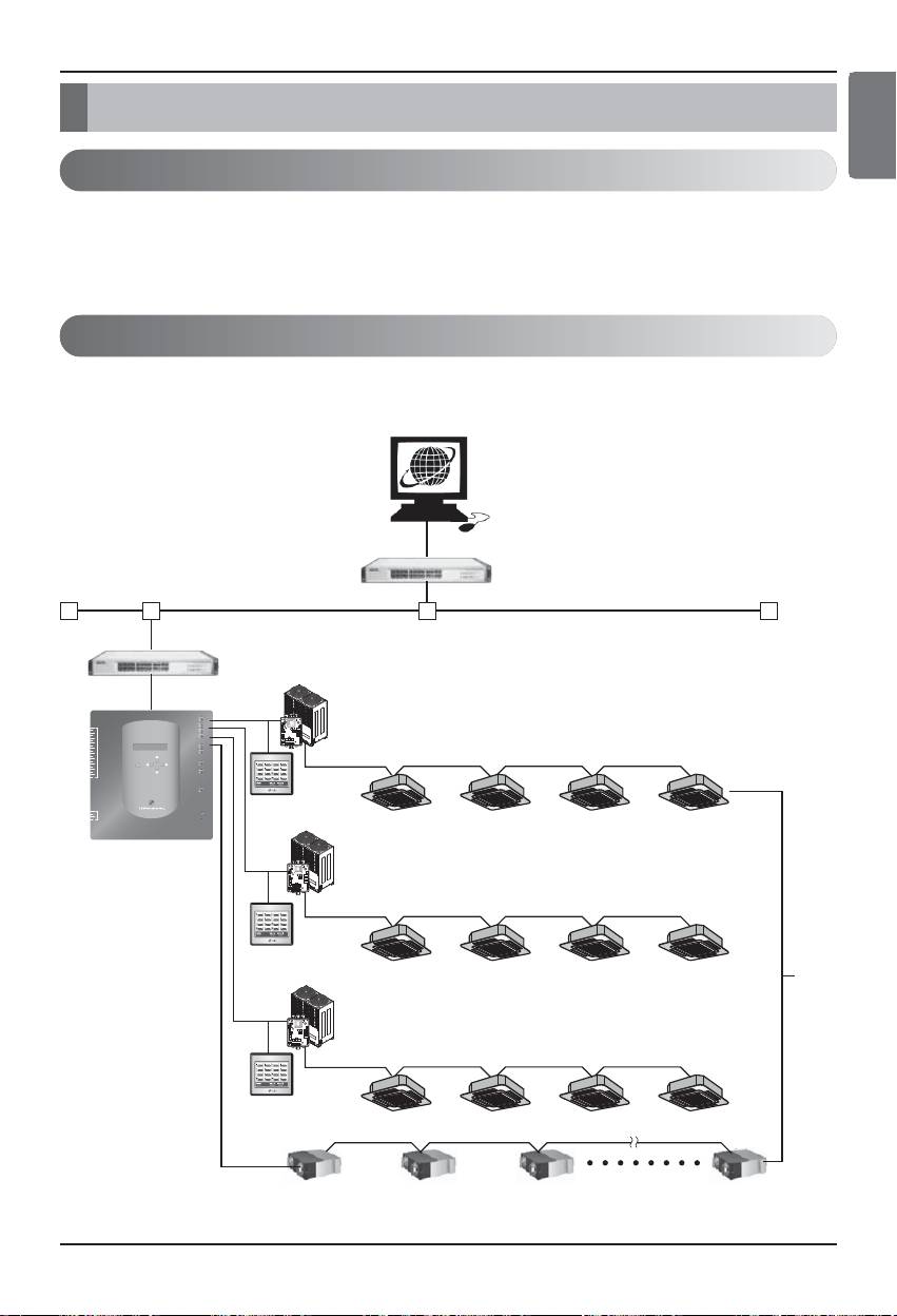
System diagram
Installation specification
• 256 indoor units at maximum / 1 BACnet Gateway
• Total 256 units(Indoor unit/Vent/DXHRV/AHU) at maximum / 1 BACnet Gateway
• RS-485 ports 4 / 1 BACnet Gateway
• 64 PI485 units at maximum / 1 RS-485 port
• 256 indoor units at maximum / 1 RS-485 port. We recommend to connect them divided into 4 ports
for improving the communication performance.
Note: However, when it should be necessary to change the above specification, contact to the LG
System Air Conditioner supporting division.
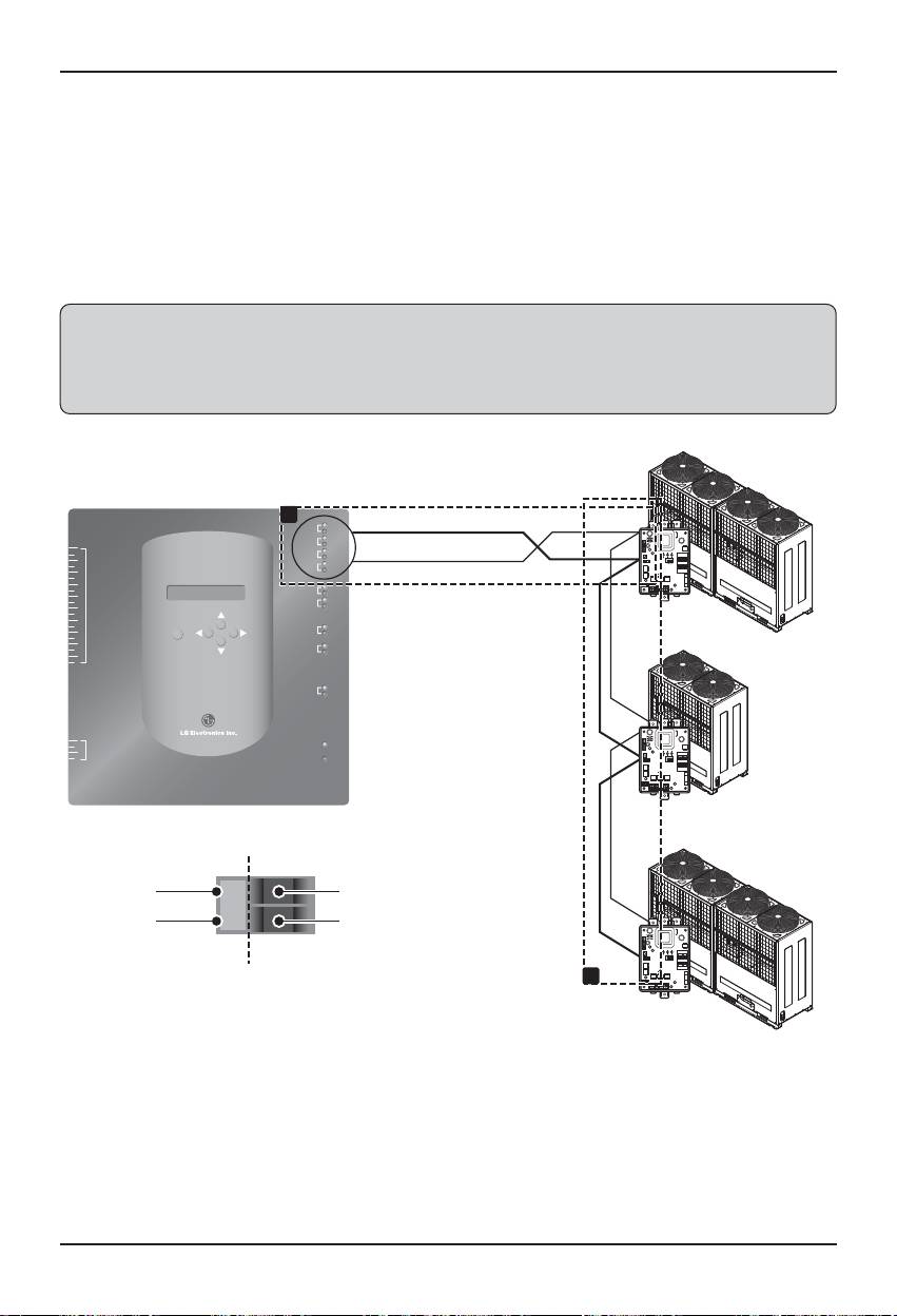
(1) When connecting the BMS by using one BACnet Gateway
Hub
LAN
(direct cable)
BMS
Multi V
LG-NET 1
TX
RX
........
(Building
1
2
3
DI
LG-NET 2
TX
LG-NET 3
RX
TX
RX
00 01
0F
4
5
LG-NET 4
TX
6
RX
7
8
9
10
Ext 1
TX
RX
Management
11
12
Ext 2
TX
RX
13
14
15
16
Ethernet 1
ACT
17
MENU/
LNK
18
19
SELECT
Ethernet 2
ACT
System)
20
LNK
Console
TX
ON
RX
L1 2 3 4
KSDO4H
1
2
3
DO
Run
4
Power
PI485
BACnet Gateway
Multi V
........
10 11 1F
ON
L1 2 3 4
KSDO4H
PI485
Multi V
........
20
21 2F
ON
L1 2 3 4
KSDO4H
PI485
........
F0
Multi
F1
F2
ON
L1 2 3 4
KSDO4H
F3
PI485
Simple central controller
(possible to connect if necessary)
How to install
12 BACnet Gateway
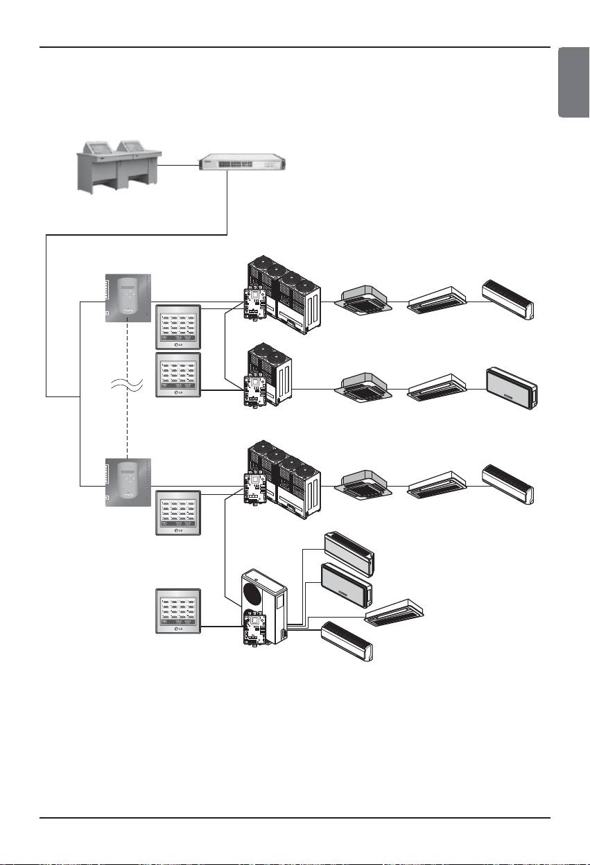
(2) When connecting the BMS by using more than one BACnet
Gateway (possible to connect 16 units at maximum)
Hub
LAN
(direct cable)
BMS(Building Management System)
BACnet Gateway
Multi V
TX
00 01
. . .
LG-NET 1
RX
0F
1
2
LG-NET 2
TX
3
RX
4
DI
LG-NET 3
TX
5
LG-NET 4
RX
6
TX
7
RX
8
9
10
Ext 1
TX
11
RX
12
Ext 2
TX
13
RX
14
15
16
Ethernet 1
ACT
17
18
19
20
SELECT
MENU/
Ethernet 2
LNK
ACT
LNK
Console
TX
RX
ON
L1 2 3 4
KSDO4H
1
2
3
4
DO
Power
Run
PI485
Multi V
. . .
10 11 1F
ON
L1 2 3 4
KSDO4H
Simple central
controller
PI485
(possible to connect
if necessary)
Multi V
. . .
LG-NET 1
TX
LG-NET 2
RX
00
01 2F
1
2
3
DI
LG-NET 3
TX
RX
4
TX
5
RX
6
LG-NET 4
TX
7
RX
8
9
10
Ext 1
TX
11
RX
12
Ext 2
TX
13
RX
14
15
16
ACT
17
Ethernet 1
LNK
18
19
MENU/
ACT
20
SELECT
Ethernet 2
LNK
Console
TX
RX
ON
L1 2 3 4
KSDO4H
1
2
3
4
DO
Power
Run
BACnet Gateway
PI485
. . .
F0
Multi
F1
F2
ON
L1 2 3 4
KSDO4H
Simple central
F3
controller
PI485
(possible to connect
if necessary)
How to install
ENGLISH
Installation/Owner Manual 13

How to install
Installation Order
(1) Installing the hardware
■ Setting the indoor unit
Set the unique address for all indoor units connected to the BACnet Gateway.
Two hexadecimal digits 00~FF can be set to the address. The address can be set by the wired or
wireless remote controller.
■ Installing the PI485
Install one PI485 for each outdoor unit and install the Dip switch correctly. Check the red LED
blinking as many as the number of the indoor units.
■ Connecting the PI485-BACnet Gateway
Connect the PI485 A and B terminals of each outdoor unit to the RS-485 port of the BACnet
Gateway.
■ Connecting the BACnet Gateway to the Internet
Connect the BACnet Gateway to the hub (Internet) or the PC via the LAN cable. And then, apply
the power to the BACnet Gateway.
(2) Installing the software
■ How to set the BACnet Gateway
Set the BACnet Gateway by using the button and the LCD display.
■ Network environment setup of the BACnet Gateway
After getting the IP address of the BACnet Gateway assigned by the network administrator, set the
network environment such as IP address of BACnet Gateway by using the button of the BACnet
Gateway.
(3) Checking the installation
After installing the BACnet Gateway, it is possible to check the product communication status by
using the Web controlling/monitoring feature.
14 BACnet Gateway
Hardware Installation
(1) Setting the indoor unit address
• By considering the entire installation configuration connecting to one BACnet Gateway, set the
unique address for each indoor unit. (We recommend to reflect it to the installation drawing.)
• Two hexadecimal digits 00~FF can be set to the address of the indoor unit.
• For the Multi V product, in order to identify the system component, we recommend to set the outdoor
unit number to the first digit of the address and the indoor unit number to the second digit.
• The ventilating product can be also installed and controlled by the BACnet Gateway.
(However, the address of the ventilation product cannot be set to overlap the address of the air
conditioner.)
Indoor unit numberOutdoor unit number
00
Multi V
LG-NET 1
TX
RX
. . .
1
2
3
DI
LG-NET 2
TX
RX
TX
00
01
0F
4
LG-NET 3
5
LG-NET 4
RX
TX
6
RX
7
8
9
TX
10
Ext 1
RX
11
Ext 2
TX
12
RX
13
14
15
16
Ethernet 1
ACT
17
18
MENU/
LNK
19
SELECT
Ethernet 2
ACT
20
LNK
Console
TX
ON
RX
L1 2 3 4
KSDO4H
1
2
3
DO
Run
4
Power
PI485
BACnet Gateway
Multi V
. . .
10 11 1F
ON
L1 2 3 4
KSDO4H
PI485
Multi V
. . .
20
21 2F
ON
L1 2 3 4
KSDO4H
PI485
. . .
F0
Multi
F1
F2
ON
L1 2 3 4
KSDO4H
F3
PI485
How to install
ENGLISH
Installation/Owner Manual 15
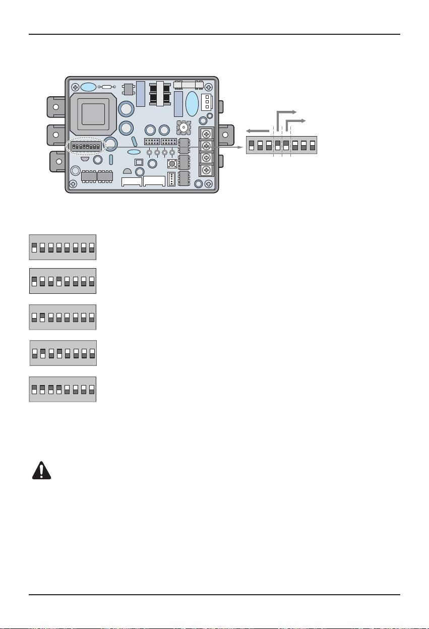
(2) Installation PI485
Select Air
Select Network Type
Conditioer Type
Select Advanced Control Type
ON
KSDO4H
L1 2 3 4
ON
ON
ON
ON
ON
How to install
* LGAP : LG Air conditioner Protocol
Multi V & Multi(LGAP applied) products Configuration Methods
➔ 1 ON, All others OFF: Multi V products(Except CRUN products) or
Multi(Non-Inverter) Product applied Common PCB(Refer to NOTE) or
Multi(Inverter) Product + Central Controller(All types) - Without LGAP
➔ 1 and 4 ON, All others OFF: Multi V products(Except CRUN prod-
ucts) or Multi(Non-Inverter) Product applied Common PCB or
Multi(Inverter) Product + Central Controller(All types) - Using LGAP
➔ 2 ON, All others OFF: Multi(Non-Inverter) Product
+ Centroller(All types) - Without LGAP
➔ 2 and 4 ON, All others OFF: Multi Non-Inverter Product
+ Central Controller(All Types) - Using LGAP
➔ 1,2,3,4 ON : Multi V CRUN Product
+ Central Controller(All types) - Using LGAP
* Please refer the corresponding Central Controller installation manual if you want to know whether
your Central Controller is compatible with LGAP or not.
CAUTION:
The wrong setting of air-conditioner switch could cause malfunctioning.
Switch setting must be done carefully.
Push the Reset button after changing the Dip switch.
NOTE: Multi(Non-Inverter) Product applied Common PCB
PCB P/NO. : 6871A20917*
P/NO. : 6871A20918*
P/NO. : 6871A20910*
16 BACnet Gateway
ON
ON
ON
How to install
ENGLISH
- To use the advanced lock function (Run Mode lock, Fan Speed lock,
Temperature Lock, and Temperature Range lock; adjustable only within certain boundary)
by central controller, Set up the fifth dip switch according to the type of outdoor product.
- In case of advanced lock function, it can use only the central controller applied to LGAP.
➔ 1, 4 and 5 ON, All others OFF :
MultiV Products (Except CRUN products) or MPS Inverter Product
+ Central Controller (All types) - Using LGAP
➔ 2, 4 and 5 ON, All others OFF :
Multi Standard Product + Central Controller (All types) - Using LGAP
➔ 1, 2, 3, 4and 5 ON, All others OFF :
MultiV CRUN Product + Central Controller (All types) - Using LGAP
NOTE : The advanced lock setting
Some products do not support advanced lock function.
In this case, The fifth dip switch on PI485 must be on.
In case of product applied to advanced function, it can process the advanced lock function without fifth dip
switch ON.
If all units support advanced lock function,
It is recommended that the fifth dip switch be off, so that advanced lock function is processed faster.
CAUTION:
The wrong setting of air-conditioner switch could cause malfunctioning.
Switch setting must be done carefully.
After setting the dip switch, PI485 must be reset
Installation/Owner Manual 17
How to install
(3) Connecting PI485 – BACnet Gateway
1. When connecting two or more PI485s to one BACnet Gateway, connect each BUS-A/BUS-B of
other PI485s to be connected to BUS-A/BUS-B of the PI485.
2. Connect the BUS-A of the PI485 to the TX of the BACnet Gateway and the BUS-B to the RX.
• Connect LG-NET 1~4 to any of the BACnet Gateway. (Connect the LG-NET to the RS-485 port)
• 64 outdoor units at maximum can be connected to each 485 port of the BACnet Gateway and the
number of indoor units to be connected to the BACnet Gateway is 256 at maximum.
Note: Disconnect the connector from the 485 port of the BACnet Gateway, connect the BUS-A to
the TX and the BUS-B to the RX by using the (-) driver, and then connect the connector to the
485 port of the BACnet Gateway. Because the 485 communication line has a polarity, connect
the line correctly.
18 BACnet Gateway
Multi V
1
LG-NET 1
TX
TX
RX
LG-NET 2
TX
1
RX
2
DI
LG-NET 3
TX
RX
3
RX
ON
TX
L1 2 3 4
KSDO4H
4
LG-NET 4
5
RX
6
7
8
Ext 1
TX
9
RX
2
10
Ext 2
TX
RX
Shield line of 0.75 mm
11
’
12
13
14
ACT
(RS-485 communication line)
PI485
15
Ethernet 1
LNK
16
17
MENU/
18
SELECT
Ethernet 2
ACT
LNK
19
20
Multi V
Console
TX
RX
1
2
DO
Run
3
4
Power
ON
L1 2 3 4
KSDO4H
BACnet Gateway side PI485 side
Multi V
BUS-ATX
RX
BUS-B
ON
L1 2 3 4
KSDO4H
2
PI485
PI485
PI485
PI485
PI485
PI485
How to install
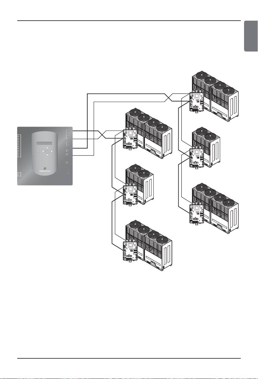
• If there are many outdoor units, distribute the lines to LG-NET 1~4 to improve the control speed.
[Example for distributing the lines to LG-NET 1 and LG-NET 2]
Installation/Owner Manual 19
Multi V
ON
L1 2 3 4
KSDO4H
Multi V
PI485
TX
Multi V
RX
BUS-A
ON
L1 2 3 4
KSDO4H
TX
RX
PI485
ON
L1 2 3 4
KSDO4H
Multi V
PI485
Multi V
ON
L1 2 3 4
KSDO4H
PI485
ON
L1 2 3 4
KSDO4H
Multi V
PI485
ON
L1 2 3 4
KSDO4H
PI485
BUS-A
BUS-A
BUS-B
BUS-A
BUS-A
BUS-B
BUS-A
LG-NET 1
TX
RX
LG-NET 2
TX
1
RX
2
DI
LG-NET 3
TX
3
RX
4
5
LG-NET 4
TX
RX
6
7
8
9
Ext 1
TX
RX
10
Ext 2
TX
11
RX
12
13
14
15
Ethernet 1
ACT
16
LNK
17
MENU/
18
SELECT
Ethernet 2
ACT
19
LNK
20
Console
TX
RX
1
2
DO
Run
3
4
Power
ENGLISH
How to install
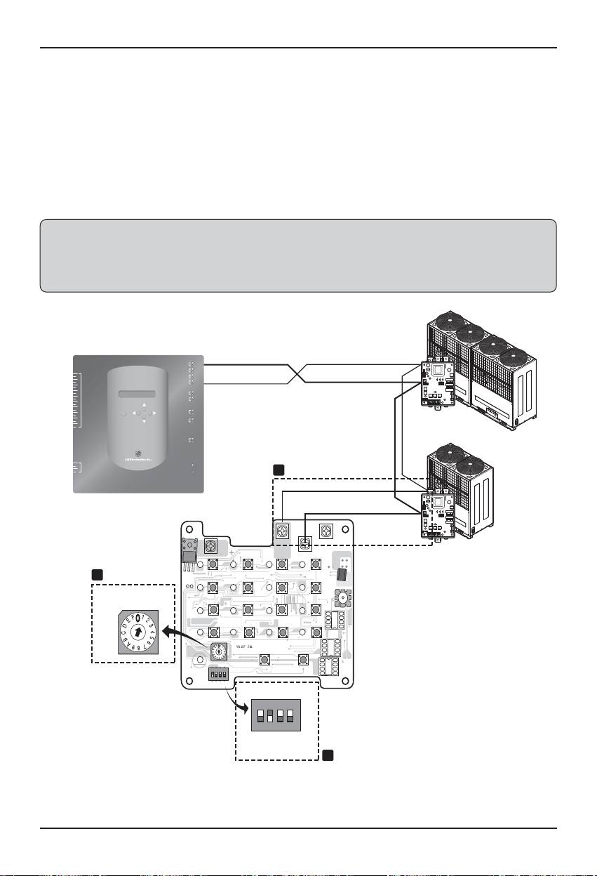
• When using the simple central controller with the BACnet Gateway
1. Connect the BUS-A and the BUS-B of the PI485 to C and D of the simple central controller.
2. Set the rotary switch of the simple central controller to match with the group number of the indoor
unit to control.
3. Set the dip switch number 1 of the simple central controller to Off as slave and set the dip switch
number 2 to On as LGAP use mode.
Note: Check the LGAP label at the right side of the case of the simple central controller.
Only the product with the label can be connected to the BACnet Gateway at the same time.
Connect the VCC and the GND of the simple central controller from the P1485 or separately to
the adaptor. (See the manual for the simple central controller.)
Multi V
BUS-B
TX
TX
LG-NET 1
RX
LG-NET 2
TX
1
RX
2
DI
LG-NET 3
TX
3
RX
BUS-A
4
LG-NET 4
TX
RX
RX
ON
KSDO4H
5
L1 2 3 4
6
7
8
Ext 1
TX
9
RX
10
Ext 2
TX
11
RX
2
12
13
Shield line of 0.75 mm
14
15
Ethernet 1
ACT
16
LNK
’
17
MENU/
18
SELECT
Ethernet 2
ACT
19
LNK
(RS-485 communication line)
20
PI485
Console
TX
RX
1
Multi V
2
DO
Run
3
4
Power
1
ON
L1 2 3 4
KSDO4H
CN-POWER
GND
CN-COM B
CN-POWER
CN-COM A
S1
S2
L
S4
PI485
LED2
LED3
LED4
2
IC1P
S5
+
+
S6
+
+
S3
+
LED5
LED7
LED8
TX1
Rotary switch
S9
S10
S11
S12
+
+
+
Simple central controller
LED9
LED10
LED11
LED12
+
+
S14
+
S15
+
S16
LED13
LED14
LED15
LED16
PWB:6870A10001A
ASM:6711A20005E
+
S15
S18
LED17
ON
KSDO4H
L1 2 3 4
Ex)When controlling
S19
the indoor Unit 10~1F,
ON
KSDO4H
setting the switch to 1.
L1 2 3 4
DIP switch
3
20 BACnet Gateway
How to install
(4) Connecting Internet – BACnet Gateway
• In the case connecting a BACnet Gateway to the internet which is already installed in the site, there
should be a HUB which is already installed.
In the case, being able to inter-work with the BMS system using the internet and connecting a
BACnet Gateway to the internet which is already installed in the site : Use the HUB
Note: Through the test operation of BACnet Gateway, it can be judged whether the installation is
properly done or not (instead of using the HUB, connecting the BACnet Gateway with a cross
cable)
• Be aware the type of the cable youʼre using (the Direct cable or the Cross cable)
• Prior to the Connecting, Check whether the cable works properly or not through the LAN tester.
• After applying the power to the DC adapter provided, Turn on the power switch.
■ In the case using HUB
Use a LAN cable (Direct cable) and connect it to Ethenet1 of the BACnet Gateway
(Ethernet2 is reserved in case)
■ In the case NOT using HUB
(to check the communication status using web control/monitoring function in the site)
Use a LAN cable (Cross cable) and connect it to Ethenet1 of the BACnet Gateway
(Ethernet2 is reserved in case)
Note: If know Detail web control/monitoring function, refer web control/monitoring part
LG-NET 1
TX
RX
LG-NET 2
TX
RX
2
1
DI
LG-NET 3
TX
RX
RS-485 port
4
3
TX
5
LG-NET 4
RX
6
8
7
Ext 1
TX
RX
10
9
Ext 2
TX
RX
Ethernet 1
12
11
14
13
16
15
Ethernet 1
ACT
LNK
18
17
SELECT
MENU/
Ethernet 2
ACT
19
LNK
Ethernet port
20
Console
TX
RX
LAN Cable(Direct Cable)
Console port
Hub
2
1
DO
Run
4
3
Power
Power switch
& power port
LG-NET 1
TX
RX
LG-NET 2
TX
1
RX
2
DI
3
LG-NET 3
TX
RX
RS-485 port
4
TX
6
5
LG-NET 4
RX
8
7
TX
10
9
Ext 1
RX
TX
12
11
Ext 2
RX
Ethernet 1
14
13
Ethernet 1
16
15
ACT
LNK
18
17
SELECT
MENU/
Ethernet 2
ACT
19
LNK
Ethernet port
20
Console
TX
RX
LAN Cable(Cross Cable)
Console port
2
1
DO
Run
4
3
Power
Power switch
& power port
Connect DC Adaptor
ENGLISH
Installation/Owner Manual 21
How to install
Software Installation
(1) How to set the BACnet Gateway
The following information should be set to use the BACnet Gateway
• BACnet Gateway network environment Setting IP address, Gateway address and Net mask address
■ Setup Order
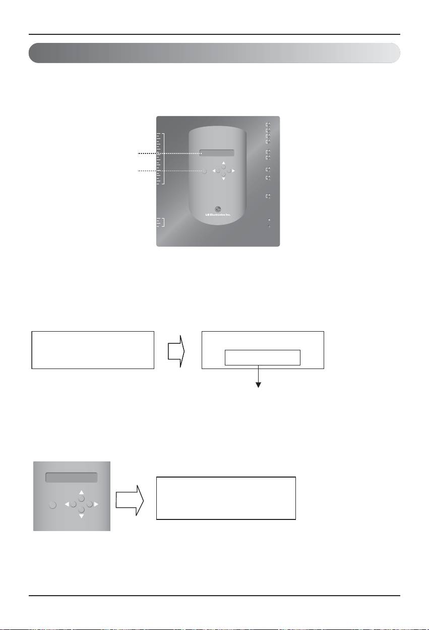
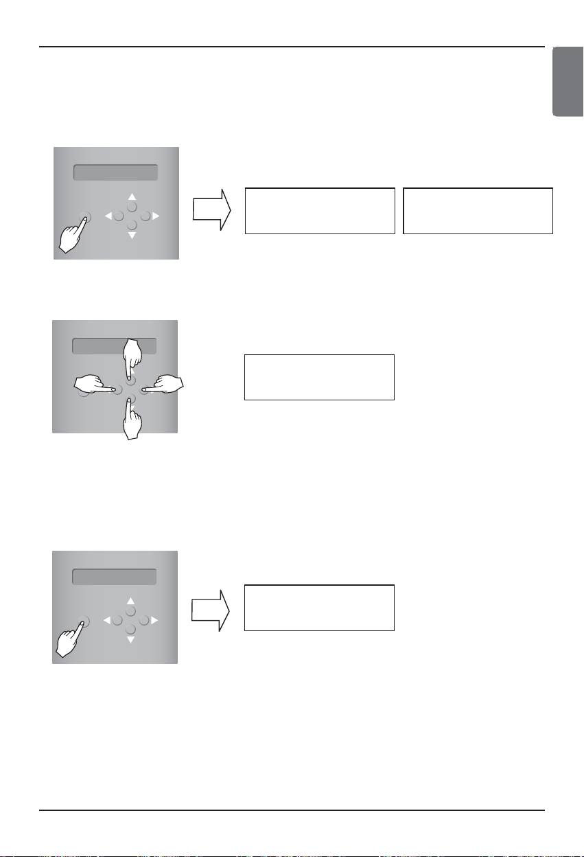
1. Turn on the BACnet Gateway.
(The following screen will be displayed on the BACnet Gateway LCD screen about 5 seconds after
the power is turned on.)
[LCD screen] [Start-up screen]
• S/W Ver. No. may be different
according to the manufactured date.
2.Press “MENU/SELECT” button of the BACnet Gateway to enter the environment setup mode.
• Menu selection displayed on the screen.
When the "MENU/SELECT" button is pressed
for the first time.
Select "Setting" mode to change setup. Select
"Information" mode to confirm setup state.
LG-NET 1
TX
RX
LG-NET 2
TX
1
RX
2
DI
LG-NET 3
TX
3
RX
4
LG-NET 4
TX
5
RX
6
7
8
Ext 1
TX
LCD Display
9
RX
10
Ext 2
TX
11
RX
12
13
14
ACT
15
Ethernet 1
LNK
BACnet Gateway Button
16
17
MENU/
ACT
18
SELECT
Ethernet 2
LNK
19
20
Console
TX
RX
1
2
DO
Run
3
4
Power
BACnet Gateway
LG Electronics
wait for booting
SW Ver.1.0.0
MENU/
SELECT
Setting
Information
22 BACnet Gateway
How to install
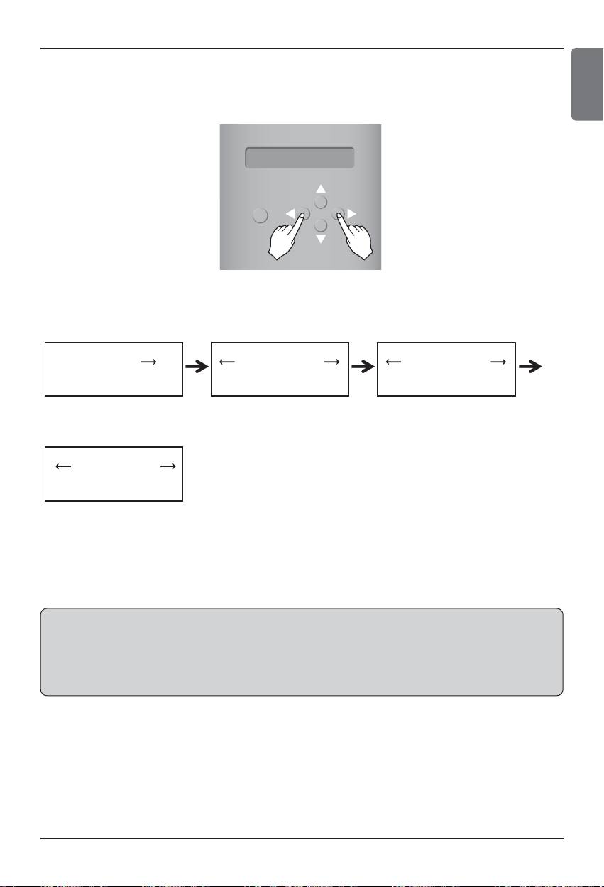
3. After selection "Setting" mode using the up/down(▲, ▼) button, use the left/right(◀, ▶) button to
select the desired function.
Enter the IP address Enter the Gateway address Enter the Net mask
Enter the Set BACnet Type
4. Press the “MENU/SELECT” button at the desired function to enter into the setup window for the
said mode.
Note: LG BACnet Gateway support two type Gateway depend on selection type "A" and type " B".
Type "A" support multi device per one IP address and Type " B" support only one device per
one IP address.
After asking BMS engineer about multi device or one device per one IP address, select LG
BACnet Gateway's "Set BACnet Type".
MENU/
SELECT
[MENU]
[MENU]
[MENU]
Set IP address
Set GW address
Set Netmask
[MENU]
Set BACnet Type
ENGLISH
Installation/Owner Manual 23
How to install
(2) Network environment setup of the BACnet Gateway
• After getting the IP address of the BACnet Gateway assigned from the network administrator, use
the button of the BACnet Gateway to set up the IP address and the network environment of the
BACnet Gateway.
■ Setup procedure
• Set the IP address
• Enter the Gateway address
• Enter the net mask
• Enter the Set BACnet Type
• Check the network environment setting
Note: If the above items are not entered, it is impossible to control the BACnet Gateway or it causes
the communication error, so make sure that all of them are correctly entered.
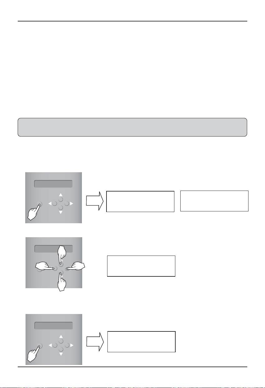
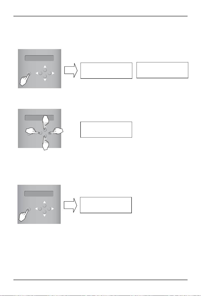
1. Setting the IP address
① First, press the "MENU/SELECT" button of the BACnet Gateway and selecting "Setting" menu.
When the following menu is displayed on the BACnet Gateway LCD screen, press the
“MENU/SELECT” button again to enter the IP address.
② Use the up/down/left/right button (▲,▼,◀,▶) to select the desired address.
③ After entering the last address, press the “MENU/SELECT” button to set the entered address to the
IP address. (When there is no “MENU/SELECT” button input for 5 seconds, the set value is ignored
to return to the existing address.
MENU/
SELECT
[LCD screen]
[MENU]
[Set IP address]
Set IP address
192.168.000.000
MENU/
SELECT
[Example for setting the Gateway address]
[Set IP address]
165.186.002.101
MENU/
SELECT
[LCD screen after completing the setup]
BACnet Gateway
SW ver. 1.0.0
24 BACnet Gateway
How to install
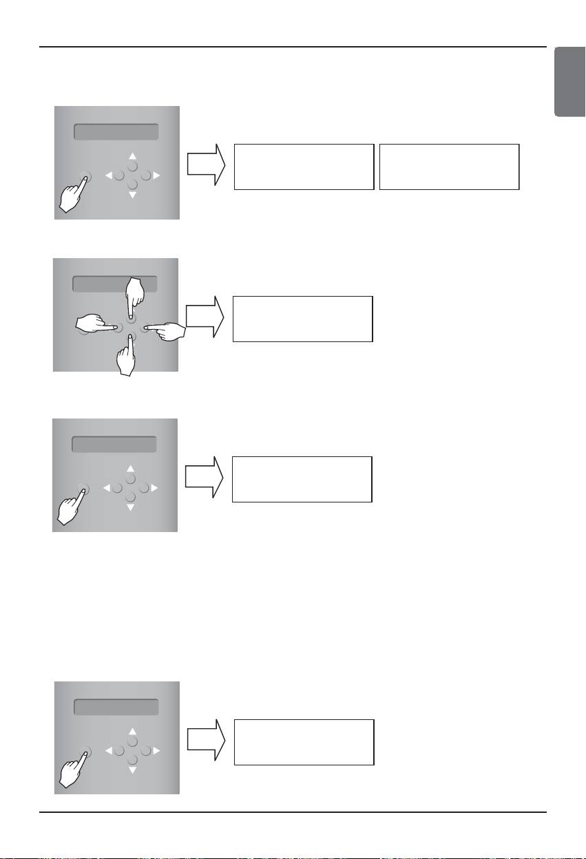
2. Setting the Gateway address
① Press the buttons by the following order. And then, when the following menu is displayed on the
BACnet Gateway LCD screen, press the “MENU/SELECT” button to enter the Gateway address.
② Use the up/down/left/right button (▲,▼,◀,▶) to select the desired address.
3 After entering the last address, press the “MENU/SELECT” button to set the entered address
to the Gateway address.
(When there is no “MENU/SELECT” button input for 5 seconds, the set value is ignored to return to
the existing address.
MENU/
SELECT
[LCD screen]
[MENU]
[Set GW address]
Set GW address
192.168.000.000
MENU/
SELECT
[Example for setting the Gateway address]
[Set GW address]
165.186.002.001
MENU/
SELECT
[LCD screen after completing the setup]
BACnet Gateway
SW ver. 1.0.0
ENGLISH
Installation/Owner Manual 25
How to install
3.Setting the net mask address
① Press the buttons by the following order. And then, when the following menu is displayed on the
BACnet Gateway LCD screen, press the “MENU/SELECT” button to enter the net mask address.
② Use the up/down/left/right button (▲,▼,◀,▶) to select the desired address.
3 After entering the last address, press the “MENU/SELECT” button to set the entered address
to the net mask address. (When there is no “MENU/SELECT” button input for 5 seconds, the
set value is ignored to return to the existing address.
MENU/
SELECT
[LCD screen]
[MENU]
[Set Netmask]
Set Netmask
192.168.000.000
MENU/
SELECT
[Set Netmask]
255.255.255.000
MENU/
SELECT
[LCD screen after completing the setup]
BACnet Gateway
SW ver.1.0.0
26 BACnet Gateway
How to install
4. Setting the Set BACnet Type
① Pres4s the button by the following order. When the following menu is displayed on the BACnet
Gateway LCD screen, press the "MENU/SELECT" button to enter the Set BACnet Type.
② Use the up/down/left/right button (▲,▼,◀,▶) to select the desired BACnet Type.
③ After selecting the BACnet Type, press the "MENU/SELECT" button to set the selected BACnet
Type to the Set BACnet Type.
5. Checking the network environment setting
Press the buttons by the following order. And then, when the following menu is displayed on the
BACnet Gateway LCD screen, press the “MENU/SELECT” button to check the set network
information.
The other information is displayed on the screen every 3 seconds.
(Order to display the information : MAC address → IP address → Gateway address → Net mask
address → Set BACnet Type)
MENU/
SELECT
[LCD screen]
Setting
Information
MENU/
SELECT
[MENU]
[Set BACnet Type]
Set BACnet Type
A ‘
MENU/
SELECT
[Example for setting the gateway Set BACnet Type]
[Set BACnet Type]
A ‘ B
MENU/
SELECT
[LCD screen after completing the setup]
BACnet Gate way
SW ver.1.0.0
ENGLISH
Installation/Owner Manual 27
LGʼs BACnet Gateway Agreement
LGʼs BACnet Gateway Agreement
JMT (Joint Matching Test) – This is necessary for every independent BMS.
The case where a JMT is not necessary is where previously a successful JMT has been carried
out and the BMS system has not been updated by software or hardware changes. In the case
that the BMS has updated their system by either changes, a following JMT will be required.
BNU-BAC Diagnosis – Use of LG's BNU-BAC setup-tool is for confirming the operation/state of
connected A/C units & address ID's, prior to connection with the BMS system.
BMS Engineering – Creating of the Points. This is NOT to be done by LG since it is directly related to
the BMS side. The BMS engineer is to carry out the engineering of the Point, however LG is
responsible for providing the method of how the Points are calculated.
Commission – First step, only using LG's BACnet Gateway, without connecting BMS. This is to be
carried out by LG engineering staff with the use of the BNU-BAC set up tool.
Discrepancy of operation of Gateway by BMS - In the case that the BMS maker feels that the
BACnet Gateway is not functioning correctly via the BACnet Protocol, a test with the use of LG's
BACnet Client software can confirm this. (This test is generally not required)
Hub
BACnetBACnet
LG-NET 1
TX
RX
1
LG-NET 2
TX
2
4
3
DI
RX
LG-NET 3
TX
RX
6
5
LG-NET 4
TX
RX
8
7
9
Ext 1
TX
10
RX
Ext 2
TX
12
11
RX
14
13
16
15
Ethernet 1
ACT
LNK
BACnet Gateway Diagnosis
18
17
MENU/
ACT
20
19
SELECT
Ethernet 2
LNK
Console
TX
RX
2
1
DO
Run
1. Creating of indoor and vent points.
4
3
Power
LG-NET
2. Test of all units and operations.
LG Engineering Side BMS Engineering Side
Note : After the LC BACnet Gateway agreement part, please scrutinize with Companies specialized
in BMS.
28 BACnet Gateway
Test operation procedure
ENGLISH
Test operation procedure
Web control and monitoring
The following procedure is BACnet Gateway test operation for remote control function.
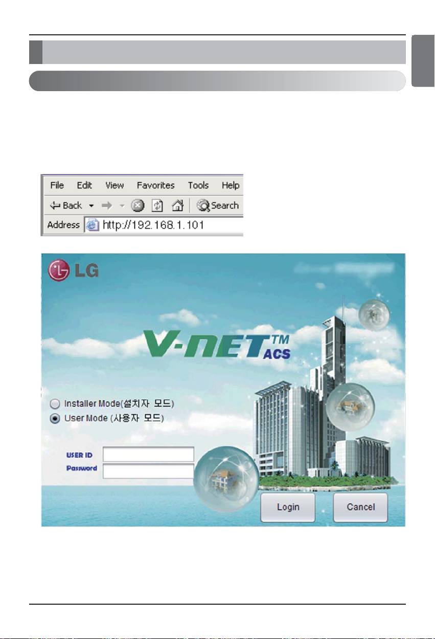
■ Connecting to BACnet Gateway server.
In order to connect to the BACnet Gateway server connect the Ethernet1 (LAN port) in the Gateway
to the PC Input the default IP address on the URL address box for connection.
ID and PW are bacnet, bacnet.
Installation/Owner Manual 29
Test operation procedure
■ Auto address search
The address of the installed indoor unit can automatically be searched.
To search the indoor unit automatically, proceed as follows.
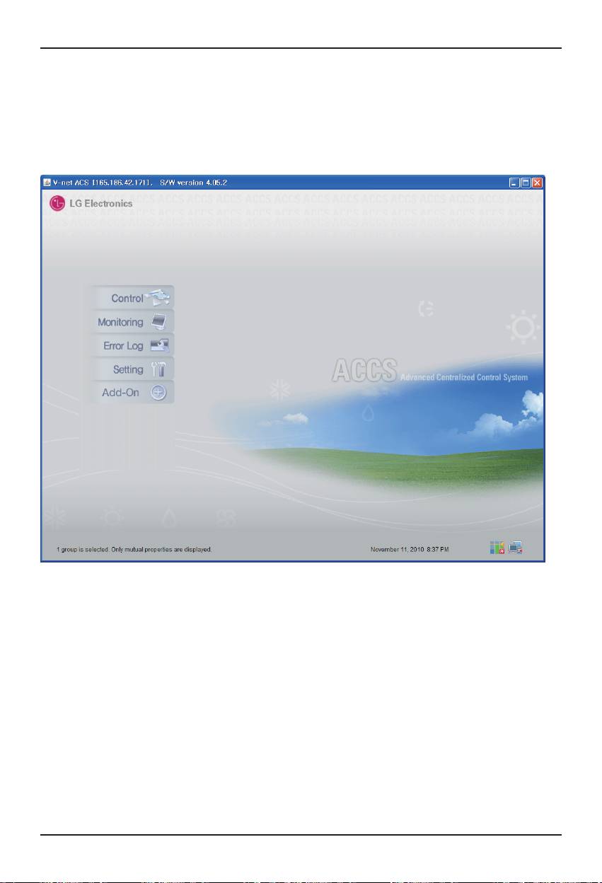
1. When the program is launched normally, the following screen will be displayed.
Click “Setting” menu.
30 BACnet Gateway
Test operation procedure
ENGLISH
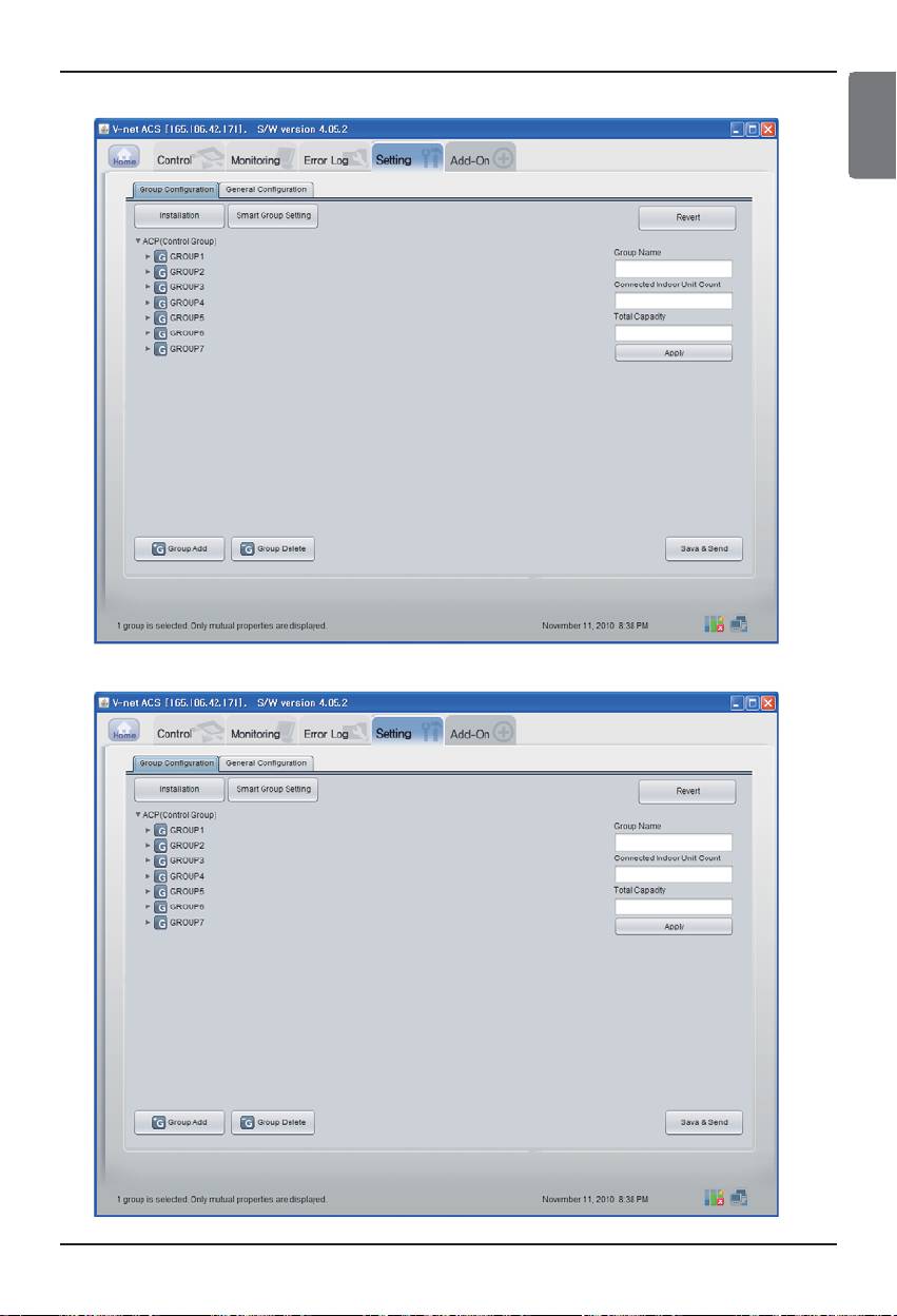
2. As shown below, Setting screen will be appeared
3. Click on ʻInstallationʼ button.
Installation/Owner Manual 31
Test operation procedure
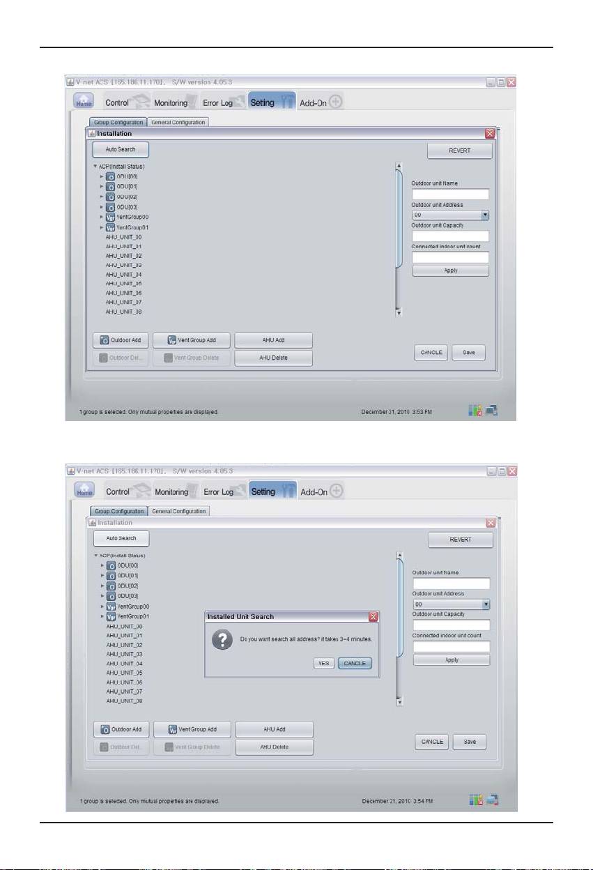
4. Click on ʻAuto searchʼ button.
5. Click on ʻYesʼ button to search the address of the indoor unit.
32 BACnet Gateway
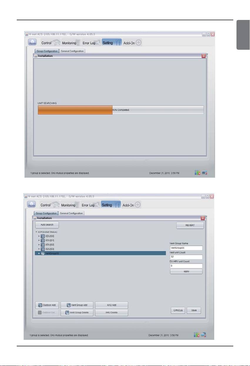
Test operation procedure
ENGLISH
6. Screen when search is in progress.
7. Screen when search is completed. If There is no AHU, go to the step 10.
Installation/Owner Manual 33
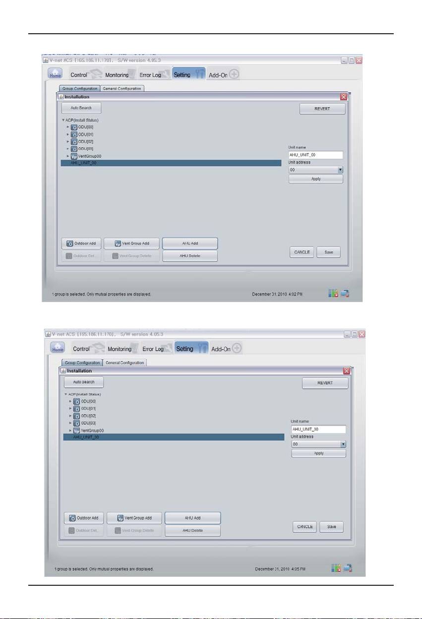
Test operation procedure
8. Click ʻAHU Addʼ button.
9. Click on “Save” button.
34 BACnet Gateway
Test operation procedure
ENGLISH
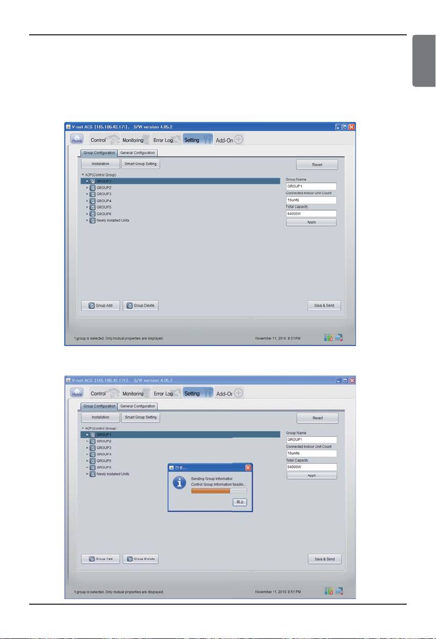
10. As shown below, Setting screen will appear.
1) Click on ʻSmart Group Settingʼ button to automatically create the group based on the
outdoor unit.
2) If you want to move the indoor unit to a different group, click the indoor unit with the
mouse and drag.
3) If you want to rename the group or indoor unit, change the name on the right window and
click on the ʻApplyʼ button.
4) When the group setting is completed, click on the ʻSave & Sendʼ button.
11. When all items are set, click “Save & Send” button to save.
The saving process is performed.
Installation/Owner Manual 35
Test operation procedure
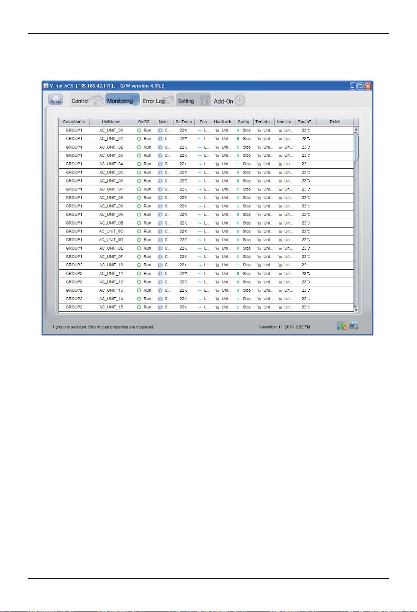
■ Confirmation of monitoring data function
Click the "Monitoring(Indoor Unit/Vent/AHU)" button at the top Remote Diagnosis page, and you
can confirm the information of Indoor Unit/Vent/AHU.
36 BACnet Gateway
Test operation procedure
ENGLISH
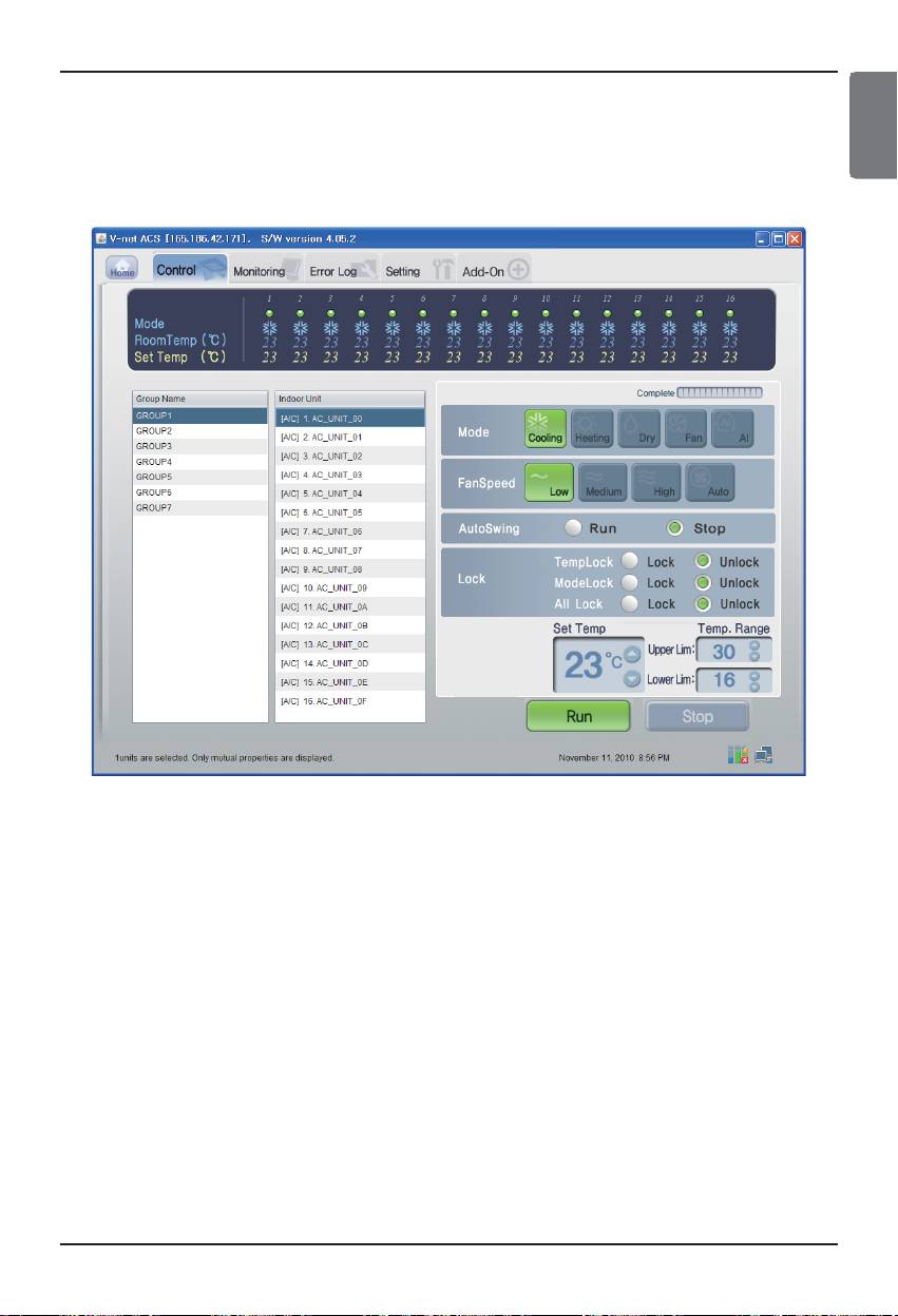
■ Confirmation of Control Function (Indoor Unit/Vent/AHU)
Click the "Control(Indoor Unit/Vent/AHU)" button at the top Remote Diagnosis page, and you can
confirm the data of Indoor Unit/Vent/AHU in real-time.
Installation/Owner Manual 37
Test operation procedure
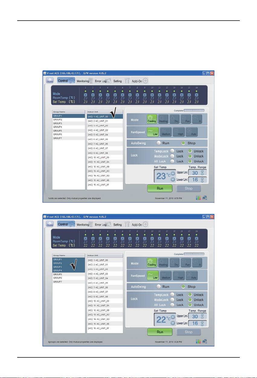
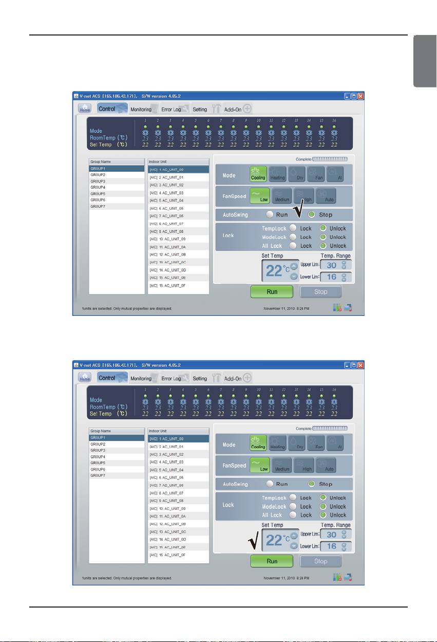
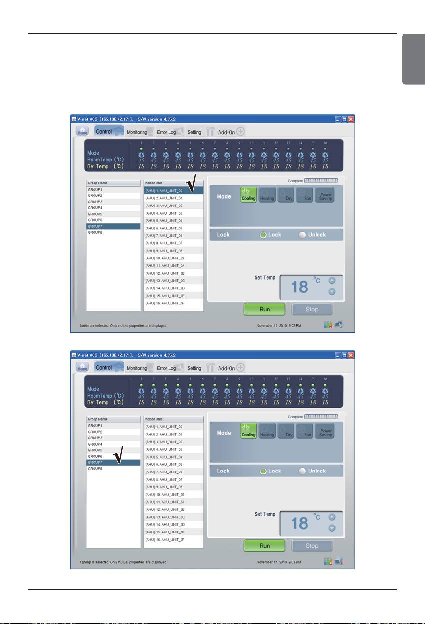
■ Indoor Control
Click the Indoor's Control Group
- Individual / Total Control
Click the unit which will be controlled for individual control or click ALL for total control.
< Individual Control >
< Total Control >
38 BACnet Gateway
Test operation procedure
ENGLISH
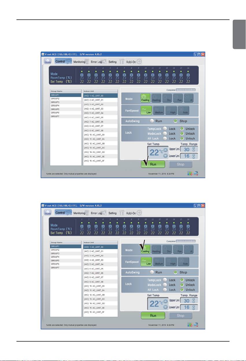
- Control : Run/Stop
(1) Click the Run/Stop button.
< Run/Stop Control >
- Control :Mode
(1) Click the Mode button. (Cooling/Heating/Dry/Fan/AI)
< Mode Control >
Installation/Owner Manual 39
Test operation procedure
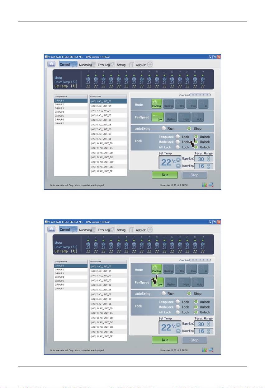
- Control : Lock/Unlock
(1) Select the Lock button. (Temp Lock/Mode Lock/ All Lock)
< Lock/Unlock Control >
- Control : Fan Speed
(1) Click the Fan Speed button. (Low/Medium/High/Auto)
< Fan Speed Control >
40 BACnet Gateway
Test operation procedure
ENGLISH
- Control : Swing
(1) Select the Auto Swing button. (Run/Stop)
< Swing Control >
- Control:Temp.
(1) Click the Up/Down button for Set Temp.
< Temp. Control >
Installation/Owner Manual 41
Test operation procedure
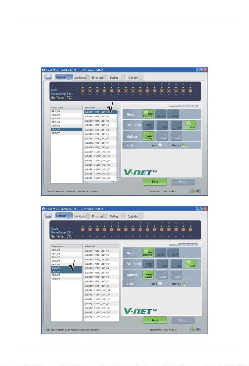
■ Vent Control
Click the Vent Control Group
- Individual Control / Total Control
Click the unit which will be controlled for individual control or Click ALL for total control.
< Individual Control >
< Total Control >
42 BACnet Gateway
Test operation procedure
ENGLISH
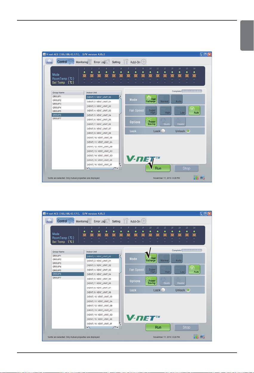
- Control : Run/Stop
(1) Click the Run/Stop button.
< Run/Stop Control >
- Control : Mode
(1) Click the Mode button. (Heat Exchange/Normal/Auto)
< Mode Control >
Installation/Owner Manual 43
Test operation procedure
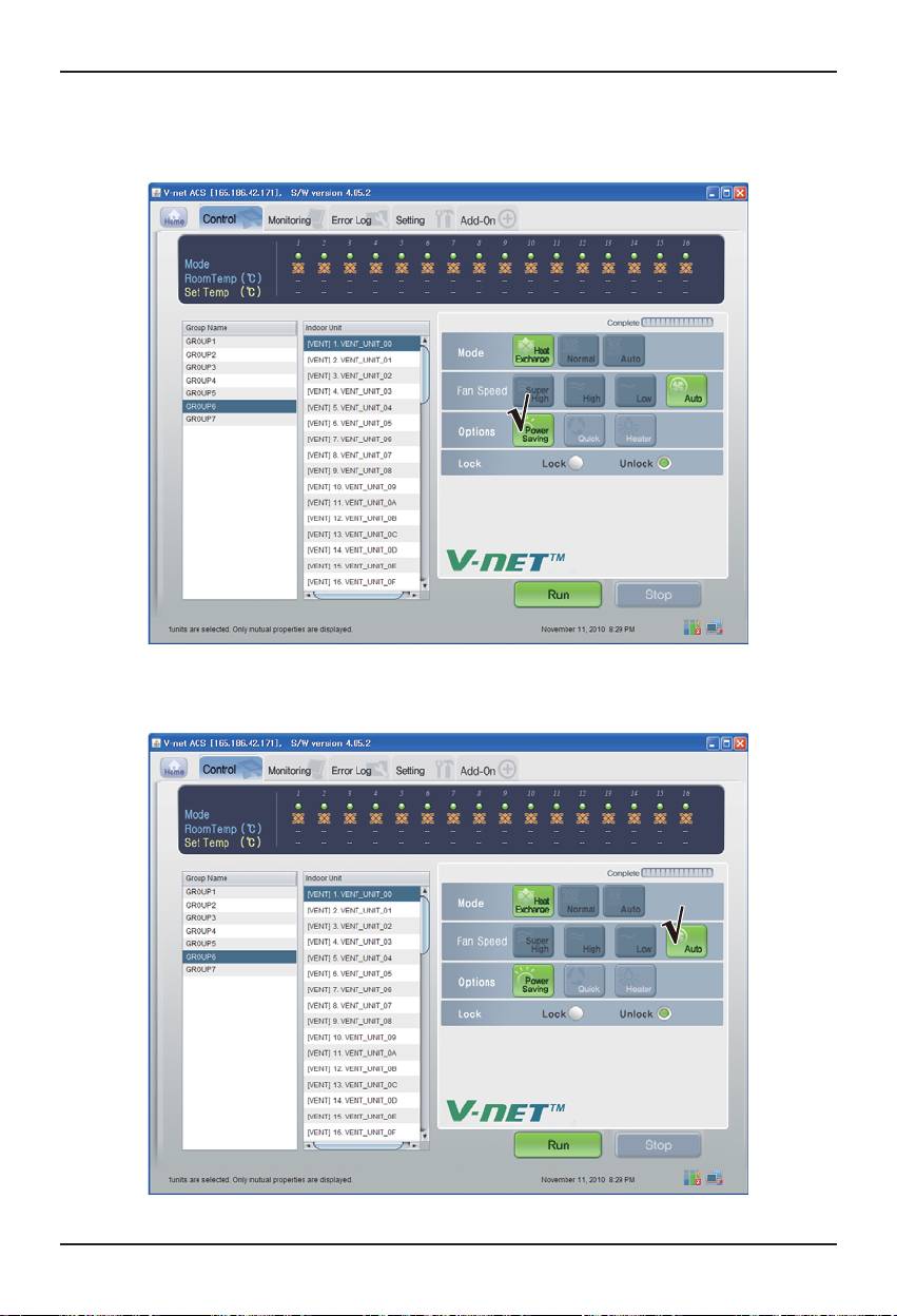
- Control : User Mode
(1) Click the Options(User Mode) button. (Power Saving/Quick/Heater)
< User Mode Control >
- Control : Fan Speed
(1) Click the Fan Speed button. (Super High/High/Low/Auto)
< Fan Speed Control >
44 BACnet Gateway
Test operation procedure
ENGLISH
■ AHU Control
Click the AHU Control Group
- Individual Control / Total Control
Click the unit which will be controlled for individual control or Click ALL for total control.
< Individual Control >
< Total Control >
Installation/Owner Manual 45
Test operation procedure
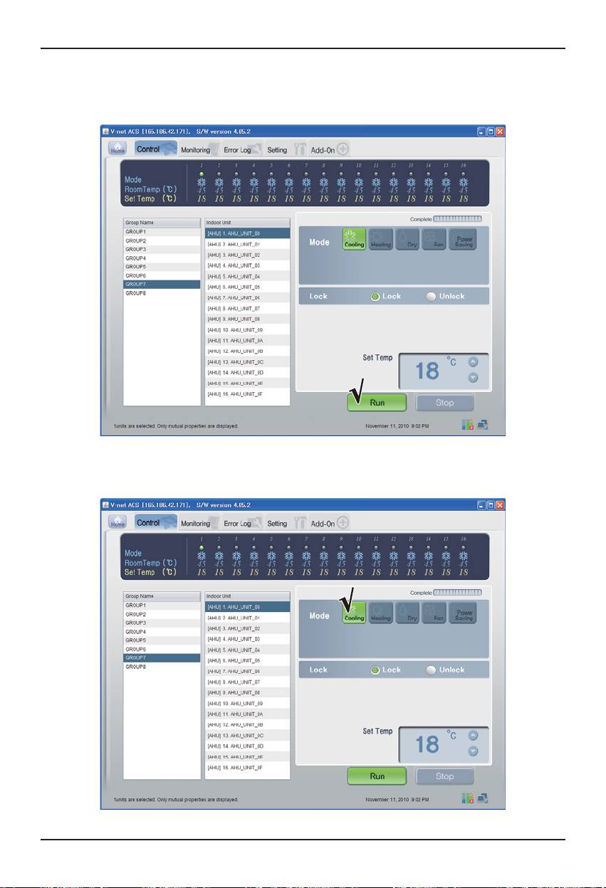
- Control : Run/Stop
(1) Click the Run/Stop button.
< Run/Stop Control >
- Control : Mode
(1) Click the Mode button. (Cooling/Heating/Dry/Fan/Power Saving)
< Mode Control>
46 BACnet Gateway
Test operation procedure
ENGLISH
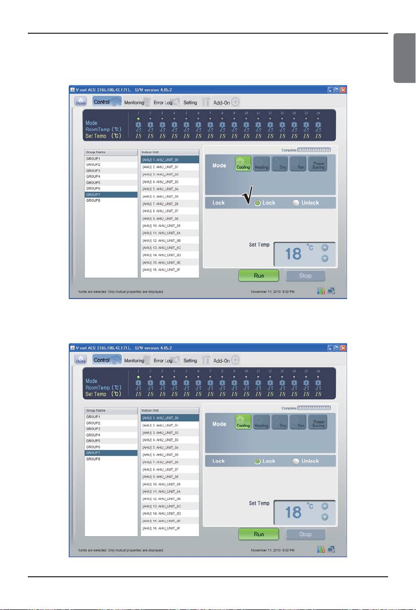
- Control : Lock/Unlock
(1) Click the Lock button. (Lock/Unlock)
< Lock/Unlock Control >
- Control:Temp.
(1) Click the Up/Down button for Set Temp.
< Temp. Control >
Installation/Owner Manual 47
Test operation procedure
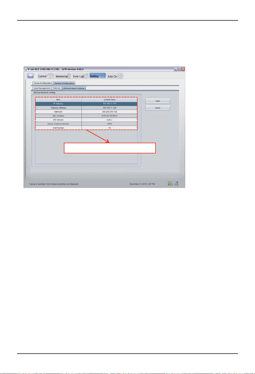
■ Confirming and adjusting the System Setting Information
(1) Click the ʻSettingʼ and General Configuration
(2) Confirm the BACnet Network Setting Information
Information of BACnet Gateway
48 BACnet Gateway
Functional Specifications BACnet Gateway
Functional Specifications BACnet Gateway
Summary
The BACnet G/W, in response to the requests from the BMS (Building management system which
supports BACnet-ANSI/ASHRAE135 protocol), status information of A/C/vent that are connected to
the BACnet G/W's internal LG-NET will be sent in BACnet service form, and BACnet client provides a
function that transmits control command to the A/C/vent system.
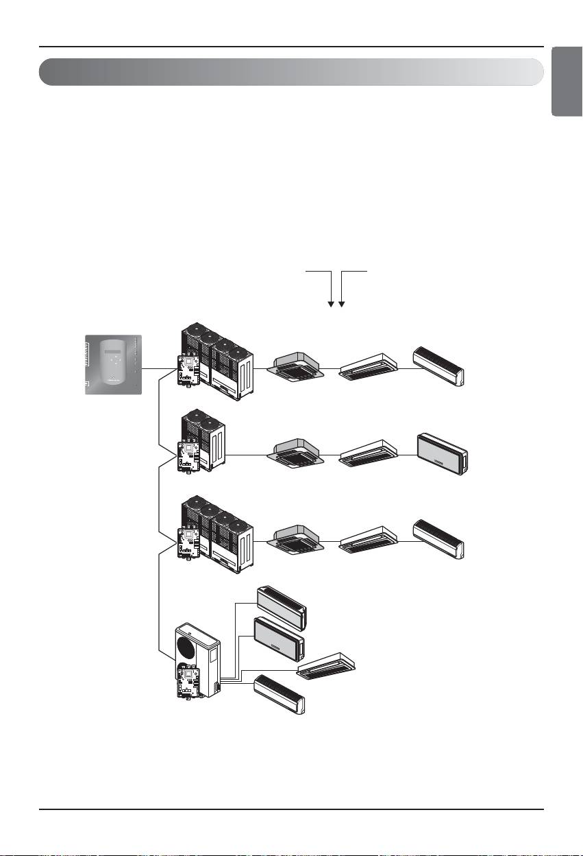
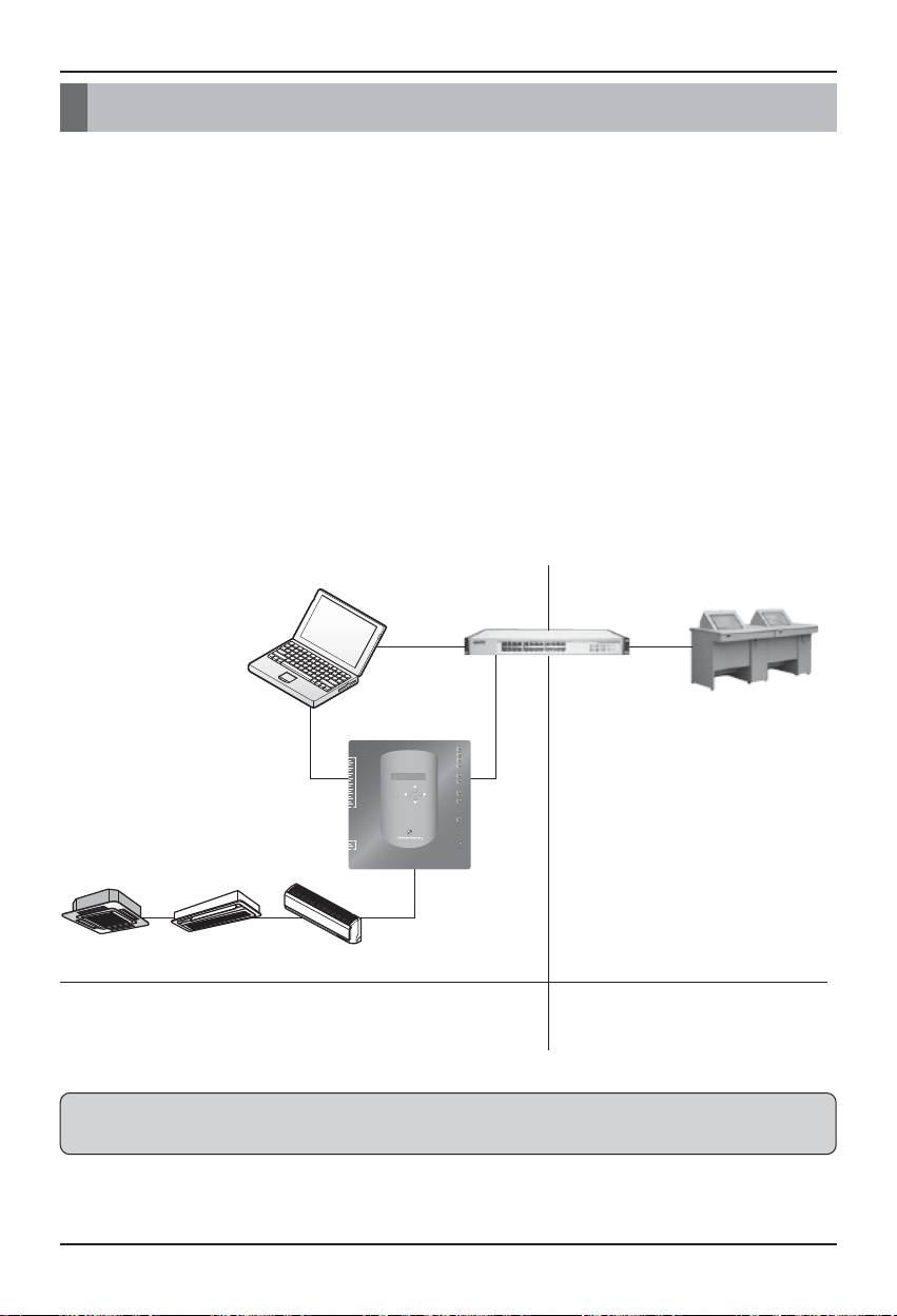
Configuration of Connection
A BACnet client that supports BACnet-ANSI/ASHRAE135 protocol allows direct connection via
generally used HUBs or Ethernet. The image of its connection configuration is as shown below.
BMS
Hub
Hub
LG-NET 1
TX
Outdoor unit
RX
TX
2
1
LG-NET 2
DI
RX
LG-NET 3
TX
L1 2 3 4
KSDO4H
4
3
RX
ON
LG-NET 4
TX
6
5
RX
8
7
Ext 1
TX
10
9
RX
12
11
Ext 2
TX
RX
14
13
16
15
Ethernet 1
ACT
LNK
18
17
SELECT
MENU/
Ethernet 2
ACT
19
LNK
20
Console
TX
RX
Centralized
2
1
Run
4
3
DO
Power
Remote controller
Indoor unit
Outdoor unit
ON
L1 2 3 4
KSDO4H
Centralized
Max.
Remote controller
Indoor unit
256
unit
Outdoor unit
ON
L1 2 3 4
KSDO4H
Centralized
Remote controller
Ventilation units
ENGLISH
Installation/Owner Manual 49

Functional Specifications BACnet Gateway
Monitoring and Controlling Items of A/C
The items to monitor and control A/C from BACnet communication as well as descriptions of each
item are listed below.
Function Description
Run/Stop (status) Monitors Run/Stop status of each A/C.
Operation Mode (status) Monitors cooling, heating, and vent operation status.
Lock (status) Indicates whether LOCK function of the A/C is active.
Set Temperature (status) Monitors the status of set temperature for A/C
Accumulator Power distribution (status)
Monitor the status of power distribution of A/C
Set Upper Temperature (status)
Monitors the status of upper temperature for A/C
Set Lower Temperature (status)
Monitors the status of lower temperature for A/C
Mode Lock (status) Indicates whether mode lock function of the A/C is active.
Fan speed (status) Monitors Fan speed of the functioning A/C.
Monitoring
Swing (status) Monitors swing mode of the indoor units.
Monitors the operation status of user mode (Quickoperation/Power
User Mode (status)
saving /Heater) while vent is functioning.
Monitors the room temperature and indicates the actual room
Room Temperature
temperature.
Filter Sign Monitors the status of the filters for vent
Monitors whether the A/C are operating properly and if not, alarm is set
Alarm
off.
Indicates the respective code for the errors occurred from the A/C
Error Code
system or the network.
Run/Stop (setting) Starts and stops the respective A/C and monitors control results.
Sets the operation mode (cooling, heating, vent or auto mode) and
Operation Mode (setting)
monitors the setting results.
Sets the additional operation mode in vent (quick fresh, energy
User Mode (setting)
efficiency, heating)
Swing (setting) Sets the air direction of the indoor unit.
Fan Speed (setting) Sets the airflow of the A/C
Lock (setting) Sets the lock of the A/Cʼs control authority.
Set Upper Temperature (setting)
Sets upper temperature of the respective A/C
Set Lower Temperature (setting)
Sets lower temperature of the respective A/C
Mode Lock (setting) Sets the mode lock of the A/Cʼs control authority.
Operation, Setting and Monitoring
Sets room temperature of the respective A/C and monitors the setting
Set Room Temperature
results.
Filter Sign Reset Resets the ventilationʼs filter limit indication.
50 BACnet Gateway

Functional Specifications BACnet Gateway
ENGLISH
Monitoring and Controlling point of indoor and ventilator
Applicable monitoring and controlling point for the indoor and ventilator are listed below.
Object Name's XX is indoor's address number.
Name Object Name Object Type Indoor Vent
1 Run/Stop (setting) StartStopCommand_XXX Binary Output O O
2 Run/Stop (status) StartStopStatus_XXX Binary Input O O
3 Lock (setting) LockCommand_XXX Binary Output O O
4 Lock (status) LockStatus_XXX Binary Input O O
5 Filter Sign FilterSign_XXX Binary Input X O
6 Filter Sign reset FilterSignReset_XXX Binary Value X O
7 Operation Mode (setting) ModeCommand_XXX Multistate Output O O
8 Operation Mode (status) ModeStatus_XXX Multistate Input O O
9 Swing (setting) SwingCommand_XXX Binary Output O X
10 Swing (status) SwingStatus_XXX Binary Input O X
11 Fan speed (setting) FanSpeedCommand_XXX Multistate Output O O
12 Fan speed (status) FanSpeedStatus_XXX Multistate Input O O
13 Set Room Temperature SetRoomTemp_XXX Analog Value O X
14 Room Temperature RoomTemp_XXX Analog Input O X
15 Alarm Alarm_XXX Binary Input O O
16 Error Code MalfunctionCode_XXX Analog Input O O
17 User Mode(setting) UserModeCommand_XXX Multistate Output X O
18 User Mode(status) UserModeStatus_XXX Multistate Input X O
19 Set Temperature (status) SetTempStatus_XXX Analog Input O X
Accumulator Power Distribution
20
AccumPowerStatus_XXX Analog Input O X
(status)
21 AC Operation Mode (setting) Hrv_ModeCommand_XXX Multistate Output X O
22 AC Operation Mode (status) Hrv_ModeStatus_XXX Multistate Input X O
HrvStartStopCommand_XX
23 AC ON/OFF (setting)
Binary Output X O
X
24 AC ON/OFF (status) HrvStartStopStatus_XXX Binary Input X O
25 Humidify (setting) HrvHumidifyCommand_XXX Binary Output X O
26 Humidify (status) HrvHumidifyStatus_XXX Binary Input X O
SetUpperTempCommand_X
27 Set Upper Temperature (setting)
Analog Value O X
XX
SetLowerTempCommand_X
28 Set Lower Temperature (setting)
Analog Value O X
XX
29 Set Upper Temperature (status) SetUpperTempStatus_XXX Analog Input O X
30 Set Lower Temperature (status) SetLowerTempStatus_XXX Analog Input O X
31 Mode Lock (setting) ModeLockCommand_XXX Binary Output O X
32 Mode Lock (status) ModeLockStatus_XXX Binary Input O X
Installation/Owner Manual 51

BACnet Protocol Implementation Conformance Statement (PICS)
BACnet Protocol Implementation Conformance Statement (PICS)
BACnet Protocol Implementation Conformance Statement
Date: 2007.06.01
Vendor name: LG Electronics Co. Ltd
Product name: BNU-BAC BACnet Gateway
Product Model Number:
Application Software version: 1.0 Firmware Revision:1.0 BACnet Revision: 1.0
Product Description:
This Gateway supports BACnet/IP and has a built-in Web-server that does not need any program-install.
It is able to interlock with the fire alarm through the separated Input/Output ports
BACnet Standardized Device Profile (Annex L):
❏ BACnet Operator Workstation (B-OWS)
❏ BACnet Building Controller (B-BC)
❏ BACnet Advanced Application Controller (B-AAC)
■ BACnet Application Specific Controller (B-ASC)
❏ BACnet Smart Senor (B-SS)
❏ BACnet Smart Actuator (B-SA)
Additional BACnet Interoperability Building Blocks Supported (Annex K)
Reference of BIBBs List(Appendix 1)
Segmentation Capability:
■ Segmented requests supported Window Size 16
■ Segmented responses supported Window Size 16
Standard Object Types Supported:
An object type is supported if it may be present in the device. For each standard Object Type
supported provide the following data:
1) Whether objects of this type are dynamically creatable
2) Whether objects of this type are dynamically deletable
52 BACnet Gateway

BACnet Protocol Implementation Conformance Statement (PICS)
ENGLISH
Data Link Layer Options:
BACnet IP, (Annex J)
■ BACnet IP, (Annex J), Foreign Device
❏ ISO 8802-3, Ethernet (Clause 7)
❏ ANSI/ATA 878.1, 2.5 Mb. ARCNET (Clause 8)
❏ ANSI/ATA 878.1, RS-485 ARCNET (Clause 8), baud rate(s)
❏ MS/TP master (Clause 9), baud rate(s):
❏ MS/TP slave (Clause 9), baud rate(s):
❏ Point-To-Point, EIA 232 (Clause 10), baud rate(s):
❏ Point-To-Point, modem, (Clause 10), baud rate(s):
❏ LonTalk, (Clause 11), medium:
❏ Other:
Device Address Binding:
Is static device binding supported? (This is currently necessary for two-way communication with
MS/TP slaves and certain other devices.) ❏ Yes ■ No
Networking Options:
❏ Router, Clause 6 - List all routing configurations, e.g., ARCNET-Ethernet, Ethernet-MS/TP, etc.
❏ Annex H, BACnet Tunneling Router over IP
❏ BACnet/IP Broadcast Management Device (BBMD)
Does the BBMD support registrations by Foreign Devices? ❏ Yes ■ No
Character Sets Supported:
Indicating support for multiple character sets does not imply that they can all be supported
simultaneously.
■ ANSI x 3.4 ❏ IBM™‚/Microsoft¢‚ DBCS ❏ ISO 8859-1
❏ ISO 10646 (UCS-2) ❏ ISO 10646 (UCS-4) ❏ JIS C 6226
If this product is a communication Gateway, describe the types of non-BACnet equipment/networks(s)
that the Gateway supports:
This Gateway converts BACnet protocol into LGAP(LG Aircon protocol), so that the outdoor unit of the
A/C which is connected to the Gateway is able to communicate in 485-communication.
Installation/Owner Manual 53

Objects (BACnet/IP)
Objects (BACnet/IP)
Supported Object Type
Monitoring and controlling items of air conditioners supported are assigned with general object types
specified by BACnet. Support status of each object type is shown in the table below.
(■ : Supported, ❏ : Unsupported)
Object Type Supported Description
Room Temperature, Error Code, Set Humidity,
Supply/Outer/Vent/Mixing Temperature,
Analog Input 0
Supply/Outer/Vent/Mixing Humidity, CO2 Value, Current
■
OA/EA/Mix Damper, Cool OA/EA/Mix Damper, Heat
OA/EA/Mix Damper, Fan OA/EA/Mix Damper
Set Humidity, Cool OA/EA/Mix Damper, Heat OA/EA/Mix
Analog Value 2
■
Damper, Fan OA/EA/Mix Damper
Run/Stop, Lock, Filter Sign, Swing, Alarm, Humidity,
Binary Input 3
Auto Ventilation, Humidifier, Heater, Ventilation Fan, Supply
■
Fan
Run/Stop, Lock, Mode Lock, Set Upper/Lower Temperature,
Binary Output 4
■
Swing, Humidity, Auto Ventilation
Binary-Value 5 Filter Sign Reset
■
Calendar 6
❏
Command 7
❏
Device 8
■
Event-Enrollment 9
❏
File 10
❏
Group 11
❏
Loop 12
❏
Operation Mode(Setting), Fan Speed(Setting)
Multistate-Output 13
■
User Mode(Setting)
Operation Mode(Status), Fan Speed(Status)
Multistate-Input 14
■
User Mode(Status)
Notification-Class 15
❏
Program 16
❏
Schedule 17
❏
Averagin 18
❏
Multistate-Value 19
❏
Trend-Log 20
❏
Life-Safety-Point 21
❏
Life-Safety-Zone 22
❏
54 BACnet Gateway

Objects (BACnet/IP)
ENGLISH
BACnet Point List : Indoor Unit
One indoor unit has the following 22 objects.
Text-5
Auto Heat
Auto
Auto
Text-4
High
Text-3
°C
Text-2
Middle
Start
Cool Dry Fan
Run
Run
Active
Prohibit
Prohibit
Abnormal
Unit
Stop
Text-0 Text-1
Permit
Inactive
-
-
BO Permit
BI
BI Stop
BI Normal
AI Reference LG Original Error Code
MO
BO
MO Low
MI Low Middle High
Type
Object
(XXX : Unit address)
ObjectName Product Name
StartStopCommand_XXX BO Stop
- -
-
ModeStatus_XXX MI Cool Dry Fan Auto Heat
SwingCommand_XXX
FanSpeedCommand_XXX
FanSpeedStatus_XXX
MalfunctionCode_XXX
-
- -
Name
ON/OFF (Setting)
ON/OFF (Status) StartStopStatus_XXX BI Stop Run
Lock (Setting) LockCommand_XXX
-
Mode (Status)
Swing (Setting)
Fan Speed (Setting)
Error Code
-
1
2
3
4 Lock (Status) LockStatus_XXX
5
6 -
7 Mode (Setting) ModeCommand_XXX
8
9
No.
10 Swing (Status) SwingStatus_XXX
11
12 Fan Speed (Status)
13 Set Room Temperature SetRoomTemp_XXX AV °C
14 Room Temperature RoomTemp_XXX AI
15 Alarm Alarm_XXX
16
17
18 -
Point
Installation/Owner Manual 55

Objects (BACnet/IP)
Text-5
Text-4
Text-3
Text-2
Text-1
Prohibit
Prohibit
°C
°C
°C
°C
Unit
Text-0
Permit
Inactive Active
AI
AV
AV
AI
BO
Type
Object
(XXX : Unit address)
ObjectName Product Name
SetTempStatus_XXX
SetUpperTempCommand_XXX
SetLowerTempCommand_XXX
SetLowerTempStatus_XXX
ModeLockCommand_XXX
Name
Set Temperature (status)
- - -
Set Upper Temperature (setting)
Mode Lock (setting)
No.
19
20
27
28 Set Lower Temperature (setting)
29 Set Upper Temperature (status) SetUpperTempStatus_XXX AI °C
30 Set Lower Temperature (status)
31
32 Mode Lock (status) ModeLockStatus_XXX BI Permit
Point
56 BACnet Gateway

Objects (BACnet/IP)
ENGLISH
BACnet Point List : Ventilation
One ventilation unit has the following 22 objects.
Auto
Auto
High
High
Super
Super
Normal
Heater
Heater
Auto Normal
Auto
Energy
Saving
Energy
Saving
Start
Heat
Heat
Exchange
Exchange
- Reset
Unit
Stop
Text-0 Text-1 Text-2 Text-3 Text-4 Text-5
Permit Prohibit
Permit Prohibit
Inactive Active
Normal Abnormal
-
-
-
-
BI Stop Run
BO
BI
BI Off On
MO
MI
MO Low High
MO Quick Fresh
MI Quick Fresh
Type
Object
(XXX : Unit address)
ObjectName Product Name
StartStopStatus_XXX
LockStatus_XXX
FilterSign_XXX
FilterSignReset_XXX BV
ModeStatus_XXX
-
FanSpeedCommand_XXX
FanSpeedStatus_XXX MI Low High
-
UserModeCommand_XXX
UserModeStatus_XXX
Name
Lock (Setting) LockCommand_XXX
Lock (Status)
Filter Sign Reset
Mode (Status)
-
Fan Speed (Setting)
- -
User Mode (Setting)
User Mode (Status)
1 ON/OFF (Setting) StartStopCommand_XXX BO
2 ON/OFF (Status)
3
4
5 Filter Sign
6
7 Mode (Setting) ModeCommand_XXX
8
9
No.
10 - -
11
12 Fan Speed (Status)
13 -
14
15 Alarm Alarm_XXX BI
16 Error Code MalfunctionCode_XXX AI Reference LG Original Error Code
17
18
Point
Installation/Owner Manual 57

Objects (BACnet/IP)
Text-4 Text-5
On
Cool Auto Heat
Run
Run
Text-1 Text-2 Text-3
Unit
Text-0
Inactive Active
AI °C
Type
Object
(XXX : Unit address)
ObjectName Product Name
SetTempStatus_XXX
HrvModeCommand_XXX MO
HrvStartStopStatus_XXX BI Stop
HrvHumidifyStatus_XXX BI Off
Name
- - -
AC Operation Mode (setting)
AC ON/OFF (status)
AC Humidify (status)
No.
19 Set Temperature (status)
20
21
22 AC Operation Mode (status) HrvModeStatus_XXX MI Cool Auto Heat
23 AC ON/OFF (setting) HrvStartStopCommand_XXX BO Stop
24
25 AC Humidify (setting) HrvHumidifyCommand_XXX BO Off On
26
Point
58 BACnet Gateway

Objects (BACnet/IP)
ENGLISH
BACnet Point List : AHU
One AHU unit has the following 53 objects.
Heat
Heat
Dry Fan
Dry Fan
Run
On
Cool
Active
Prohibit
Abnormal
Reference LG Original Error Code
Off
°C
°C
Unit
Stop Start
Stop
Stop Run
Text-0 Text-1 Text-2 Text-3 Text-4 Text-5
Inactive
-
-
-
BO
BI
BI Permit
MO
AV
BO
Type
Object
(XXX : Unit address)
ObjectName Product Name
StartStopCommand_XXX
StartStopStatus_XXX
LockStatus_XXX
FilterSign_XXX BI
FilterSignReset_XXX BV - Reset
ModeStatus_XXX MI Cool
-
-
-
FireAlarmCommand_XXX
Name
ON/OFF (Status)
Filter Sign
Filter Sign Reset
Mode (Setting) ModeCommand_XXX
- - -
Set Room Temperature SetRoomTemp_XXX
Error Code MalfunctionStatus_XXX AI
Set Temperature (Status) SetTempStatus_XXX AI
1 ON/OFF (Setting)
2
3 Lock (Setting) LockCommand_XXX BO Permit Prohibit
4 Lock (status)
5
6
7
8 Mode (Status)
9 - - -
No.
10
11 - - -
12 -
13
14 Room Temperature RoomTemp_XXX AI °C
15 Alarm Alarm_XXX BI Normal
16
17 -
18 -
19
20 Fire Alarm (Setting)
Point
Installation/Owner Manual 59

Objects (BACnet/IP)
Text-5
Text-2 Text-3 Text-4
Run
Run
Run
Run
Run
Text-1
Unit
Stop
Stop
Stop
Stop
0~90
0~90
Text-0
40~60
40_60
30~90
30~90
30~90
Inactive Active
-127~127
-127~127
0~255 (Real Value = Value*10, Example : In case Value is 20, CO2 is 20*10=200ppm)
AI
BO
AI
AI
AI
AI
BI
AI
Type
Object
(XXX : Unit address)
ObjectName Product Name
HumidifyStatus_XXX BI
SupplyTempStatus_XXX AI
HeaterUnitStatus_XXX BI
CurOADamperStatus_XXX AI
Name
Set Humidify (Status) SetHumidifyStatus_XXX
Humidify (Status)
Auto Ventilation (Setting) AutoVentCommand_XXX
Supply Temperature (Status)
Outdoor Temperature (Status) OutdoorTempStatus_XXX
Supply Humidity (Status) SupplyHumidifyStatus_XXX
Outdoor Humidity (Status) OutdoorHumidifyStatus_XXX
CO2 Value (Status) CO2ValveStatus_XXX
Heater Unit (Status)
Ventilation FAN (Status) VentFANStatus_XXX
Current OA Damper (Status)
Current EA Damper (Status) CurEADamperStatus_XXX
No.
21 Fire Alarm (Status) FireAlarmStatus_XXX BI Stop
22 Set Humidify (Setting) SethumidifyCommand_XXX AV
23
24 Humidify (Setting) HumidifyCommand_XXX BO Stop Run
25
26
27 Auto Ventilation (Status) AutoVentStatus_XXX BI Stop Run
28
29
30 Mix Temperature (Status) MixTempStatus_XXX AI -127~127
31
32
33 Ventilation Humidity (Status) VentHumidifyStatus_XXX AI
34
35 Humidify Unit (Status) HumidifyUnitStatus_XXX BI Stop Run
36
37
38 Supply FAN (Status) SupplyFANStatus_XXX BI Stop Run
39
40
Point
60 BACnet Gateway

Objects (BACnet/IP)
ENGLISH
Text-5
Text-3 Text-4
Text-2
Active
Unit
0~90
0~90
0~90
0~90
0~90
0~90
0~90
0~90
0~90
0~90
0~90
0~90
0~90
Text-0 Text-1
Inactive
AI 0~90
AV
AI
AV 0~90
AI
AV
AV 0~90
AI
AV
AI
Type
Object
(XXX : Unit address)
ObjectName Product Name
OADamperCoolCommand_XXX
EADamperCoolCommand_XXX AV
OADamperHeatCommand_XXX AV
OADamperHeatStatus_XXX AI 0~90
EADamperHeatStatus_XXX
MixDamperHeatStatus_XXX AI
OADamperFANCommand_XXX
MixDamperFANCommand_XXX
MixDamperFANStatus_XXX
Name
Cool OA Damper (Setting)
Cool MIX Damper (Status) MixDamperCoolStatus_XXX AI 0~90
Heat OA Damper (Setting)
Heat OA Damper (Status)
Heat EA Damper (Status)
Heat MIX Damper (Setting) MixDamperHeatCommand_XXX
Heat MIX Damper (Status)
Fan OA Damper (Setting)
Fan OA Damper (Status) OADamperFANStatus_XXX
Fan MIX Damper (Setting)
Fan MIX Damper (Status)
No.
41 Current MIX Damper (Status) CurMixDamperStatus_XXX
42
43 Cool OA Damper (Status) OADamperCoolStatus_XXX AI 0~90
44 Cool EA Damper (Setting)
45 Cool EA Damper (Status) EADamperCoolStatus_XXX
46 Cool MIX Damper (Setting) MixDamperCoolComman_XXX
47
48
49
50 Heat EA Damper (Setting) EADamperHeatCommand_XXX AV
51
52
53
54
55
56 Fan EA Damper (Setting) EADamperFANCommand_XXX AV
57 Fan EA Damper (Status) EADamperFANStatus_XXX AI
58
59
Point
Installation/Owner Manual 61

Objects (BACnet/IP)
Local Definition of Object ID - The instance number is a pair, this consists of the indoor unit No. and item.
31 22 21 0
Object ID
Object Type
Instance Number
21
17 16 15 12 11 8 7 0
Device No.
Product Unit No.
Point No.
Reserved(all 0)
(from 0 to 16)
(from 0 to 16)
(from 1 to 18)
Product Type(Indoor:0, Vent:1)
**Device : Group of Product units(16EA)
62 BACnet Gateway

Objects (BACnet/IP)
ENGLISH
Example of Point Table
The point table below is passed to BMS, and BMS registers the object.
• Case Indoor
Address Object Type Device No. Product No. Point Instance No. Name
0 4 0 0 1 0 x 00001(1) ON/OFF Setting
0 3 0 0 2 0 x 00002(2) ON/OFF Seatus
1 4 0 1 1 0 x 00101(257) ON/OFF Setting
1 3 0 1 2 0 x 00102(258) ON/OFF Seatus
15 4 0 15 1 0 x 00F01(3841) ON/OFF Setting
15 3 0 15 2 0 x 00F02(3842) ON/OFF Seatus
16 4 1 0 1 0 x 01001(4097) ON/OFF Setting
16 3 1 0 2 0 x 01002(4098) ON/OFF Seatus
17 4 1 1 1 0 x 01101(4353) ON/OFF Setting
17 3 1 1 2 0 x 01102(4354) ON/OFF Seatus
31 4 1 15 1 0 x 01F01(7937) ON/OFF Setting
31 3 1 15 2 0 x 01F02(7938) ON/OFF Seatus
32 4 2 0 1 0 x 02001(8193) ON/OFF Setting
32 3 2 0 2 0 x 02002(8194) ON/OFF Seatus
33 4 2 1 1 0 x 02101(8449) ON/OFF Setting
33 3 2 1 2 0 x 02102(8450) ON/OFF Seatus
47 4 2 15 1 0 x 02F01(12033) ON/OFF Setting
47 3 2 15 2 0 x 02F02(12034) ON/OFF Seatus
• Case Vent
Address Object Type Device No. Product No. Point Instance No. Name
0 4 0 0 1 0 x 10001(65537) ON/OFF Setting
0 3 0 0 2 0 x 10002(65538) ON/OFF Seatus
1 4 0 1 1 0 x 10101(65793) ON/OFF Setting
1 3 0 1 2 0 x 10102(65794) ON/OFF Seatus
15 4 0 15 1 0 x 10F01(69377) ON/OFF Setting
15 3 0 15 2 0 x 10F02(69378) ON/OFF Seatus
16 4 1 0 1 0 x 11001(69633) ON/OFF Setting
16 3 1 0 2 0 x 11002(69634) ON/OFF Seatus
17 4 1 1 1 0 x 11101(69889) ON/OFF Setting
17 3 1 1 2 0 x 11102(69890) ON/OFF Seatus
31 4 1 15 1 0 x 11F01(73473) ON/OFF Setting
31 3 1 15 2 0 x 11F02(73474) ON/OFF Seatus
32 4 2 0 1 0 x 12001(73729) ON/OFF Setting
32 3 2 0 2 0 x 12002(73730) ON/OFF Seatus
33 4 2 1 1 0 x 12101(73985) ON/OFF Setting
33 3 2 1 2 0 x 12201(73986) ON/OFF Seatus
47 4 2 F 1 0 x 12F01(77569) ON/OFF Setting
47 3 2 15 2 0 x 12F02(77570) ON/OFF Seatus
Installation/Owner Manual 63

Objects (Modbus-TCP)
Objects (Modbus-TCP)
Supported Function Code
Monitoring and controlling items of air conditioners supported are assigned with general function
codes specified by Modbus-TCP.
Function Name Code Description
Run/Stop(status), Lock(status), Swing(status), Alarm, Filter
Read Coil Status 01h
Sign(status), Mode Lock(status), Wind Flow Lock(status)
Operation Mode(status), Fan Speed(status),
Room Temperature, Error Code,
Set Room Temperature(status),
Read Holding Registers 03h
Set Lower Temperature(status),
Set Upper Temperature(status),
User Mode(status)
Run/Stop(setting), Lock(setting), Swing(setting),
Force Single Coil 05h
Filter Sign Reset, Mode Lock(setting),
Wind Flow Lock(setting)
Operation Mode(setting), Fan Speed(setting),
Set Room Temperature(setting),
Preset Single Registers 06h
Set Lower Temperature(setting),
Set Upper Temperature(setting),
User Mode(setting)
64 Modbus

Objects (Modbus-TCP)
ENGLISH
Modbus Point List : Indoor Unit
Function Code : 0x01 and 0x05
Inactive Active
Object Name
(XXX : Unit address)
ON/OFF StartStopStatus_XXX Stop Run
ON/OFF StartStopCommand_XXX Stop Run
Coil Read
Write Single Coil
Address Register Function Name
0x0000 1
0x0001 2 SWING SwingStatus_XXX Permit Prohibit
0x0002 3 LOCK LockStatus_XXX Permit Prohibit
0x0003 4 MODE LOCK ModeLockStatus_XXX Permit Prohibit
0x0004 5 FAN LOCK WindFlowLockStatus_XXX Permit Prohibit
0x0005 6 TEMP LOCK SetTempStatus-XXX Permit Prohibit
0x0006 7 ALARM Alarm_XXX Normal Abnormal
0x0000 1
0x0001 2 SWING SwingCommand_XXX Permit Prohibit
0x0002 3 LOCK LockCommand_XXX Permit Prohibit
0x0003 4 MODE LOCK ModeLockCommand_XXX Permit Prohibit
0x0004 5 FAN LOCK WindFlowLockCommand_XXX Permit Prohibit
0x0005 6 TEMP LOCK SetTempCommand-XXX Permit Prohibit
Installation/Owner Manual 65

Objects (Modbus-TCP)
Function Code : 0x03 and 0x06
Text-0 Text-1 Text-2 Text-3 Text-4 Text-5
Object Name
(XXX : Unit address)
SetTemp_XXX °C
SetTemp_XXX °C
OPERATION MODE ModeStatus_XXX Cool Dry Fan Auto Heat
SET ROOM TEMPERATURE
OPERATION MODE ModeStatus_XXX Cool Dry Fan Auto Heat
SET ROOM TEMPERATURE
Read Holding
Registers
Write Single
Registers
Address Register Function Name
0x0000 1
0x0001 2 FAN SPEED FanSpeedStatus_XXX Low Middle High Auto
0x0002 3
0x0003 4 UP_SETTEMP SetUpperTempStatus_XXX °C
0x0004 5 LO_SETTEMP SetLowerTempStatus_XXX °C
0x0005 6 ROOM TEMPERATURE RoomTemp_XXX °C
0x0006 7 ERROR CODE MalfunctionCode_XXX Reference LG original Error Code
0x0000 1
0x0001 2 FAN SPEED FanSpeedStatus_XXX Low Middle High Auto
0x0002 3
0x0003 4 UP_SETTEMP SetUpperTempStatus_XXX °C
0x0004 5 LO_SETTEMP SetLowerTempStatus_XXX °C
66 Modbus

Objects (Modbus-TCP)
ENGLISH
Modbus Point List : Ventilation
Function Code : 0x01 and 0x05
Inactive Active
Object Name
(XXX : Unit address)
ON/OFF StartStopStatus_XXX Stop Run
ON/OFF StartStopCommand_XXX Stop Run
Coil Read
Write Single Coil
Address Register Function Name
0x0000 1
0x0001 2 LOCK LockStatus_XXX Permit Prohibit
0x0002 3 FILTER SIGN FilterSign_XXX Off On
0x0003 4 ALARM HrvStartStopStatus_XXX Stop Run
0x0004 5 HRV_AC_OPER HrvStartStopStatus_XXX Stop Run
0x0005 6 HRV_HUMIDIFY HrvHumidifyStatus_XXX Off On
0x0000 1
0x0001 2 LOCK LockCommand_XXX Permit Prohibit
0x0002 3 FILTER SIGN RESET FilterSignReset_XXX Reset(Off) Void(On)
0x0004 5 HRV_AC_OPER HrvStartStopCommand_XXX Stop Run
0x0005 6 HRV_HUMIDIFY HrvHumidifyCommand_XXX Off On
Installation/Owner Manual 67

Objects (Modbus-TCP)
Function Code : 0x03 and 0x06
Auto
Auto
High
Heat
High
Heat
Super
Super
Auto Normal
Auto Normal
Energy
Saving
Energy
Saving
Heat
Quick
Heat
Low High
Quick
Exchange
Operation
Exchange
Operation
Text-0 Text-1 Text-2 Text-3 Text-4 Text-5
Object Name
(XXX : Unit address)
ModeStatus_XXX
ModeCommand_XXX
FanSpeedCommand_XXX
OPERATION MODE
OPERATION MODE
Read
Holding Registers
Write Single
Registers
Address Register Function Name
0x0000 1
0x0001 2 FAN SPEED FanSpeedStatus_XXX Low High
0x0002 3 USER MODE UserModeStatus_XXX
0x0003 4 ERROR CODE MalfunctionCode_XXX Reference LG original Error Code
0x0004 5 HRV_AC_MODE HrvModeStatus_XXX Cool Auto Heat
0x0005 6 HRV_SETTEMP HrvSetTempstatus_XXX °C
0x0000 1
0x0001 2 FAN SPEED
0x0002 3 USER MODE UserModeStatus_XXX
0x0004 5 HRV_AC_MODE HrvModeStatus_XXX Cool Auto Heat
0x0005 6 HRV_SETTEMP HrvSetTempstatus_XXX °C
68 Modbus

Objects (Modbus-TCP)
ENGLISH
Modbus Point List : AHU
Function Code : 0x01 and 0x05
Inactive Active
Object Name
(XXX : Unit address)
ON/OFF StartStopStatus_XXX Stop Run
ON/OFF StartStopCommand_XXX Stop Run
Coil Read
Write Single Coil
Address Register Function Name
0x0000 1
0x0001 2 LOCK LockStatus_XXX Permit Prohibit
0x0002 3 FILTER SIGN FilterSign_XXX Off On
0x0003 4 SMOKE FireAlarmStatus_XXX Stop Run
0x0004 5 HUMIDITY HumidifyStatus_XXX Stop Run
0x0005 6 AUTO VENT AutoVentStatus_XXX Stop Run
0x0006 7 HUMIDIFIER HumidifiyUnitStatus-XXX Stop Run
0x0007 8 HEATER HeaterUnitStatus_XXX Stop Run
0x0008 9 VENT FAN VentFANStatus_XXX Stop Run
0x0009 10 SUPPLY FAN SupplyFANStatus_XXX Stop Run
0x000A 11 ALARM Alarm_XXX Normal Abnormal
0x0000 1
0x0001 2 LOCK LockCommand_XXX Permit Prohibit
0x0003 4 SMOKE FireAlarmCommand_XXX Stop Run
0x0004 5 HUMIDITY HumidifyCommand_XXX Stop Run
0x0005 6 AUTO VENT AutoVentCommand_XXX Stop Run
Installation/Owner Manual 69

Objects (Modbus-TCP)
Function Code : 0x03
Text-4 Text-5
POWSAV Heat
Text-3
Text-0 Text-1 Text-2
Object Name
(XXX : Unit address)
MODE ModeStatus_XXX Cool Dry Fan
Read
Holding
Registers
Address Register Function Name
0x0000 1
0x0001 2 SET TEMP SetTempStatus_XXX °C
0x0002 3 SUPPLY TEMP SupplyTempStatus_XXX -127~127
0x0003 4 OUTDOOR TEMP OutdoorTempStatus_XXX -127~127
0x0004 5 VENT TEMP VentTempStatus_XXX -127~127
0x0005 6 MIXING TEMP MixingTempStatus_XXX -127~127
0x0006 7 SET HUMIDITY SetHumidityStatus_XXX 40~60
0x0007 8 SUPPLY HUMIDITY SupplyHumidityStatus_XXX 30~90
0x0008 9 OUTDOOR HUMIDITY OutdootHumidityStatus_XXX 30~90
0x0009 10 VENT HUMIDITY VentHumidityStatus_XXX 30~90
0x000A 11 CO2 VALUE CO2ValueStatus_XXX 0 ~ 255
0x000B 12 ERROR CODE MalfunctionCode_XXX Reference LG original Error Code
0x0010 17 CURR_OA_DAMPER CurOADamperStatus_XXX 0~90
0x0011 18 CURR_EA_DAMPER CurEADamperStatus_XXX 0~90
0x0012 19 CURR_MIX_DAMPER CurMixDamperStatus_XXX 0~90
0x0013 20 COOL_OA_DAMPER OADamperCoolStatus_XXX 0~90
0x0014 21 COOL_EA_DAMPER EADamperCoolStatus_XXX 0~90
0x0015 22 COOL_MIX_DAMPER MixDamperCoolStatus_XXX 0~90
0x0016 23 HEAT_OA_DAMPER OADamperHeatStatus_XXX 0~90
0x0017 24 HEAT_EA_DAMPER EADamperHeatStatus_XXX 0~90
0x0018 25 HEAT_MIX_DAMPER MixDamperHeatStatus_XXX 0~90
0x0019 26 FAN_OA_DAMPER OADamperFANStatus_XXX 0~90
0x001A 27 FAN_EA_DAMPER EADamperFANStatus_XXX 0~90
0x001B 28 FAN_MIX_DAMPER MixDamperFANStatus_XXX 0~90
70 Modbus

Objects (Modbus-TCP)
ENGLISH
Function Code : 0x06
Heat
POWSAV
Text-0 Text-1 Text-2 Text-3 Text-4 Text-5
Object Name
(XXX : Unit address)
MODE ModeCommand_XXX Cool Dry Fan
Write Single
Registers
Address Register Function Name
0x0000 1
0x0001 2 SET TEMP SetTempCommand_XXX °C
0x0006 7 SET HUMIDITY SetHumidityCommand_XXX 40~60
0x0013 20 COOL_OA_DAMPER CoolOADamperCommand_XXX 0~90
0x0014 21 COOL_EA_DAMPER CoolEADamperCommand_XXX 0~90
0x0015 22 COOL_MIX_DAMPER CoolMixDamperCommand_XXX 0~90
0x0016 23 HEAT_OA_DAMPER HeatOADamperCommand_XXX 0~90
0x0017 24 HEAT_EA_DAMPER HeatEADamperCommand_XXX 0~90
0x0018 25 HEAT_MIX_DAMPER HeatMixDamperCommand_XXX 0~90
0x0019 26 FAN_OA_DAMPER FANOADamperCommand_XXX 0~90
0x001A 27 FAN_EA_DAMPER FANEADamperCommand_XXX 0~90
0x001B 28 FAN_MIX_DAMPER FANMixDamperCommand_XXX 0~90
Installation/Owner Manual 71

Objects (Modbus-TCP)
Local Definition of Object ID - The instance number is a pair, this consists of the indoor unit No. and item.
19 16 15 0
Address
Object Type Instance Number
034111215 78
Device No.
Product Unit No.
Point No.
Product Type
(from 0 to 16)
(from 0 to 16)
(from 0 to 16)
* Object Type (Coil : 0, Register : 4)
* Product Type (Indoor : 0, Vent 4)
** Device : Group of Product units (16EA)
72 Modbus

Objects (Modbus-TCP)
ENGLISH
Example of Point Table
The point table below is passed to BMS, and BMS registers the object.
• Case Indoor
Function Code Device No. Product No. Point Instance No. Name
1 0 0 0 0x00000 ON/OFF status
5 0 0 0 0x00000 ON/OFF setting
1 0 1 0 0x00010 ON/OFF status
5 0 1 0 0x00010 ON/OFF setting
1 1 0 0 0x00100 ON/OFF status
5 1 0 0 0x00100 ON/OFF setting
3 0 0 0 0x40000 Mode status
6 0 0 0 0x40000 Mode setting
3 0 1 0 0x40010 Mode status
6 0 1 0 0x40010 Mode setting
3 1 0 0 0x40100 Mode status
6 1 0 0 0x40100 Mode setting
• Case Vent
Function Code Device No. Product No. Point Instance No. Name
1 0 0 0 0x04000 ON/OFF status
5 0 0 0 0x04000 ON/OFF setting
1 0 1 0 0x04010 ON/OFF status
5 0 1 0 0x04010 ON/OFF setting
1 1 0 0 0x04100 ON/OFF status
5 1 0 0 0x04100 ON/OFF setting
3 0 0 0 0x44000 Mode status
6 0 0 0 0x44000 Mode setting
3 0 1 0 0x44010 Mode status
6 0 1 0 0x44010 Mode setting
3 1 0 0 0x44100 Mode status
6 1 0 0 0x44100 Mode setting
Installation/Owner Manual 73

Objects (Modbus-TCP)
• Case AHU
Function Code Device No. Product No. Point Instance No. Name
1 0 0 0 0x08000 ON/OFF status
5 0 0 0 0x08000 ON/OFF setting
1 0 1 0 0x08010 ON/OFF status
5 0 1 0 0x08010 ON/OFF setting
1 1 0 0 0x08100 ON/OFF status
5 1 0 0 0x08100 ON/OFF setting
3 0 0 0 0x48000 Mode status
6 0 0 0 0x48000 Mode setting
3 0 1 0 0x48010 Mode status
6 0 1 0 0x48010 Mode setting
3 1 0 0 0x48100 Mode status
6 1 0 0 0x48100 Mode setting
74 Modbus

Detailed Explanation of Object
ENGLISH
Detailed Explanation of Object
1) Common to All Objects
Objects related to the air conditioner in communication are treated on the BACnet as described
below.
- Air Conditioner in Normal Communication
Other BACnet devices can access each object related to the air conditioner.
- Air Conditioner Unconnected
It seems to other BACnet devices that no objects related to the air conditioner exist.
Therefore, when the ReadProperty/WriteProperty service is received, the following ErrorPDU will
be returned.
Error class: OBJECT; Error type: UNKNOWN_PROPERTY
- Air Conditioner Communication Error
Other BACnet device can access the objects related to the air conditioners, but the
Present_Value Property will be read in a value immediately before the communication error.
2) Run/Stop (Setting)
Point number: 1
Object name: StartStopCommand_XXX (XXX: A/C unit address)
Object type: Binary Output
Meaning: This object is used to give Run/Stop commands to the air conditioner.
Present_Value property:
ACTIVE: Run command
INACTIVE: Stop command
Remarks: 1. The command executed is transmitted to the A/C regardless of the status of the A/C.
2. Present_Value property will not be used if a property has never been set in the past.
3) Run/Stop (Status)
Point number: 2
Object name: StartStopStatus_XXX (XXX: A/C unit address)
Object type: Binary Input
Meaning: This object is used to monitor the Run/Stop status of the air conditioner.
Present_Value property:
ACTIVE: Run
INACTIVE: Stop
Remarks: If there is an operation error, the Present_Value property will be set to ACTIVE
regardless of whether the A/C is in operation or not.
Installation/Owner Manual 75

Detailed Explanation of Object
4) Lock (setting)
Point number: 3
Object name: LockCommand_XXX (XXX: A/C unit address)
Object type: Binary Output
Meaning: This object is used to set the Lock of the A/C's control authority.
Present_Value property:
ACTIVE: Lock (Restricted)
INACTIVE: Unlock (Not restricted)
5) Lock (status)
Point number: 4
Object name: LockStatus_XXX (XXX: A/C unit address)
Object type: Binary Input
Meaning: This object is used to monitor the Lock of the A/C's control authority.
Present_Value property:
ACTIVE: Lock (Restricted)
INACTIVE: Unlock (Not restricted)
6) Filter Sign
Point number: 5
Object name: FilterSign_XXX (XXX: A/C unit address)
Object type: Binary Input
Meaning: This object is used to monitor the status of the filters for vent.
Present_Value property:
ACTIVE: Filter sign information is turned ON.
INACTIVE: Filter sign information is OFF.
Remarks: This object supports the Intrinsic Reporting function. When the Present_Value property
changes, the corresponding Event will be transmitted if the Event has been registered.
7) Filter Sign Reset
Point number: 6
Object name: FilterSignReset_XXX (XXX: A/C unit address)
Object type: Binary Value
Meaning: This object is used to reset the vent°Øs limit indication.
Present_Value property:
INACTIVE: Filter indication information is reset.
Remarks: 1. During a read operation of the Present_Value property, the Fliter Limit Sign Reset will
be always the same value as the Filter Limit Sign object.
2. Only if INACTIVE is written to the Present_Value property during a write operation,
the filter sign information resets ON signs and nothing will be executed even if
ACTIVE is written.
3. This object supports the Intrinsic Reporting function. When the Present_Value
property changes, the corresponding Event will be transmitted if the Event has been
registered.
76 BACnet Gateway

Detailed Explanation of Object
ENGLISH
8) Operation Mode (Setting)
Point number: 7
Object name: ModeCommand_XXX (XXX: A/C unit address)
Object type: Multistate Output
Meaning: This object is used to set the operation modes of the air conditioner.
Present_Value property:
Indoor Vent
1: Cool HEX
2: Dry Auto
3: Fan Normal
4: Auto -
5: Heat -
Remarks: 1. The Present_Value property will be set to "1: Cool" as the default value if property
has never been set in the past.
2. The air conditioner will ignore the command to an object that does not have right to
select operation mode. Therefore, the controlled/monitored system must not use this
object for the air conditioner without the right to select operation mode.
9) Operation Mode (Status)
Point number: 8
Object name: ModeStatus_XXX (XXX: A/C unit address)
Object type: Multistate Input
Meaning: This object is used to monitor the operation modes of the air conditioner.
Present_Value property:
Indoor Vent
1: Cool HEX
2: Dry Auto
3: Fan Normal
4: Auto -
5: Heat -
10) Swing (Setting)
Point number: 9
Object name: SwingCommand_XXX (XXX: A/C unit address)
Object type: Binary Output
Meaning: This object is to set the air direction of the indoor unit.
Present_Value property:
ACTIVE: Run
INACTIVE: Stop
Installation/Owner Manual 77

Detailed Explanation of Object
11) Swing (Status)
Point number: 10
Object name: SwingStatus_XXX (XXX: A/C unit address)
Object type: Binary Input
Meaning: This object is to monitor the air direction of the A/C.
Present_Value property:
ACTIVE: Swing_On
INACTIVE: Swing_Off
12) Fan Speed (Setting)
Point number: 11
Object name: FanSpeedCommand_XXX (XXX: A/C unit address)
Object type: Multistate Output
Meaning: This object is to set the airflow of the A/C.
Present_Value property:
Indoor Vent
1: Low Low
2: Middle High
3: High Super High
4: Auto Auto
Remarks:
The A/C will disregard the command which the object which can't select the operation mode.
Therefore, controlled/monitored system shouldn't use the object which can't select the
operation mode.
13) Fan Speed (Status)
Point number: 12
Object name: FanSpeedStatus_XXX (XXX: A/C unit addresss)
Object type: Multistate Input
Meaning: This object is to monitor the airflow of the A/C.
Present_Value property:
Indoor Vent
1: Low Low
2: Middle High
3: High Super High
4: Auto Auto
Remarks: Present_value property will be set to "1:Low" as the default result if the property has
not been set in the past.
78 BACnet Gateway

Detailed Explanation of Object
ENGLISH
14) Set Room Temperature
Point number: 13
Object name: SetRoomTemp_XXX (XXX: A/C unit address)
Object type: Analog Value
Meaning: This object is used to set the room temperature for the air conditioner.
Present_Value property:
Temperature(°C)
Remarks:
1. This unit is for indoor units only, and the approximate set temperature range is 18 ~ 35°C.
2. When COV registration is made, the COV will be reported the moment a temperature change
of at least
1°C is detected.
15) Room Temperature
Point number: 14
Object name: RoomTemp_XXX (XXX: A/C unit address)
Object type: Analog Input
Meaning: This object is used to monitor room temperature which the indoor unit is placed.
Present_Value property:
Temperature(°C)
Remarks: This object is for indoor units only, and reports the room temperature data measured
by the indoor units.
16) Alarm
Point number: 15
Object name: Alarm_XXX (XXX: A/C unit address)
Object type: Binary Input
Meaning: This object is used to monitor the Alarm.
Present_Value property:
ACTIVE: Alarm_On
INACTIVE: Alarm_Off
17) Error Code
Point number: 16
Object name: MalfunctionCode_XXX (XXX: A/C unit address)
Object type: Analog Input
Meaning: This object is used to monitor the details of the error status when the air conditioner
has an error.
Present_Value property:
Error code(Range is 0 to 255 )
Remarks: This object's error code descriptions should be referred to the corresponding table at
the "Reference LG original Error Code".
Installation/Owner Manual 79

Detailed Explanation of Object
18) User Mode (Setting)
Point number: 17
Object name: UserModeCommand_XXX (XXX: A/C unit address)
Object type: Multi-state Output
Meaning: This object is used to set the basic operation mode in vent and also additional
operation mode (quick fresh, energy efficiency, and heating).
Present_Value property:
1: Quick
2: Saving
3: Heater
Remarks:
This object is for vent only, and will not apply if the property has not been set in the past.
19) User Mode (Status)
Point number: 18
Object name: UserModeStatus_XXX (XXX: A/C unit address)
Object type: Multi-state Input
Meaning : This object is used to monitor the basic operation mode in vent
Property_Value property:
1: Quick
2: Saving
3: Heater
Reamark : This object is for vent only, and will not apply if the property has not been in the past.
20) Set Temperature (status)
Point number: 19
Object name: SetTempStatus_XXX (XXX: A/C unit address)
Object type: Analog Output
Meaning: This object is used to monitor the set temperature of the A/C's control authority.
Present_Value property:
Temperature(°C)
Remarks : This object is for indoor units only, and reports the room temperature data measured
by the indoor units.
21) Accumulator Power Distribution (status)
Point number: 20
Object name: AccumPowerStatus_XXX (XXX: A/C unit address)
Object type: Analog Input
Meaning: This object is used to monitor the accumulator power distribution of the A/C's control
authority.
Present_Value property:
Range is 0 to 255 (Power Distributiion : count * 100Watt)
80 BACnet Gateway

Detailed Explanation of Object
ENGLISH
22) AC Operation Mode (setting)
Point number: 21
Object name: HrvModeCommand_XXX (XXX: DXHRV unit address)
Object type: Multistate Output
Meaning: This object is used to set the A/C operation mode of the DXHRV.
Present_Value property:
1 : Cool
2 : Auto
3 : Heat
23) AC Operation Mode (status)
Point number: 22
Object name: HrvModeStatus_XXX (XXX: DXHRV unit address)
Object type: Multistate Input
Meaning: This object is used to monitor the A/C operation mode of the DXHRV.
Present_Value property:
1 : Cool
2 : Auto
3 : Heat
24) AC Run/Stop (setting)
Point number: 23
Object name: HrvStartStopCommand_XXX (XXX: DXHRV unit address)
Object type: Binary Output
Meaning: This object is used to set the A/C Run/Stop status of the DXHRV.
Present_Value property:
ACTIVE: Run command
INACTIVE: Stop command
25) AC Run/Stop (setting)
Point number: 24
Object name: HrvStartStopStatus_XXX (XXX: DXHRV unit address)
Object type: Binary Input
Meaning: This object is used to monitor the A/C Run/Stop status of the DXHRV.
Present_Value property:
ACTIVE: Run
INACTIVE: Stop
Installation/Owner Manual 81

Detailed Explanation of Object
26) AC Humidify (setting)
Point number: 25
Object name: HrvHumidifyCommand_XXX (XXX: DXHRV unit address)
Object type: Binary Output
Meaning: This object is used to set the A/C humidify status of the DXHRV.
Present_Value property:
ACTIVE: ON command
INACTIVE: OFF command
27) AC Humidify (status)
Point number: 26
Object name: HrvStartStopStatus_XXX (XXX: DXHRV unit address)
Object type: Binary Input
Meaning: This object is used to monitor the A/C humidify status of the DXHRV.
Present_Value property:
ACTIVE: ON
INACTIVE: OFF
28) Set Upper Temperature (setting)
Point number: 27
Object name: SetUpperTempCommand_XXX (XXX: A/C unit address)
Object type: Analog Value
Meaning: This object is used to set the upper temperature for the air conditioner.
Present_Value property:
Temperature(°C)
Remarks:
1.
This unit is for indoor units only, and the approximate set upper temperature range is 18 ~ 30°C.
1°C is detected.
29) Set Upper Temperature (status)
Point number: 28
Object name: SetUpperTempStatus_XXX (XXX: A/C unit address)
Object type: Analog Input
Meaning: This object is used to monitor set upper temperature which the indoor unit is placed.
Present_Value property:
Temperature(°C)
Remarks: This object is for indoor units only, and reports the set upper temperature data
measured by the indoor units.
82 BACnet Gateway

Detailed Explanation of Object
ENGLISH
30) Set Lower Temperature (setting)
Point number: 29
Object name: SetLowerTempCommand_XXX (XXX: A/C unit address)
Object type: Analog Value
Meaning: This object is used to set the lower temperature for the air conditioner.
Present_Value property:
Temperature(°C)
Remarks:
1.
This unit is for indoor units only, and the approximate set lower temperature range is 18 ~ 30°C.
1°C is detected.
31) Set Lower Temperature (status)
Point number: 30
Object name: SetLowerTempStatus_XXX (XXX: A/C unit address)
Object type: Analog Input
Meaning: This object is used to monitor set lower temperature which the indoor unit is placed.
Present_Value property:
Temperature(°C)
Remarks: This object is for indoor units only, and reports the set lower temperature data
measured by the indoor units.
32) Mode Lock (setting)
Point number: 31
Object name: ModeLockCommand_XXX (XXX: A/C unit address)
Object type: Binary Output
Meaning: This object is used to set the mode lock of the A/C's control authority.
Present_Value property:
ACTIVE: Lock (Restricted)
INACTIVE: Unlock (Not restricted)
33) Mode Lock (status)
Point number: 32
Object name: ModeLockStatus_XXX (XXX: A/C unit address)
Object type: Binary Input
Meaning: This object is used to monitor the mode lock of the A/C's control authority.
Present_Value property:
ACTIVE: Lock (Restricted)
INACTIVE: Unlock (Not restricted)
Installation/Owner Manual 83

Initialization at the Start Up
Initialization at the Start Up
The system is designed to automatically recognize the connected air conditioners. Therefore, a period
of approximately one minute will be required to recognize all the air conditioners after the system is
turn on. During this period, the following error PDU may be returned when an object corresponding to
an air conditioner is accessed.
ErrorClass = Object; ErrorCode = Unknown_Object
If an attempt is made to read the Object List property of the Device object from an air conditioner
during the above period of recognition, the following error PDU will be returned, unless the air
conditioner has been recognize:
ErrorClass = Device; ErrorCode = Configuration_In_Progress
Detail Error response refer to Appendix 3.
Clock Setting
The Timesynchronization service allows clock settings by the local time.
Furthermore, the UTCTimesycchronization allows clock settings by UTC
Report Function
Event Notification
1) Registration of Event Notification Destination
It is possible to use the AddListElement service to register notification destination information on
the Recipient List property of the Notification Class object.
2) Deletion of Event Notification Destination
The RemoveListElement service can be used to delete notification destination information from the
Notification
Class object.
3) Event Notification Destination in Memory
The registered event notification destination is stored in the memory. When the system is turned
on, the event notification destination will be initialized with the stored information. The Event
notification destination will
be stored five seconds after the registration or deletion.
84 BACnet Gateway

Report Function
ENGLISH
COV(Change of Value) Notification
A request for COV registration is accepted through the SubscribeCOV service.
1) Setting of Confirmed or Unconfirmed COV
This item is supported according to the BACnet Specifications.
2) Setting of the desired lifetime of the subscription
This item is supported according to the BACnet Specifications.
When COV notification is made at the time of status change, the difference between the registered
time and present time will be calculated. If the difference is greater than the registered lifetime of
the subscription, the subscription will be judged expired and deleted. Therefore, if a clock time
change is made, the lifetime of the subscription may differ from the value that has been set.
3) Memory after Interruption of Power Supply to System
This item is not supported. Registration information is not stored in the memory, and will be lost
when the power is turned off. According to the BACnet Specifications, It is not required to
guarantee preservation of subscriptions across power failure.
Supported COV service is shown in the follow table
Service Object Product
On/Off (status) Binary Input object property Indoor, vent
Lock On/Off (status) Binary Input object property Indoor, vent
Mode Lock (status) Binary Input object property Indoor
Wind Flow Lock (status) Binary Input object property Indoor
Set Upper Temperature (status) Analog Input object property Indoor
Set Lower Temperature (status) Analog Input object property Indoor
Operation mode (status) Multistate input object property Indoor, vent
Swing (status) Binary Input object property Indoor
Filter Sign Binary Input object property Vent
Fan Speed (status) Multistate Input object property Indoor, vent
Set Room Temperature Analog value object property Indoor
Room Temperature Analog input object property Indoor
Alarm Binary Input object property Indoor, vent
Error Code Analog Input object property Indoor, vent
User mode Multistate input object property vent
Installation/Owner Manual 85
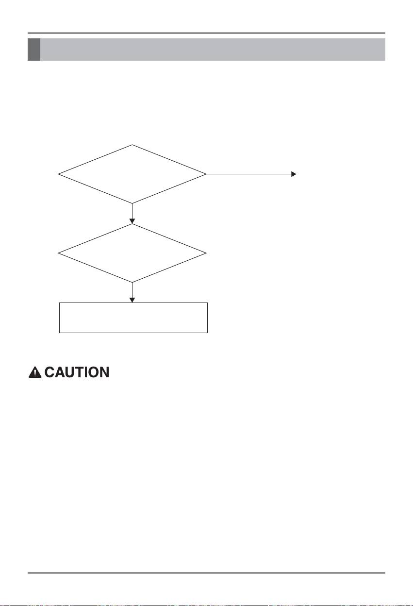
Troubleshooting
Troubleshooting
- Problem : The Power LED of the BACnet Gateway is not lit.
→ If the power is normally applied, the Power LED is lit.
- Expected cause : The power is not applied
The specified adaptor is not used
- Diagnosis
NO
Is the power is applied? Apply the power
YES
Is the specified adaptor used?
NO
Apply the power via
the specified adaptor
The power switch should be turned off when connecting/disconnecting the BACnet
Gateway to/from the other device. Otherwise, it may cause to damage the part of the
Gateway.
86 BACnet Gateway
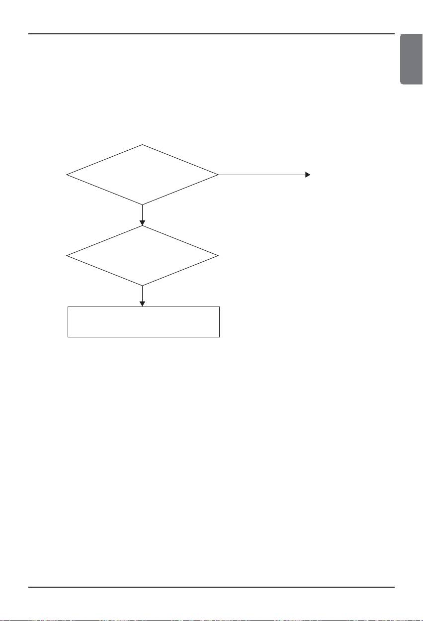
Troubleshooting
- Problem : The RUN LED of the BACnet Gateway is not blinked.
→ If the Gateway normally operates, the RUN LED periodically blinks.
- Expected cause : The power is not applied
The program is not correctly installed
- Diagnosis
Is the power is
NO
Apply the power.
applied?
YES
Is the program correctly
installed?
NO
Reinstall the program
ENGLISH
Installation/Owner Manual 87
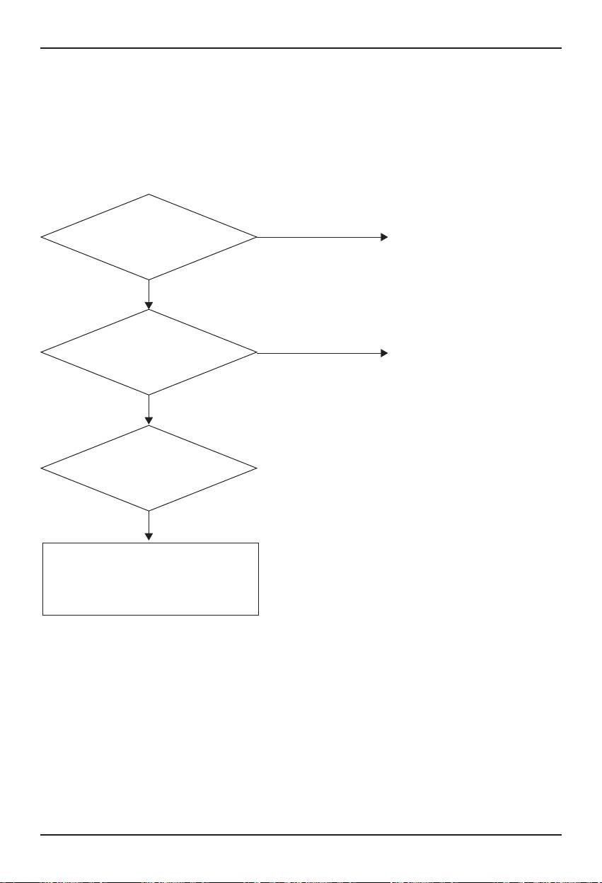
Troubleshooting
- Problem : The LNK/ACT LED of the Ethernet 1.2 of the BACnet Gateway is not lit/blinked.
→ The LNK LED is lit when the LAN communication of the Gateway correctly operates.
- Expected cause : The power is not applied to the hub
The Gateway is disconnected from the hub
The Gateway is not connected to the hub with direct cable
- Diagnosis
NO
Is the power is applied
Apply the power to the hub.
to the hub?
YES
NO
Is the Gateway connected
Connect the gateway to the hub.
to the hub?
YES
Is the Gateway connected to
the hub with the direct cable?
NO
If it is connected with the cross cable,
replace it with the direct cable.
(For more information about the cable,
see the following page.)
88 BACnet Gateway
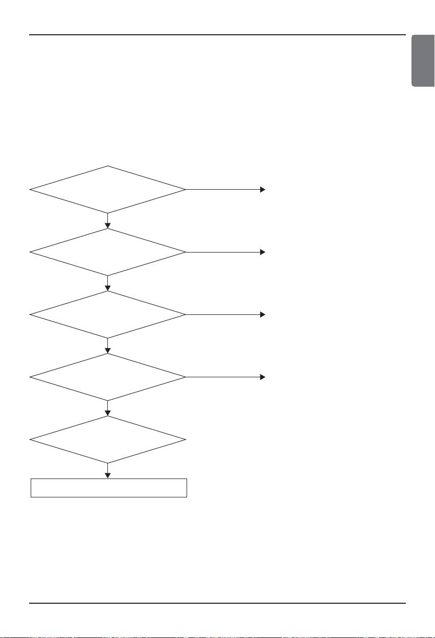
Troubleshooting
- Problem : The TX/RX LED of the LG-NET 1,2,3,4 of the BACnet Gateway is not blinked.
→ The TX/RX LED blinks if normal.
- Expected cause : The power is not applied to the 485 communication terminal
The RS-485 communication polarity is changed
The PI485 DIP switch is not correctly set
The power is not applied to the indoor unit
The address is not correctly set to the indoor unit
- Diagnosis
NO
Is the power is applied
Apply the power to the PI485.
to the PI485?
YES
Is the polarity of the 485
NO
Because the 485 communication has
communication connection
a polarity, the connection should be
line correct?
correctly done.
YES
NO
Is the DIP switch of the
Turn on No. 1 and 4 of the DIP switch.
PI485 correctly set?
YES
NO
Is the power applied to
Apply the power to the indoor unit.
the indoor unit?
YES
Is the power is applied
to the PI485?
NO
Set the address of the indoor unit.
ENGLISH
Installation/Owner Manual 89
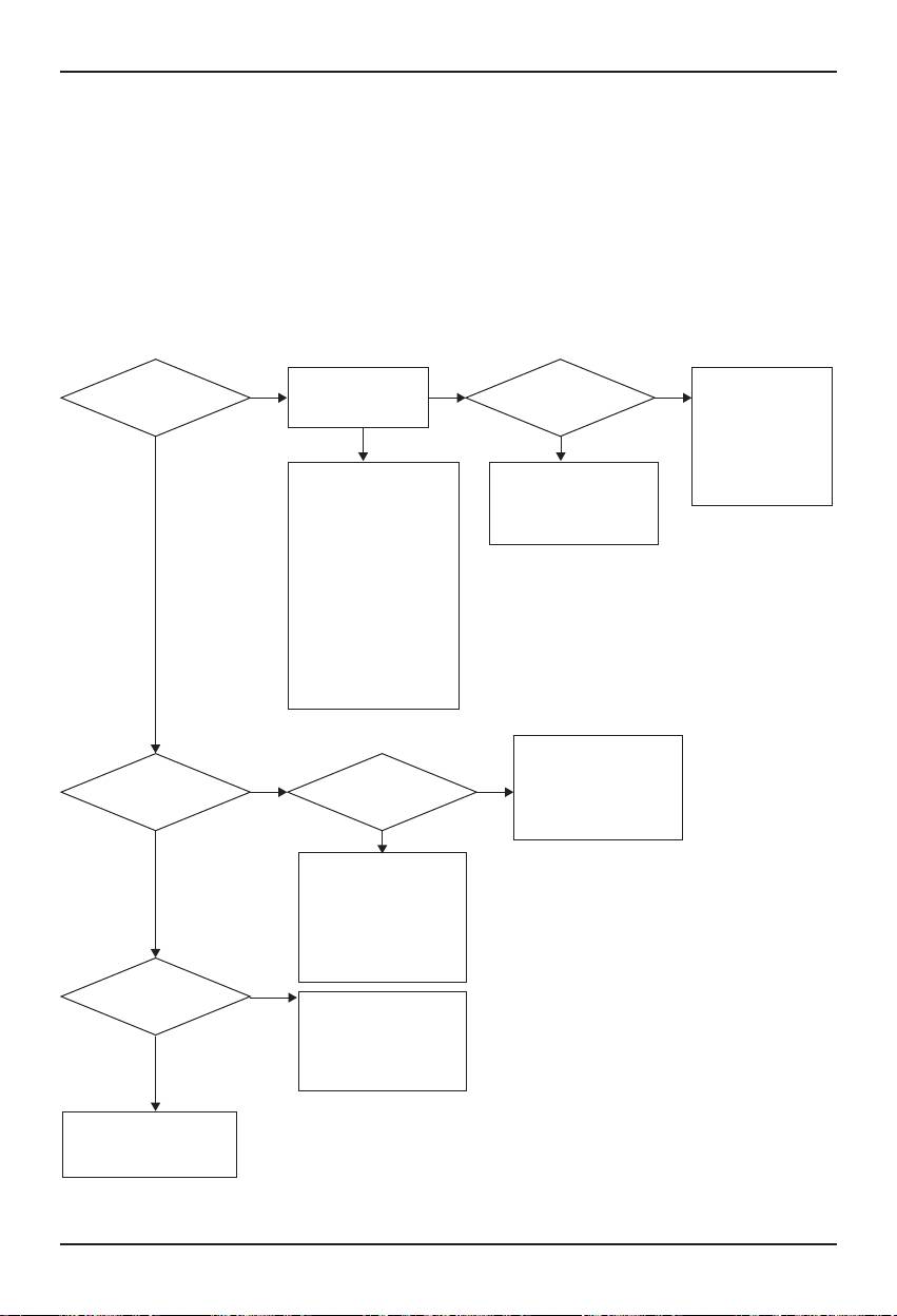
Troubleshooting
- Problem : The indoor unit is not found when checking whether the indoor unit is connected or not by
using the Web Server function.
→ If normal, the indoor units are displayed on the Web Server as many as the number of
the installed indoor units.
- Expected cause : The IP address and the Gateway address of the BACnet Gateway are not
correctly set.
The LAN cable is used incorrectly
The polarity between the PI 485 and the Gateway is changed
- Diagnosis
Perform the PING test
Are all indoor
YES
YES YES
Does the LG-NET LED
Check the
at the command prompt
units not found?
of the BACnet Gateway
communication polarity
window
blinks?
and short/open between
the PI 485 and the
Fail YES
BACnet Gateway and
Check the IP address and the
If it is abnormal after resetting
check the setting of the
Gateway address of the
the BACnet Gateway,
indoor unit address
BACnet Gateway. Check
consider whether to replace
whether the LAN cable is
the BACnet Gateway or not
correct or not (direct cable
when the hub is used, cross
cable when the hub is not
used). Check whether the IP
NO
of the PC can communicate
with the Gateway or not (It is
possible to communicate only
when the first three digits of
the private IP are same)
Check the A/B polarity
between the said PI485 and
Do LED 02G and
Is it not searched for
NO
YES
the Gateway. Check the
03G of the PI485 of the said
each outdoor unit?
outdoor unit keep
number of the outdoor unit
blinking?
and the number of the PI485.
Check the said PI485
connection and the DIP switch.
NO
Check whether the
communication of the
indoor/outdoor unit is normal
or not and check the setting of
the indoor unit address
Is it not searched for
NO
each outdoor unit?
Recheck the setting of the
indoor unit address Make
sure that the communication
of the indoor/outdoor unit is
YES
normal.
Use the PMNFP14A1M by
checking the model name
of the PI485.
90 BACnet Gateway
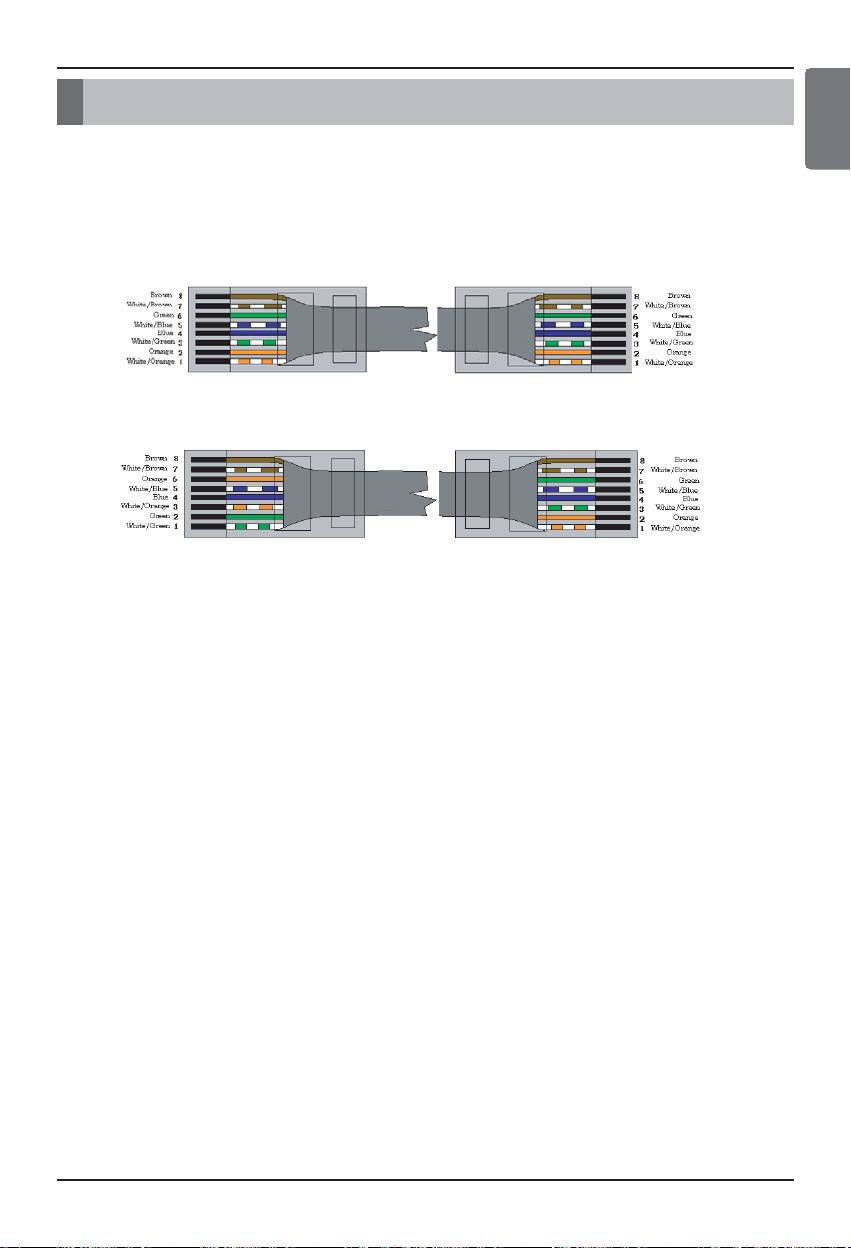
How to differentiate between Direct cable & Cross cable
How to differentiate between Direct cable & Cross cable
Direct Cable - Also called as 1:1 straight cable and used for connecting
other equipment from the network.
Direct cable connection method
Cross Cable – Used for 1:1 connection between same equipment in the network.
Cross cable connection method
ENGLISH
The UTP cable consists of 8 stripes of wire and the wire actually used for data transmission in the
LAN environment is the reception (RX) No.1 and 2 wire and the transmission (TX) No.3 and 6,
consisting of 4 strands. They are classified into two types depending on method to connect wire for
reception and transmission.
Installation/Owner Manual 91

Guide for the open source software
Guide for the open source software
The following GPL/LGPL execution file and library used at this product conform to the GPL/LGPL
license contract.
GPL execution files
Linux kernel 2.4
fdisk
lrzsz
Sysvinit
Inetutils
e2fsprogs
Bash
net-tools
boa http server
busybox
stupid-ftpd
tinylogin
traceroute
LGPL libraries
glibc linuxthreads ncurses zlib
If you request the LG Electronics Co. for the source code via the following e-mail, we will supply them
on the CD-ROM with the fee such as media price and deliverance cost necessary for supplying.
: da_opensource @lge.com
This proposal is effective for three years after getting this product distributed from the LG Electronics
Co.
You can download the original copy of the GPL/LGPL license at http://www.systemaircon.com
Some of the software used at this product conforms to the following copyright.
92 BACnet Gateway

Appendix 1
ENGLISH
Appendix 1
BACnet Interoperability Building Blocks Supported (BIBBs)
• Data Sharing BIBBs
(■ : Supported, ❏ : Unsupported)
BIBB Type Supported BACnet Service Initiate Execute
DS-RP-A Data Sharing-ReadProperty-A ReadProperty -
❏
DS-RP-B Data Sharing-ReadProperty-B ReadProperty -
■
DS-RPM-A Data Sharing-ReadPropertyMultiple-A ReadPropertyMultiple -
❏
DS-RPM-B Data Sharing-ReadPropertyMultiple-B ReadPropertyMultiple -
■
DS-RPC-A Data Sharing-ReadPropertyConditiona-A ReadPropertyConditional -
❏
DS-RPC-B Data Sharing-ReadPropertyConditiona-B ReadPropertyConditional -
❏
DS-WP-A Data Sharing-WriteProperty-A WriteProperty -
❏
DS-WP-B Data Sharing-WriteProperty-B WriteProperty -
■
DS-WPM-A Sharing-WritePropertyMultiple-A WritePropertyMultiple -
❏
DS-WPM-B Data Sharing-WritePropertyMultiple-B WritePropertyMultiple -
-
SubscribeCOV -
DS-COV-A
Data Sharing-COV-A ConfirmedCOVNotification -
❏
UnconfirmedCOVNotification -
SubscribeCOV -
DS-COV-B
Data Sharing-COV-B ConfirmedCOVNotification -
■
UnconfirmedCOVNotification -
SubscribeCOV -
DS-COVP-A
Data Sharing-COVP-A ConfirmedCOVNotification -
❏
UnconfirmedCOVNotification -
SubscribeCOV -
DS-COVP-B
Data Sharing-COVP-B ConfirmedCOVNotification -
❏
UnconfirmedCOVNotification -
DS-COVU-A
Data Sharing-COV-Unsolicited-A UncofirmedCOVNotification -
❏
DS-COVU-B
Data Sharing-COV-Unsolicited-B UncofirmedCOVNotification -
-
Installation/Owner Manual 93

Appendix 1
• Alarm and Event Management BIBBs
(■ : Supported, ❏ : Unsupported)
BIBB Type Supported BACnet Service Initiate Execute
ConfirmedEventNotification -
AE-N-A Alarm and Event-Notification-A
❏
UnconfirmedEventNotification -
ConfirmedEventNotificatioN -
AE-N-I-B Alarm and Event-Notification Internal-B
■
UnconfirmedEventNotification -
ConfirmedEventNotification -
AE-N-E-B Alarm and Event-Notification External-B
❏
UnconfirmedEventNotification -
AE-ACK-A Alarm and Event-ACK-A AcknowledgeAlarm -
❏
AE-ACK-B Alarm and Event-ACK-B AcknowledgeAlarm -
❏
AE-ASUM-A
Alarm and Event-Summary-A GetAlarmSummary -
❏
AE-ASUM-B
Alarm and Event-Summary-B GetAlarmSummary -
❏
AE-ESUM-A
Event-Summary-A GetEnrollmentSummary -
❏
AE-ESUM-B
Event-Summary-B GetEnrollmentSummary -
❏
AE-INFO-A
Alarm and Event-Information-A GetEventInformation -
❏
AE-INFO-B
Alarm and Event-Information-B GetEventInformation -
❏
AE-LS-A Alarm and Event-LifeSafety-A LifeSafetyOperation -
❏
AE-LS-B Alarm and Event-LifeSafety-B LifeSafetyOperation -
❏
• Scheduling BIBBs
(■ : Supported, ❏ : Unsupported)
BIBB Type Supported BACnet Service Initiate Execute
Scheduling-A
SCHED-A
❏
(must support DS-RP-A and DS-WP-A)
Scheduling-Internal-B
SCHED-I-B
(shall support DS-RP-B and DS-WP-B)
❏
(shall also support ether DM-TS-B or DS-UTC-B)
Scheduling-External-B
SCHED-E-B
❏
(shall support SCHED-I-B and DS-WP-A)
94 BACnet Gateway

Appendix 1
ENGLISH
• Trending BIBBs
(■ : Supported, ❏ : Unsupported)
BIBB Type Supported BACnet Service Initiate Execute
T-VMT-A
Trending - Viewing and Modifying Trends-A
❏
ReadRange -
T-VMT-I-B
Trending - Viewing and Modifying Trends Internal-B
❏
ReadRange -
T-VMT-E-B
Trending - Viewing and Modifying Trends External-B
❏
ReadRange -
ConfirmedEventNotification -
T-ATR-A Trending - Automated Trend Retrieval-A
❏
ReadRange -
ConfirmedEventNotification -
T-ATR-B Trending - Automated Trend Retrieval-B
❏
ReadRange -
• Device Management BIBBs (1)
(■ : Supported, ❏ : Unsupported)
BIBB Type Supported BACnet Service Initiate Execute
Who-Is -
DM-DDB-A
Device Management – Dynamic Device , Binding-A
■
I-Am -
Who-Is -
DM-DDB-B
Device Management - Dynamic Device , Binding-B
■
I-Am -
Who-Has -
DM-DOB-A
Device Management - Dynamic Object , Binding-A
❏
I-Have -
Who-Has -
DM-DOB-B
Device Management - Dynamic Object , Binding-B
■
I-Have -
DM-DCC-A
Device Management - DeviceCommunicationControl-A
❏
DeviceCommunicationControl -
DM-DCC-B
Device Management - DeviceCommunicationControl-B
❏
DeviceCommunicationControl -
ConfirmedPrivateTransfer -
DM-PT-A Device Management - PrivateTransfer-A
❏
UnconfirmedPrivateTransfer -
ConfirmedPrivateTransfer -
DM-PT-B Device Management - PrivateTransfer-B
❏
UnconfirmedPrivateTransfer -
ConfirmedPrivateTransfer -
DM-TM-A Device Management - Text Message-A
❏
UnconfirmedPrivateTransfer -
ConfirmedPrivateTransfer -
DM-TM-B Device Management - Text Message-B
❏
UnconfirmedPrivateTransfer -
DM-TS-A
Device Management - TimeSynchronization-A
❏
TimeSynchronization -
DM-TS-B
Device Management - TimeSynchronization-B
■
TimeSynchronization -
DM-UTC-A
Device Management - UTCTimeSynchronization-A
❏
UTCTimeSynchronization -
DM-UTC-B
Device Management - UTCTimeSynchronization-B
■
UTCTimeSynchronization -
DM-RD-A Device Management - ReinitializeDevice-A ReinitializeDevice -
❏
DM-RD-B Device Management -ReinitializeDevice-B ReinitializeDevice -
❏
Installation/Owner Manual 95

Appendix 1
• Device Management BIBBs (2)
(■ : Supported, ❏ : Unsupported)
BIBB Type Supported BACnet Service Initiate Execute
AtomicReadFile -
Device Management - Backup and AtomicWriteFile -
❏
DM-BR-A
Restore-A CreateObject -
ReinitializeDevice -
AtomicReadFile -
Device Management - Backup and
DM-BR-B
❏
AtomicWriteFile -
Restore-B
ReinitializeDevice -
DM-R-A Device Management - Restart-A UnconfimedCOVNotification -
❏
DM-R-B Device Management - Restart-B UnconfimedCOVNotification -
❏
❏
AddListElement -
DM-LM-A Device Management - List Manipulation-A
RemoveListElement -
■
AddListElement -
DM-LM-B Device Management - List Manipulation-B
RemoveListElement -
❏
CreateObject -
DM-OCD-A
Device Management - Object Creation and Deletion-A
DeleteObject -
❏
CreateObject -
DM-OCD-B
Device Management - Object Creation and Deletion-B
DeleteObject -
VT-Open -
DM-VT-A Device Management - Virtual Terminal-A VT-Close - -
❏
VT-Data - -
VT-Open -
DM-VT-B Device Management - Virtual Terminal-B VT-Close - -
❏
VT-Data - -
96 BACnet Gateway

Appendix 1
ENGLISH
• Network Management BIBBs
(■ : Supported, ❏ : Unsupported)
BIBB Type Supported BACnet Service Initiate Execute
Network Management - Connection
Establish-Connection-To-Network
-
NM-CE-A
❏
Establishment-A
Disconnect-Connection-To-Network
-
Network Management - Connection
Establish-Connection-To-Network
-
NM-CE-B
❏
Establishment-B
Disconnect-Connection-To-Network
-
Who-Is-Router-To-Network -
I-Am-Router-To-Network -
Network Management - Router
NM-RC-A
I-Could-Be-Router-To-Network -
Configuration-A
❏
Initialize-Routing-Table -
Initialize-Routing-Table-Ack -
Who-Is-Router-To-Network - -
Network Management - Router I-Am-Router-To-Network - -
NM-RC-B
❏
Configuration-B Initialize-Routing-Table -
Initialize-Routing-Table-Ack -
Installation/Owner Manual 97

Appendix 2
Appendix 2
Obejct Property table
O : indicates that the property is optional.
R : indicates that the property is required to be present and readable using BACnet services.
W : indicates that the property is required to be present, readable, and writable using BACnet
services.
• Analog Input Object Type (1)
Property Identifier Property Datatype BACnet BNU-BAC
Object_Identifier BACnetObjectIdentifier R R
Object_Name CharacterString R R
Object_Type BACnetObjectType R R
Present_Value Real R1 R
Description CharacterString O R
Device_Type CharacterString O -
Status_Flags BACnetStatusFlags R R
Event_State BACnetEventState R R
Reliability BACnetReliability O -
Out_Of_Service BOOLEAN R R
Update_Interval Unsigned O -
Units BACnetEngineeringUnits R R
Min_Pres_Value REAL O -
Max_Pres_Value REAL O -
Resolution REAL O -
COV_Increment REAL O2 -
Time_Delay Unsigned O3 -
Notification_Class Unsigned O3 -
High_Limit Real O3 -
Low_Limit Real O3 -
Deadband Real O3 -
Limit_Enable BACnetLimitEnable O3 -
Event_Enable BACnetEventTransitionBits O3 -
Acked_Transitions BACnetEventTransitionBits O3 -
Notify_Type BACnetNotifyType O3 -
Event_Time_Stamps
BACnetARRAY[3] of BACnetTimeStamp
O3 -
Profile_Name CharacterString O -
98 BACnet Gateway

Appendix 2
ENGLISH
• Analog Value Object Type
Property Identifier Property Datatype BACnet BNU-BAC
Object_Identifier BACneObjectIdentifier R R
Object_Name CharacterString R R
Object_Type BACnetObjectType R R
Present_Value Real R4 W
Description CharacterString O R
Status_Flags BACnetStatusFlags R R
Event_State BACnetEventState R R
Reliability BACnetReliability O -
Out_Of_Service Boolean R R
Units BACnetEngineeringUnits R R
PriorityArray BACnetPriorityArray O1 -
RelinquishDefault Real O1 -
COV_Increment Real O2 -
Time_Delay Unsigned O3 -
Notification_Class Unsigned O3 -
High_Limit REAL O3 -
Low_Limit REAL O3 -
Deadband REAL O3 -
Limit_Enable BACnetLimitEnable O3 -
Event_Enable BACnetEventTransitionBits O3 -
Acked_Transitions BACnetEventTransitionBits O3 -
Notify_Type BACnetNotifyType O3 -
Event_Time_Stamps
BACnetARRAY[3] of BACnetTimeStamp
O3 -
Profile_Name CharacterString O -
Installation/Owner Manual 99

Appendix 2
• Binary Input Object Type
Property Identifier Property Datatype BACnet BNU-BAC
Object_Identifier BACneObjectIdentifier R R
Object_Name CharacterString R R
Object_Type BACnetObjectType R R
Present_Value BACnetBinaryPV R1 R
Description CharacterString O R
Device_Type CharacterString O -
Status_Flags BACnetStatusFlags R R
Event_State BACnetEventState R R
Reliability BACnetReliability O -
Out_Of_Service Boolean R R
Polarity BACnetPolarity R R
Inactive_Text CharacterString O2 -
Active_Text CharacterString O2 -
Change_Of_State_Time BACnetDateTime O3 -
Change_Of_State_Count Unsigned O3 -
Time_Of_State_Count_Reset
BACnetDateTime O3 -
Elapsed_Active_Time Unsigned32 O4 -
Time_Of_Active_Time_Reset
BACnetDateTime O5 -
Time_Delay Unsigned O5 -
Notification_Class Unsigned O5 -
Alarm_Value BACnetBinaryPV O5 -
Event_Enable BACnetEventTransitionBits O5 -
Acked_Transitions BACnetEventTransitionBits O5 -
Notify_Type BACnetNotifyType O5 -
Event_Time_Stamps
BACnetARRAY[3] of BACnetTimeStamp
O5 -
Profile_Name CharacterString O -
100 BACnet Gateway

Appendix 2
ENGLISH
• Binary Output Object Type
Property Identifier Property Datatype BACnet BNU-BAC
Object_Identifier BACneObjectIdentifier R R
Object_Name CharacterString R R
Object_Type BACnetObjectType R R
Present_Value BACnetBinaryPV W W
Description CharacterString O R
Device_Type CharacterString O -
Status_Flags BACnetStatusFlags R R
Event_State BACnetEventState R R
Reliability BACnetReliability O -
Out_Of_Service Boolean R R
Polarity BACnetPolarity R R
Inactive_Text CharacterString O1 -
Active_Text CharacterString O1 -
Change_Of_State_Time BACnetDateTime O2 -
Chgange_Of_State_Count Unsigned O2 -
Time_Of_State_Count_Reset
BACnetDateTime O2 -
Elapsed_Active_Time Unsigned32 O3 -
Time_Of_Active_Time_Reset
BACnetDateTime O3 -
Minimum_Off_Time Unsigned32 O -
Minimum_On_Time Unsigned32 O -
Priority_Array BACnetPriorityArray R R
Relinquish_Default BACnetBinaryPV R R
Time_Delay Unsigned O4 -
Notification_Class Unsigned O4 -
Feedback_Value BACnetBinaryPV O4 -
Event_Enable BACnetEventTransitionBits O4 -
Acked_Transitions BACnetEventTransitionBits O4 -
Notify_Type BACnetNotifyType O4 -
Event_Time_Stamps
BACnetARRAY[3] of BACnetTimeStamp
O4 -
Profile_Name CharacterString O -
Installation/Owner Manual 101

Appendix 2
• Binary Value Object Type
Property Identifier Property Datatype BACnet BNU-BAC
Object_Identifier BACneObjectIdentifier R R
Object_Name CharacterString R R
Object_Type BACnetObjectType R R
Present_Value BACnetBinaryPV R1 W
Description CharacterString O R
Status_Flags BACnetStatusFlags R R
Event_State BACnetEventState R R
Reliability BACnetReliability R -
Out_Of_Service Boolean R R
Inactive_Text CharacterString O2 -
Active_Text CharacterString O2 -
Change_Of_State_Time BACnetDateTime O3 -
Chgange_Of_State_Count Unsigned O3 -
Time_Of_State_Count_Reset
BACnetDateTime O3 -
Elapsed_Active_Time Unsigned32 O4 -
Time_Of_Active_Time_Reset
BACnetDateTime O4 -
Minimum_Off_Time Unsigned32 O -
Minimum_On_Time Unsigned32 O -
Priority_Array BACnetPriorityArray O5 -
Relinquish_Default BACnetBinaryPV O5 -
Time_Delay Unsigned O6 -
Notification_Class Unsigned O6 -
Alarm_Value BACnetBinaryPV O6 -
Event_Enable BACnetEventTransitionBits O6 -
Acked_Transitions BACnetEventTransitionBits O6 -
Notify_Type BACnetNotifyType O6 -
Event_Time_Stamps BACnetARRAY[3] of BACnetTimeStamp O6 -
Profile_Name CharacterString O -
102 BACnet Gateway

Appendix 2
ENGLISH
• Device Object Type (1)
Property Identifier Property Datatype BACnet BNU-BAC
Object_Identifier BACneObjectIdentifier R R
Object_Name CharacterString R R
Object_Type BACnetObjectType R R
System_Status BACnetDeviceStatus R R
Vendor_Name CharacterString R R
Vendor_Identifier Unsigned16 R R
Model_Name CharacterString R R
Firmware_Revision CharacterString R R
Application_Software_Version CharacterString R R
Location CharacterString O R
Description CharacterString O R
Protocol_Version Unsigned R R
Protocol_Conformance_Class Unsigned(1…6) R R
Protocol_Services_Supported BACnetServiceSupported R R
Protocol_Object_Types_Supp orted
BACnetObjectTypesSupported R R
Object_List
BACnetARRAY[N] of BACnetObjectIdentifier
RR
Max_APDU_Length_Accepted Unsigtned R R
Segmentation_Supported BACnetSegmentation R R
VT_Class_Supported List of BACnetVTClass _1 -
Active_VT_Sessions List of BACnetVTSession _2 -
Installation/Owner Manual 103

Appendix 2
• Device Object Type (2)
Property Identifier Property Datatype BACnet BNU-BAC
Local_Time Time O3, 4 -
Local_Date Date O3, 4 -
UTC_Offset Signed O4 R
Daylight_Saving_Status Boolean O4 -
APDU_Segment_Timeout Unsigned O1 -
APDU_Timeout Unsigned R R
Number_Of_APDU_Retries Unsigned R R
List_Of_Session_Keys List of BACnetSessionKey O -
Time_Synchronization_Recipients
List of BACnetRecipient O5 -
Max_Master Unsigned(1…127) O6 -
Max_Info_Frames Unsigned O6 -
Device_Adress_Binding List of BACnetAddressBinding R R
Database_Revision Unsigned R R
Configuration_Files
BACnetARRAY[N] of BACnetObjectIdentifier
O7 -
Last_Restore_Time BACnetDateTime O7 -
Backup_Failure_Timeout Unsigned16 O8 -
Active_COV_Subscriptions List of BACnetCOVSubscription O9 -
Profile_Name CharacterString O R
104 BACnet Gateway

Appendix 2
ENGLISH
• Multi-state Input Object Type
Property Identifier Property Datatype BACnet BNU-BAC
Object_Identifier BACneObjectIdentifier R R
Object_Name CharacterString R R
Object_Type BACnetObjectType R R
Present_Value Unsigned R1 R
Description CharacterString O R
Device_Type CharacterString O -
Status_Flags BACnetStatusFlags R R
Event_State BACnetEventState R R
Reliability BACnetReliability O2 -
Out_Of_Service Boolean R R
Number_Of_States Unsigned R R
State_Text BACnetARRAY[N] of CharacterString O -
Time_Delay Unsigned O3 -
Notification_Class Unsigned O3 -
Alarm_Values List of Unsigned O3 -
Fault_Values List of Unsigned O3 -
Event_Enable BACnetEventTransitionBits O3 -
Acked_Transitions BACnetEventTransitionBits O3 -
Notify_Type BACnetNotifyType O3 -
Event_Time_Stamps BACnetARRAY[3] of BACnetTimeStamp O3 -
Profile_Name CharacterString O -
Installation/Owner Manual 105

Appendix 2
• Multi-state Output Object Type
Property Identifier Property Datatype BACnet BNU-BAC
Object_Identifier BACneObjectIdentifier R R
Object_Name CharacterString R R
Object_Type BACnetObjectType R R
Present_Value Unsigned W W
Description CharacterString O R
Device_Type CharacterString O -
Status_Flags BACnetStatusFlags R R
Event_State BACnetEventState R R
Reliability BACnetReliability O -
Out_Of_Service Boolean R R
Number_Of_States Unsigned R R
State_Text BACnetARRAY[N] of CharacterString O -
Priority_Array BACnetPriorityArray R R
Relinquish_Default Unsigned R R
Time_Delay Unsigned O1 -
Notification_Class Unsigned O1 -
Feedback_Value Unsigned O1 -
Event_Enable BACnetEventTransitionBits O1 -
Acked_Transitions BACnetEventTransitionBits O1 -
Notify_Type BACnetNotifyType O1 -
Event_Time_Stamps BACnetARRAY[3] of BACnetTimeStamp O1 -
Profile_Name CharacterString O -
106 BACnet Gateway

Appendix 3
ENGLISH
Appendix 3
BACnet Gateway Error Response Table
• Error PDU
Error PDU Error CodeError Class
Reading of the object list during the initialization
Device(0) Configuration_In_Progress(2)
of the LG-NET
Request to access to an object not installed.
Object(1) Unknown_Object(31)
Request to access to a property not installed.
Property(2) Unknown_Property(32)
Request to write to a prohibited area.
Property(2) Write_Access_Denied(40)
Request to write in a format different from the
Property(2) Invalid_Datatype(9)
property.
Request to access to a specified index outside
Property(2) Invalid_Array_Index(42)
the array index range.
Request to write a value outside the permissible
Property(2) Value_Out_Of_Range(37)
range.
A COV registration request of more than 10
Resource(3) Other(0)
registration items.
An Event registration request of more than 10
Resource(3)
No_Space_To_Add_List_Element(19)
registration items.
Request for the deletion of an element not
Service(5) Other(0)
existing in the list.
Request for the execution of the
AddListElement/RemoveListElement for a
Service(5) Property_Is_Not_List(22)
property that is not of List type.
• Reject PDU
Reject PDU Reject Reason
A propertyID or value overflow or underflow occurred during
Inconsistent_Parameter(2)
WritePropertyMultiple operation.
The type of parameter for the execution of the service is different in
Invalid_Parameter_Data_Type(3)
type.
An error was detected during tag decoding.
Invalid_Tag(4)
A parameter shortage occurred during the execution of the service.
Missing_Required_Parameter(5)
Too many arguments for the execution of the service.
Too_Many_Arguments(7)
An attempt to execute an unsupported service with confirmation.
Unrecognized_Service(9)
• Abort PDU
Abort PDU Abort Reason
Unable to process due to too many requests beyond the capacity.
Buffer_Overflow(1)
The processing of segments was aborted because an expected
Invalid_APDU_In_This_State(2)
APDU was received.
The response side does not support the segment.
Segmentation_Not_Supported(4)
Installation/Owner Manual 107

108 BACnet Gateway
