Karcher KM 90-60 R Lpg Adv: Maintenance and care
Maintenance and care: Karcher KM 90-60 R Lpg Adv
-
8
Switch off the appliance and remove
the ignition key prior to performing any
cleaning or maintenance tasks on the
appliance, replacing parts or switching
over to another function.
Always disconnect the battery when
working on the electrics.
–
Maintenance work may only be carried
out by approved customer service out-
lets or experts in this field who are famil-
iar with the respective safety
regulations.
–
Mobile appliances used for commercial
purposes are subject to safety inspec-
tions according to VDE 0701.
–
Use only roller brushes/ side-brushes
that are provided with the appliance or
specified in the Operations Manual.
The use of other roller brushes/ side-
brushes can affect the safety of the ap-
pliance.
–
The battery installed in the appliance is
maintenance-free.
Caution
Risk of damage! Do not clean the appliance
with a water hose or high-pressure water
jet (danger of short circuits or other dam-
age).
Do not use aggressive and abrasive clean-
ing agents.
Danger
Risk of injury! Wear dust mask and protec-
tive goggles.
Open the device hood.
Blow through machine with com-
pressed air.
Clean the machine with a damp cloth
which has been soaked in mild deter-
gent.
Close cover.
Clean the machine with a damp cloth
which has been soaked in mild deter-
gent.
Observe the inspection checklist!
Note:
The elapsed-time counter shows the
timing of the maintenance intervals.
Note:
Where maintenance is carried out by
the customer, all service and maintenance
work must be undertaken by a qualified
specialist. If required, a specialised Kärch-
er dealer may be contacted at any time.
Note:
For description, see section on Main-
tenance work.
Daily maintenance:
Check engine oil level.
Check tyre pressure.
Check fill level of hydraulic oil.
Check function of all operator control el-
ements.
Check function of seat contact switch.
Weekly maintenance:
Check gas pipes.
Check air filter.
Check moving parts for freedom of
movement.
Check the sealing strips in the sweep-
ing area for position and wear.
Check dust filter and clean filter box, if
required.
Maintenance to be carried out every 100
operating hours:
Change engine oil (initial change after
20 operating hours).
Check spark plug.
Check tension, wear and function of
drive belts (V-belt and circular belt).
Clean air filter.
Maintenance following wear:
Replace sealing strips.
Replace roller brush.
Replace side brush.
Note:
In order to safeguard warranty claims,
all service and maintenance work during the
warranty period must be carried out by the
authorised Kärcher Customer Service in ac-
cordance with the maintenance booklet.
Maintenance to be carried out after 20
operating hours:
Carry out initial inspection.
Maintenance to be carried out every 100
operating hours
Have maintenance tasks performed ac-
cording to the inspection check list.
Maintenance to be carried out every 200
operating hours
Have maintenance tasks performed ac-
cording to the inspection check list.
Maintenance to be carried out every 300
operating hours
Have maintenance tasks performed ac-
cording to the inspection check list.
Danger
Risk of injury!
The engine requires approx. 3-4 seconds
to come to a standstill once it has been
switched off. During this time, stay well
clear of the working area.
Risk of burns!
Allow the machine sufficient time to cool
down before carrying out any maintenance
and repair work.
Caution
Please do not release engine oil, fuel oil,
diesel and petrol into the environment. Pro-
tect the ground and dispose of used oil in
an environmentally-clean manner.
Park the sweeper on an even surface.
Turn ignition key to "0" and remove it.
Allow device to cool down sufficiently.
For certain maintenance tasks (e.g. change
of the battery) it is necessary to the remove
the rear panel first.
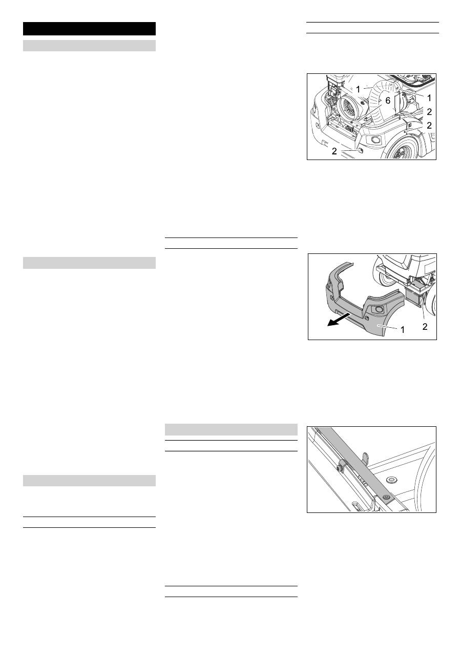
Open the device hood.
1 Screws suction blower hose
2 Screws rear panel
Loosen the 2 screws at the suction
blower hose and pull off the suction
hose.
Loosen all 6 screws on the left side,
right side, and at the back of the rear
panel.
Close cover.
1 Tail panel
2 Battery
Remove the rear panel together with
the suction blower hose towards the
back.
When installing the rear panel, ensure
that the retaining strap is always locat-
ed above the sheet metal bracket.
Maintenance and care
General notes
Cleaning
Cleaning the inside of the machine
External cleaning of the appliance
Maintenance intervals
Maintenance by the customer
Maintenance by Customer Service
Maintenance Works
General notes on safety
Preparation
Remove rear panel
24 EN
-
9
Please observe the following warning notes
when handling batteries:
Danger
Risk of explosion! Do not put tools or similar
on the battery, i.e. on the terminal poles
and cell connectors.
Danger
Risk of injury! Ensure that wounds never
come into contact with lead. Always clean
your hands after having worked with batter-
ies.
Danger
Risk of fire and explosion!
–
Smoking and naked flames are strictly
prohibited.
–
Rooms where batteries are charged
must have good ventilation because
highly explosive gas is emitted during
charging.
Danger
Danger of causticization!
–
Rinse thoroughly with lots of clear water
if acid gets into the eye or comes in con-
tact with the skin.
–
Then consult a doctor immediately.
–
Wash off the acid If it comes in contact
with the clothes.
–
Change clothing.
Remove the tail panel.
Refer to Chapter "Maintenance tasks/
removing the rear panel".
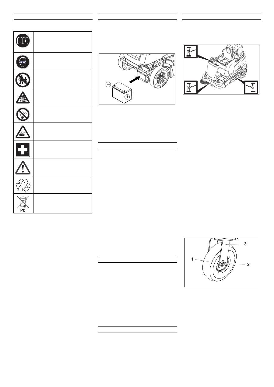
Insert battery in battery mount.
Note
: Observe the mounting direction
concerning the polarity of the connection!
Connect pole terminal (red cable) to
positive pole (+).
Connect pole terminal to negative pole
(-).
Note:
Check that the battery pole and pole
terminals are adequately protected with
pole grease.
Danger
Risk of injury! Comply with safety regula-
tions on the handling of batteries. Observe
the directions provided by the manufacturer
of the charger.
Danger
Charge the battery only with an appropriate
charger.
Disconnect battery.
Connect positive terminal cable from
the charger to the positive pole connec-
tion on the battery.
Connect negative terminal cable from
the charger to the negative pole con-
nection on the battery.
Plug in mains connector and switch on
charger.
Note:
When the battery is charged, first re-
move the charger from the mains and then
disconnect it from the battery.
Remove the tail panel.
Disconnect pole terminal to negative
pole (-).
Disconnect pole terminal to positive
pole (-).
Remove the battery from the battery
holder.
Used batteries are to be disposed ac-
cording to the EC guideline 91/ 157
EWG or the corresponding national
regulations in an environment-friendly
manner.
Park the sweeper on an even surface.
Connect air pressure testing device to
tyre valve.
Check air pressure and adjust if re-
quired.
For permissible tyre inflation pressure
see Chapter "Technical specifications".
Park the sweeper on an even surface.
Remove ignition key.
Check stability of ground. Lock the ap-
pliance to ensure that it does not roll off.
Position vehicle jack at the appropriate
mounting point for the front or rear
wheel.
Note
Use a suitable commercially available vehi-
cle jack.
Loosen the wheel nuts/wheel bolts by
about 1 revolution using a suitable tool.
Replace the rear wheel
Raise slightly the waste container on
the appropriate side and pull it out.
Raise machine using vehicle jack.
Unscrew the wheel nuts/wheel bolts
and remove them.
Remove wheel.
Have the defective wheel repaired by a
specialised repair shop.
Place the wheel and screw in the wheel
nuts/wheel bolts all the way; tighten
them lightly.
Lower machine using vehicle jack.
Torque the wheel nuts/wheel bolts to
the required torque.
Push in the waste container and lock it.
Replace the front wheel
1 Front wheel
2 Nut
3 Intake
Raise machine using vehicle jack.
Loosen both screws on the wheel axle
by 1-2 rotations. If necessary, hold up a
second wrench to loosen them.
Remove the wheel together with the ax-
le.
Have the defective wheel repaired by a
specialised repair shop.
Tighten the repaired front wheel with
the axle and nut to the retainer.
Lower machine using vehicle jack.
Safety notes regarding the batteries
Observe the directions on the
battery, in the instructions for
use and in the vehicle operat-
ing instructions!
Wear an eye shield!
Keep away children from acid
and batteries!
Risk of explosion!
Fire, sparks, open light, and
smoking not allowed!
Danger of causticization!
First aid!
Warning note!
Disposal!
Do not throw the battery in the
dustbin!
Installing and connecting the battery
Charging battery
Remove the battery
Check the tyre pressure
Replacing wheel
Tightening torque (Nm)
56 Nm
25 EN
-
10
Danger
Risk of burns on account of hot surfaces!
Allow engine to cool down.
Wait for at least 5 minutes after switch-
ing off the engine before checking the
engine oil fill level.
Open the device hood.
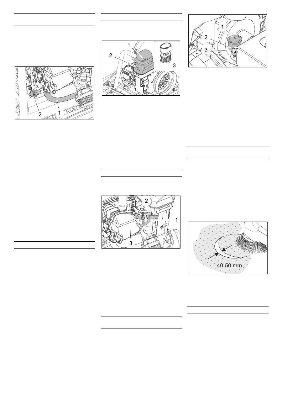
1 Oil drain hose
2 Oil dipstick
Unscrew and withdraw oil dipstick.
Wipe off and insert the oil dipstick (do
not turn it in).
Remove the oil dip one more time and
check the oil level.
–
The oil level must lie between “MIN“
and “MAX“ marking.
–
Add motor oil if the oil level is below the
"MIN" marking.
–
Do not fill oil above the "MAX" marking.
Fill motor oil into the oil fill neck.
Note
: For filling in the motor oil, use ac-
cessories such as a bent funnel tube or
an oil-change pump 6.491-538.
For oil type refer to Chapter "Technical
specifications".
Wait at least 5 minutes.
If the engine oil level is correct, screw in
the oil dipstick.
Danger
Risk of burns due to hot oil!
Allow engine to cool down.
Open the device hood.
Ready a catch bin for appr. 1 litre oil.
Unscrew the locking screw of the oil
drain hose and drain the oil.
Screw in the locking screw and tighten
it again.
Unscrew and withdraw oil dipstick.
Fill motor oil into the oil fill neck.
For oil type and filling quantity refer to
Chapter "Technical specifications".
Wait at least 5 minutes.
Check engine oil level.
If the engine oil level is correct, screw in
the oil dipstick.
Deliver the old oil to the respective col-
lection centres.
Danger
Risk of burns on account of hot surfaces!
Allow engine to cool down.
1 Wing bolt
2 Air filter housing
3 Filter inlay
Remove the wing screw.
Remove the air filter housing.
Take out the filter inlay.
Clean the interior of the air filter reser-
voir.
Clean or replace the filter inlay.
Install a new filter inlay.
Fit the air filter casing and secure it by
means of the butterfly nut.
Caution
Risk of injury! Do not remove the spark plug
connector manually.
1 Vacuum line
2 Ignition plug
3 Casing
Pull the vacuum line out of the casing.
Remove the spark plug connector using
suitable tools/tongs.
Unscrew and clean spark plug.
Screw in cleaned or new spark plug.
Push on spark-plug connector.
Reinsert the vacuum pipe into the cas-
ing.
Danger
Risk of burns on account of hot surfaces!
Caution
This inspection may only be carried out
when the engine is warm
Open the device hood.
1 Equalising container
2 MAX oil level
3 MIN oil level
Check oil level in the equalisation con-
tainer.
The filling level should be between the
"Max" and "Min" marking.
If hydraulic oil is missing:
Remove the lid of the equalising reser-
voir and refill hydraulic oil.
For oil type refer to Chapter "Technical
specifications".
Close the lid.
Check tyre pressure.
The side-brushes lift up.
Drive sweeper on to a smooth, even
surface covered with a visible layer of
dust or chalk.
Lower side-brushes and allow them to
briefly rotate.
The side-brushes lift up.
Drive machine backwards.
Park the sweeper on an even surface.
Check sweeping mirror.
The width of the sweeping track should lie
between 40-50 mm.
Note:
The side brush floating mounting ad-
justs the sweeping track as the bristles
wear down. The side brush must be re-
placed if it becomes too worn.
Park the sweeper on an even surface.
Set programme switch to step 1 (driv-
ing). Side brushes lift up.
Turn ignition key to "0" and remove it.
Loosen 3 fastening screws on the un-
derside.
Remove the wiper blade.
Clip new side brushes on to driver and
screw on.
Check engine oil level and top up, if re-
quired
Change the engine oil
Change the air filter
Clean or replace the spark plug
Check hydraulic oil level and refill hy-
draulic oil
Checking the sweeping mirror of the
side-brushes
Replacing side brush
26 EN
-
11
Park the sweeper on an even surface.
Set programme switch to step 1 (driv-
ing). Roller brush is raised.
Turn ignition key to "0" and remove it.
Secure the machine with wheel
chock(s) to prevent it from rolling away.
Remove belts or cords from roller
brush.
Note:
The side brush floating mounting of
the roller brush adjusts the sweeping track
as the bristles wear down. The roller brush
must be replaced if it becomes too worn.
Set programme switch to step 1 (driv-
ing). The side brush and roller brush are
raised.
Drive sweeper on to a smooth, even
surface covered with a visible layer of
dust or chalk.
Lower roller brush and allow it to briefly
rotate.
Raise roller brush.
Press pedal which raises bulk waste
flap and keep pressed.
Drive machine backwards.
The sweeping track should have an even rectan-
gular shape which is between 50 and 70 mm
wide.
Replacement is due if a visible deteriora-
tion in sweeping performance caused by
bristle wear is evident.
Park the sweeper on an even surface.
Set programme switch to step 1 (driv-
ing). Roller brush is raised.
Turn ignition key to "0" and remove it.
Secure the machine with wheel
chock(s) to prevent it from rolling away.
Raise slightly the waste container on
the left side and pull it out.
Loosen the fastening screw on the left
side-panel.
Remove side panel.
Hook the draw spring out.
1 Fastening screw of the under-pressure
can
2 Fastening nut of the bulk waste flap
3 Screw of the roller brush crank
Unscrew the fastening screws of the
vacuum socket and release the lever.
Turn the fastening nut of the bulk waste
flap and unhook the bulk waste flap.
Unscrew and withdraw bolt on the roller
brush swinging arm.
Push the roller brush cover backwards
and remove it.
Pull out roller brush.
Push new roller brush into the roller
brush housing and onto the drive pin.
Note:
When installing the new roller
brush, ensure correct positioning of the
bristle assembly.
Installation position of roller brush in direction of
travel
Position roller brush cover.
Fit the fastening screws and nuts.
Hook the draw spring in.
Screw on side panel.
Push in the waste containers on both
the sides and lock them.
Park the sweeper on an even surface.
Set programme switch to step 1 (driv-
ing). Roller brush is raised.
Turn ignition key to "0" and remove it.
Secure the machine with wheel
chock(s) to prevent it from rolling away.
Raise slightly the waste containers on
both sides and pull them out.
Open the fastening screws of the side
panels on both sides.
Remove side panels.
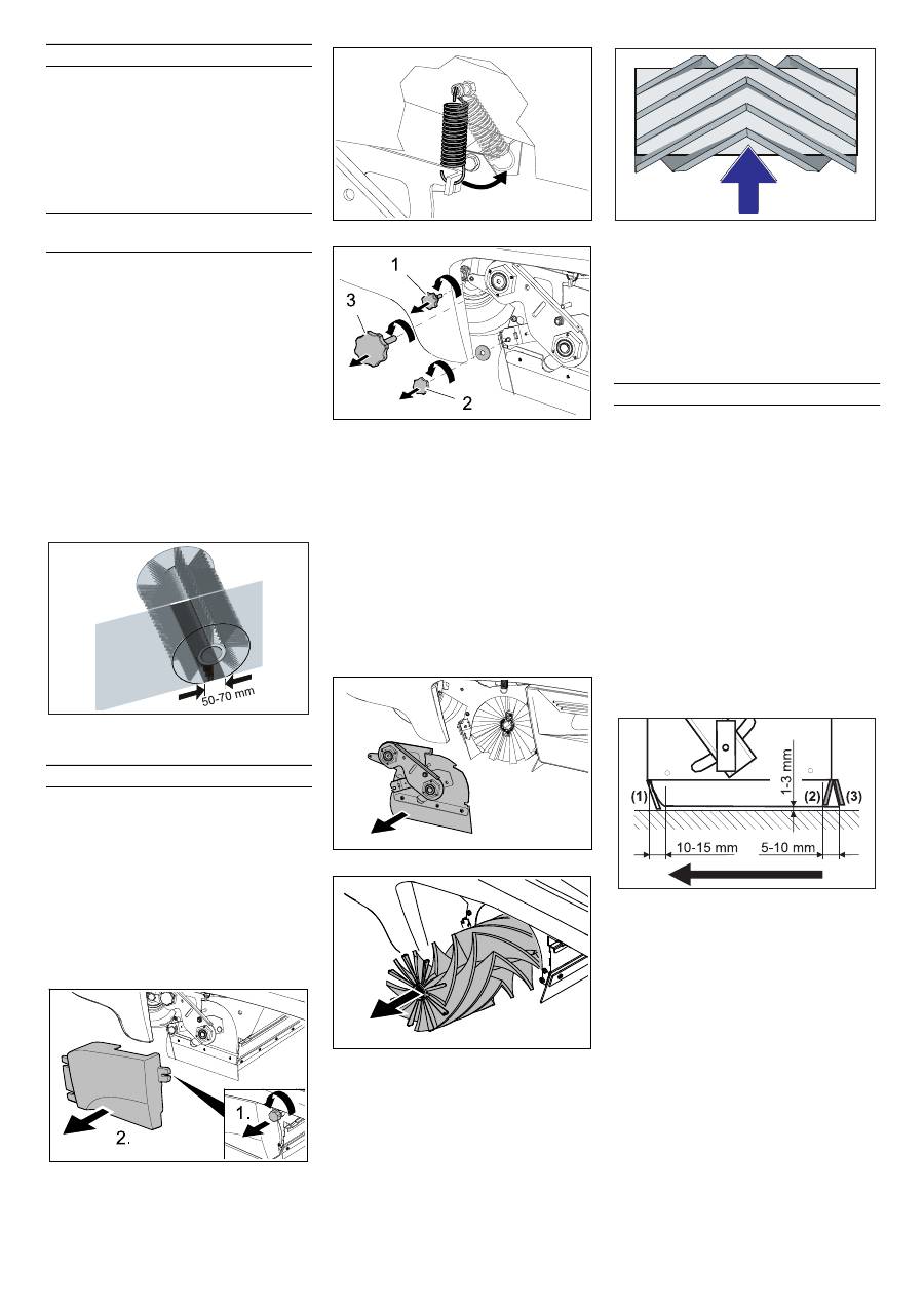
Front sealing strip
Loosen retaining nuts for the front seal-
ing strip (1) slightly (to replace, un-
screw).
Screw on new sealing strip without fully
tightening the nuts.
Adjust sealing strip.
Set the distance between the sealing
strip and the floor so that the bottom
edge trails behind at a distance of be-
tween 10-15 mm.
Tighten nuts.
Rubber strip
If worn, replace.
Unscrew retaining nuts for the rubber
strip (2).
Screw on new rubber strip.
Rear sealing strip
Set the distance between the sealing
strip and the floor so that the bottom
edge trails behind at a distance of be-
tween 5 and 10 mm.
If worn, replace.
Unscrew retaining nuts for rear sealing
strip (3).
Screw on new sealing strip.
Checking roller brush
Check the sweeping mirror of the
sweeping roller
Replacing roller brush
Adjusting and replacing sealing strips
27 EN
-
12
Side sealing strips
Slightly loosen retaining nuts for the
side sealing strip (to replace, unscrew).
Screw on new sealing strip without fully
tightening the nuts.
To set the floor clearance, insert a
sheet with a thickness of between 1 and
3 mm under the sealing strip.
Adjust sealing strip.
Tighten nuts.
Screw on side panels.
Push in the waste containers on both
the sides and lock them.
몇
Warning
Wear a dust mask when working around
the dust filter. Observe safety regulations
on the handling of fine particles.
Note
: Wait at least 1 minute before remov-
ing the dust filter so that the dust can settle.
Open the device hood.
1 Screws (2x)
2 Lid with cleaning device
3 Support
4 Dust filter (flat-fold filter)
5 Suction blower
Loosen the screws.
Fold the lid up and secure it by means
of the support.
Take out the dust filter.
Check dust filter, clean or replace
Insert cleaned or new dust filter.
Close the lid.
Tighten the screws.
Check hoses at the suction blower for
leaks and tight seating from time to
time.
Turn ignition key to "0" and remove it.
Danger
The engine requires approx. 3-4 seconds
to come to a standstill once it has been
switched off. During this time, stay well
clear of the working area.
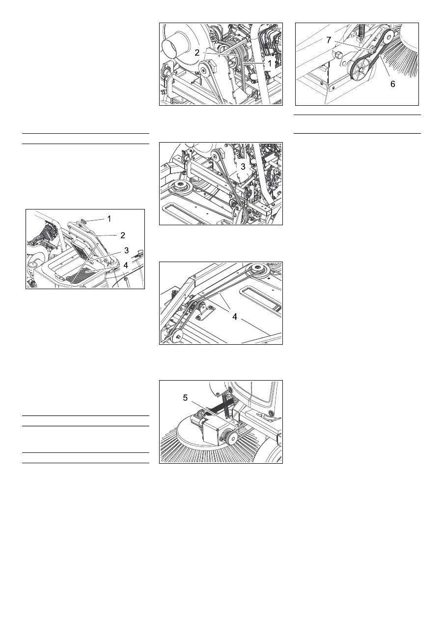
Open the device hood.
Check the V-belt axle drive (1) and V-
belt suction blower (2) for tension, wear
and damage.
V-belt axle drive (1) and V-belt suction blower (2)
Check drive belt (3) for tension, wear
and damage.
Drive belt (3)
Check drive belt (4) for tension, wear
and damage.
Drive belt (4)
Check circular belt side brush (5) for
tension, wear and damage.
Circular belt side brush (5)
Check V-belt of the roller brush drive (6)
for tension, wear and damage.
Tighten the V-belt at the screw if neces-
sary.
V-belt sweeping drive (6) and screw (7)
The drive control/electronic system is in-
stalled behind the front panel. To replace a
fuse, the front panel must be removed.
Loosen the front panel screws.
Remove front panel.
Replace defective fuses.
Note:
The assignment of fuses is indi-
cated on the inside of the panel. Only
use fuses with identical safety ratings.
Replace front panel.
Check/replace dust filter
Check suction blower
Checking drive belt
Replacing fuses of drive control/ elec-
tronic system
28 EN
Оглавление
- Inhaltsverzeichnis
- Bestimmungsgemäße Ver- wendung
- Bedien- und Funktionselemente
- Vor Inbetriebnahme
- Betrieb
- Stilllegung
- Pflege und Wartung
- Hilfe bei Störungen
- Technische Daten
- EG-Konformitätserklärung
- Contents
- Proper use
- Operating and Functional Elements
- Before Startup
- Operation
- Shutdown
- Maintenance and care
- Troubleshooting
- Technical specifications
- EC Declaration of Conformity
- Table des matières
- Utilisation conforme
- Eléments de commande et de fonction
- Avant la mise en service
- Fonctionnement
- Remisage Entretien et maintenance
- Assistance en cas de panne
- Caractéristiques techniques
- Déclaration de conformité CE
- Indice
- Uso conforme a destinazione
- Elementi di comando e di funzione
- Prima della messa in funzione
- Funzionamento
- Fermo dell'impianto Cura e manutenzione
- Guida alla risoluzione dei guasti
- Dati tecnici
- Dichiarazione di conformità CE
- Inhoudsopgave
- Reglementair gebruik
- Elementen voor de bediening en de functies
- Voor de inbedrijfstelling
- Werking
- Stillegging
- Onderhoud
- Hulp bij storingen
- Technische gegevens
- EG-conformiteitsverklaring
- Índice de contenidos
- Uso previsto
- Elementos de operación y funcionamiento
- Antes de la puesta en marcha
- Funcionamiento
- Parada
- Cuidados y mantenimiento
- Ayuda en caso de avería
- Datos técnicos
- Declaración de conformidad CE
- Índice
- Utilização conforme o fim a que se destina a máquina
- Elementos de comando e de funcionamento
- Antes de colocar em funcionamento
- Funcionamento
- Desactivação da máquina Conservação e manutenção
- Ajuda em caso de avarias
- Dados técnicos
- Declaração de conformidade CE
- Indholdsfortegnelse
- Bestemmelsesmæssig‚ anvendelse
- Betjenings- og funktionselementer
- Inden ibrugtagning
- Drift
- Afbrydning/nedlæggelsePleje og vedligeholdelse
- Hjælp ved fejl
- Tekniske data
- EU-overensstemmelseser- klæring
- Innholdsfortegnelse
- Forskriftsmessig bruk
- Betjenings- og funksjonelementer
- Før den tas i bruk
- Drift
- Sette bort
- Pleie og vedlikehold
- Feilretting
- Tekniske data
- EU-samsvarserklæring
- Innehållsförteckning
- Ändamålsenlig användning
- Manövrerings- och funktionselement
- Före ibruktagande
- Drift
- Nedstängning Skötsel och underhåll
- Åtgärder vid störningar
- Tekniska data
- Försäkran om EU-överens- stämmelse
- Sisällysluettelo
- Käyttötarkoitus
- Ohjaus- ja käyttölaitteet
- Ennen käyttöönottoa
- Käyttö
- Seisonta-aika
- Hoito ja huolto
- Häiriöapu
- Tekniset tiedot
- EU-standardinmukaisuusto- distus
- Πίνακας περιεχομένων
- Χρήση σύμφωνα με τους κανονισμούς
- Στοιχεία χειρισμού και λειτουργίας
- Πριν τη θέση σε λειτουργία
- Λειτουργία
- Διακοπή της λειτουργίας Φροντίδα και συντήρηση
- Αντιμετώπιση βλαβών
- Τεχνικά χαρακτηριστικά
- Δήλωση Συμμόρφωσης των Ε . Κ .
- İ çindekiler
- Kurallara uygun kullan ı m
- Kullan ı m ve çal ı ş ma elemanlar ı
- Cihaz ı çal ı ş t ı rmaya ba ş lamadan önce
- Çal ı ş t ı rma
- Durdurma
- Koruma ve Bak ı m
- Ar ı zalarda yard ı m
- Teknik Bilgiler
- AB uygunluk bildirisi
- Оглавление
- Использование по назначению
- Описание элементов управления и рабочих узлов
- Перед началом работы
- Эксплуатация
- Вывод из эксплуатации Уход и техническое обслуживание
- Помощь в случае неполадок
- Технические данные
- Заявление о соответствии ЕС
- Tartalomjegyzék
- Rendeltetésszer ű használat
- Kezelési- és funkciós elemek
- Üzembevétel el ő tt
- Üzem
- Leállítás
- Ápolás és karbantartás
- Segítség üzemzavar esetén
- M ű szaki adatok
- EK konformitási nyiltakozat
- Obsah
- Používání v souladu s ur č ením
- Ovládací a funk č ní prvky
- P ř ed uvedením do provozu
- Provoz
- Odstavení
- Ošet ř ování a údržba
- Pomoc p ř i poruchách
- Technické údaje
- Prohlášení o shod ě pro ES
- Vsebinsko kazalo
- Namenska uporaba
- Upravljalni in funkcijski elementi
- Pred zagonom
- Obratovanje
- Mirovanje naprave
- Nega in vzdrževanje
- Pomo č pri motnjah
- Tehni č ni podatki
- ES-izjava o skladnosti
- Spis tre ś ci
- U ż ytkowanie zgodne z przeznaczeniem
- Elementy urz ą dzenia
- Przed pierwszym uruchomieniem
- Dzia ł anie
- Wy łą czenie z eksploatacji Czyszczenie i konserwacja
- Usuwanie usterek
- Dane techniczne
- Deklaracja zgodno ś ci UE
- Cuprins
- Utilizarea corect ă
- Elemente de utilizare ş i func ţ ionale
- Înainte de punerea în func ţ iune
- Func ţ ionarea
- Scoaterea din func ţ iune
- Îngrijirea ş i între ţ inerea
- Remedierea defec ţ iunilor
- Date tehnice
- Declara ţ ie de conformitate CE
- Obsah
- Používanie výrobku v súlade s jeho ur č ením
- Ovládacie a funk č né prvky
- Pred uvedením do prevádzky
- Prevádzka
- Odstavenie
- Starostlivos ť a údržba
- Pomoc pri poruchách
- Technické údaje
- Vyhlásenie o zhode s normami EÚ
- Pregled sadržaja
- Namjensko korištenje
- Komandni i funkcijski elementi
- Prije prve uporabe
- U radu
- Stavljanje ure đ aja van pogo- na
- Njega i održavanje
- Otklanjanje smetnji
- Tehni č ki podaci
- EZ izjava o uskla đ enosti
- Pregled sadržaja
- Namensko koriš ć enje
- Komandni i funkcioni elementi
- Pre upotrebe
- Rad
- Stavljanje ure đ aja van pogona Nega i održavanje
- Otklanjanje smetnji
- Tehni č ki podaci
- Izjava o uskla đ enosti sa propisima EZ
- Съдържание
- Употреба по предназначение
- Обслужващи и функционални елементи
- Преди пускане в експлоатация
- Експлоатация
- Спиране от експлоатация Грижи и поддръжка
- Помощ при неизправности
- Технически данни
- Декларация за съответствие на ЕО
- Sisukord
- Sihipärane kasutamine
- Teenindus- ja funktsioonielemendid
- Enne seadme kasutuselevõttu
- Käitamine
- Seismapanek
- Korrashoid ja tehnohooldus
- Abi häirete korral
- Tehnilised andmed
- EÜ vastavusdeklaratsioon
- Satura r ā d ī t ā js
- Noteikumiem atbilstoša lietošana
- Vad ī bas un funkcijas elementi
- Pirms ekspluat ā cijas uzs ā kšanas
- Darb ī ba
- Iekonserv ē šana
- Kopšana un tehnisk ā apkope
- Pal ī dz ī ba darb ī bas trauc ē jumu gad ī jum ā
- Tehniskie dati
- EK Atbilst ī bas deklar ā cija
- Turinys
- Naudojimas pagal paskirt į
- Valdymo ir funkciniai elementai
- Prieš pradedant naudoti
- Naudojimas
- Laikinas prietaiso nenaudojimas
- Prieži ū ra ir aptarnavimas
- Pagalba gedim ų atveju
- Techniniai duomenys
- EB atitikties deklaracija
- Перелік
- Правильне застосування
- Елементи управління і функціональні вузли
- Перед початком роботи
- Експлуатація
- Зберігання Догляд та технічне обслуговування
- Допомога у випадку неполадок
- Технічні характеристики
- Заява при відповідність Європейського співтовариства
