Karcher ICC 2 D ECO 2SB STAGE IIIa – страница 2
Инструкция к Karcher ICC 2 D ECO 2SB STAGE IIIa

Technische Daten
ICC 2 Euro 3
Gerätedaten
Fahrgeschwindigkeit, vorwärts km/h 0-40
Fahrgeschwindigkeit, rückwärts km/h 0-6
Arbeitsgeschwindigkeit km/h 3-5
Steigfähigkeit (max.) % 25
Theoretische Flächenleistung m
2
/h 28000
Arbeitsbreite (4-Besensystem) mm 1130-2350
Arbeitsbreite (2-Besensystem) mm 1500-2000
Schutzart -- spritzwassergeschützt
Einsatzdauer bei vollem Tank h ca. 20
Motor
Hersteller -- VM-Detroit Diesel
Typ -- HR 494 HT3
Bauart -- 4-Zylinder-Euro 3-Viertakt-Dieselmotor
Gewicht kg 250
Kühlart -- Wasserkühlung
Bohrung mm 94
Hub mm 100
Hubraum cm
3
2776
Verdichtungsverhältnis -- 21,5:1
Betriebsdrehzahl 1/min 1600-2300
Leerlaufdrehzahl 1/min 750-850
Motorleistung bei 2300 1/min kW/PS 55/75
Höchstdrehmoment bei 2300 1/min Nm 225
Spezifischer Verbrauch g/kWh 260
Kraftstoff-Verbrauch l/h ca. 4
Vorglühung s ca. 8
Einspritzpumpe -- Bosch
Ölmenge l 6,4
Öldruck bei 800 1/min bar 1,2
Druckgeber für Warnleuchte bar 0,8
Ölfilter -- Filterpatrone
Ansaugluftfilter -- Außenfilterpatrone
Elektrische Anlage
Batterie V, Ah 12, 88
Anlasser kW/PS 1,4/1,8
Generator W 1000
Hydraulische Anlage
Ölmenge in der kompletten Hydraulikanlage l ca. 45
Ölmenge im Hydrauliktank l ca. 40
Ölsorten
Motor -- SAE 15W30, SAE 15W40
Hydraulik -- SHELL Tellus HV 46
Wasserpumpe -- SAE 15W40
Kehrgutbehälter
Max. Entladehöhe mm 1550
Volumen des Kehrgutbehälters l 1300
Nutzbares Gewicht kg 1300
Seitenbesen
Seitenbesen-Durchmesser (4-Besensystem) mm 600
- 20
21DE

Seitenbesen-Durchmesser (2-Besensystem) mm 925
Drehzahl (stufenlos) 1/min 30-90
Bereifung
Räder -- 6J 16 H2 5 68
Reifen -- 185/16R XCA TL 104 N
Luftdruck vorne bar 3,75
Luftdruck hinten bar 4,75
Bremse
Vorderräder -- hydraulisch
Hinterräder -- hydrostatisch
Feststellbremse -- mechanisch
Schmierfette
Für manuell abzuschmierende Schmierstellen -- NLGI-Klasse 2
Für automatische Schmieranlagen -- NLGI-Klasse 00
Umgebungsbedingungen
Temperatur °C -5 bis +40
Luftfeuchtigkeit, nicht betauend % 0 - 90
Geräuschemission
Schalldruckpegel (EN 60704-1) dB(A) 77
Garantierter Schallleistungspegel (2000/14/EC) dB(A) 107
Gerätevibrationen
Schwingungsgesamtwert (ISO 5349)
Arme, Lenkrad m/s
2
<2,5
Füße, Pedal m/s
2
<0,5
Sitzfläche m/s
2
<0,5
Maße und Gewichte
Länge x Breite x Höhe (4-Besensystem) mm 4150 x 1130 x 1904
Länge x Breite x Höhe (2-Besensystem) mm 3815 x 1250 x 1904
Leergewicht kg 2200-2290
Zulässiges Gesamtgewicht kg 3300
Inhalt Kraftstofftank, Diesel l 78
Wenderadius mm 3100
Wassertank l 300
Schallleistungspegel dB(A)
EG-Konformitätserklärung
Garantie
ICC 2
Hiermit erklären wir, dass die nachfolgend
Gemessen: 100
In jedem Land gelten die von unserer zu-
bezeichnete Maschine aufgrund ihrer Kon-
Garantiert: 102
ständigen Vertriebsgesellschaft herausge-
zipierung und Bauart sowie in der von uns
gebenen Garantiebedingungen. Etwaige
in Verkehr gebrachten Ausführung den ein-
Die Unterzeichnenden handeln im Auftrag
Störungen an Ihrem Gerät beseitigen wir
schlägigen grundlegenden Sicherheits-
und mit Vollmacht der Geschäftsführung.
innerhalb der Garantiefrist kostenlos, so-
und Gesundheitsanforderungen der EG-
fern ein Material- oder Herstellungsfehler
Richtlinien entspricht. Bei einer nicht mit
die Ursache sein sollte. Im Garantiefall
uns abgestimmten Änderung der Maschine
wenden Sie sich bitte mit Kaufbeleg an Ih-
verliert diese Erklärung ihre Gültigkeit.
CEO
Head of Approbation
ren Händler oder die nächste autorisierte
Kundendienststelle.
Produkt: Straßenkehrmaschine
Dokumentationsbevollmächtigter:
Typ: 1.183-xxx
S. Reiser
Einschlägige EG-Richtlinien
Alfred Kärcher GmbH & Co. KG
2006/42/EG (+2009/127/EG)
Alfred-Kärcher-Str. 28 - 40
2004/108/EG
71364 Winnenden (Germany)
2000/14/EG
Tel.: +49 7195 14-0
Angewandte harmonisierte Normen
Fax: +49 7195 14-2212
EN 13019
CISPR 12
Angewandtes Konformitätsbewer-
tungsverfahren
2000/14/EG: Anhang V
22 DE
- 21
Leaf suction (accessory)
– It is strictly prohibited to take co-pas-
Please read and comply with
EN
. . .9
sengers.
these instructions prior to the
Transport . . . . . . . . . . . .
EN
. .10
initial operation of your appliance. Retain
– The appliance may only be started after
Towing . . . . . . . . . . . . . .
EN
. .10
these operating instructions for future refer-
the operator has occupied the driver's
Shutdown. . . . . . . . . . . . . . . EN . .10
ence or for subsequent possessors.
seat.
Maintenance and care . . . . . EN . .10
Before first start-up it is definitely neces-
Please remove the ignition key, when
General notes . . . . . . . .
EN
. .10
sary to read the safety indications Nr.
not in use, to avoid unauthorised use of
5.956-250!
Cleaning. . . . . . . . . . . . .
EN
. .10
the appliance.
Maintenance intervals . .
EN
. .11
Never leave the machine unattended
Contents
Maintenance Works . . . .
so long as the engine is running. The
EN
. .12
operator may leave the appliance only
Accessories . . . . . . . . . . . . . EN . .18
Safety instructions . . . . . . . EN . . 1
when the engine has come to a stand-
Troubleshooting . . . . . . . . . . EN . .19
General notes . . . . . . . .
. . 1
still, the appliance has been protected
EN
Technical specifications . . . . EN . .20
against accidental movement, if neces-
Symbols on the machine
EN
. . 2
EC Declaration of Conformity EN . .21
sary, by applying the immobilization
Symbols in the operating in-
Warranty . . . . . . . . . . . . . . . EN . .21
brake and the ignition key has been re-
structions. . . . . . . . . . . . EN
. . 2
moved.
Function . . . . . . . . . . . . . . . EN . . 2
Safety instructions
Proper use . . . . . . . . . . . . . EN . . 2
Appliances with combustion engine
Suitable surfaces. . . . . .
EN
. . 2
Danger
General notes
Environmental protection . . EN . . 2
Risk of injury!
Your sales outlet should be informed about
Operating and Functional Ele-
– Do not close the exhaust.
any transit damage noted when unpacking
ments . . . . . . . . . . . . . . . . . EN . . 3
– Do not bend over the exhaust or touch
the product.
4-brush system . . . . . . .
EN
. . 4
it (risk of burns).
Please read the operating instructions
2-brush system . . . . . . .
EN
. . 4
– Do not touch the drive motor (risk of
for your machine before using it, and
burns).
Operator console. . . . . .
EN
. . 4
pay particular attention to the following
– Exhaust gases are poisonous and haz-
Console. . . . . . . . . . . . .
EN
. . 4
safety instructions.
ardous to health, do not inhale them.
Switch strip . . . . . . . . . .
. . 4
– Warning and information plates on the
EN
– The engine requires approx. 3-4 sec-
machine provide important directions
Operation . . . . . . . . . . . . . . EN . . 5
onds to come to a standstill once it has
for safe operation.
Warning system . . . . . .
EN
. . 5
been switched off. During this time, stay
– In addition to the information contained
Multifunction display . . .
EN
. . 5
well clear of the working area.
in the operating instructions, all statuto-
Wiper. . . . . . . . . . . . . . .
EN
. . 5
ry safety and accident prevention regu-
Turbine casing
Windscreen washer system
EN
. . 5
lations must be observed.
Adjust rear mirror . . . . .
EN
. . 5
Drive mode
Adjust exterior mirror. . .
EN
. . 5
Danger
Heating for exterior mirror
Risk of injury!
(attachment) . . . . . . . . . EN
. . 5
Danger of tipping if gradient is too high.
Working light . . . . . . . . .
EN
. . 5
– The gradient in the direction of travel
Overall lamp . . . . . . . . .
EN
. . 5
should not exceed 25%.
Combination switch. . . .
EN
. . 5
Danger of tipping when driving round
Driving direction lever . .
EN
. . 5
bends at high speed.
– Drive slowly when cornering.
Parking brake . . . . . . . .
EN
. . 6
Danger of tipping on unstable ground.
Danger
Adjusting driver's seat . .
EN
. . 6
– Only use the machine on sound surfac-
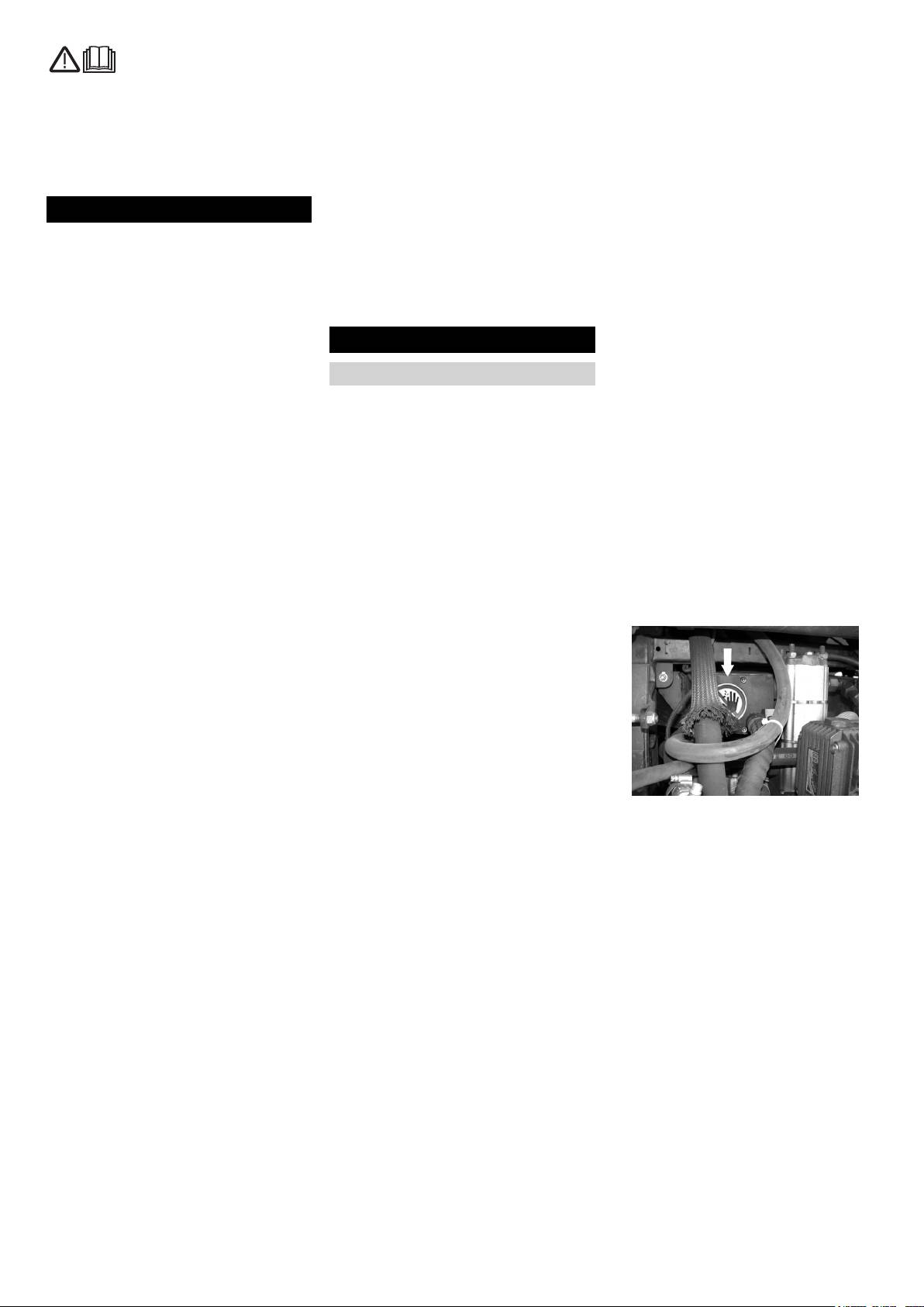
Risk of injury if the diesel motor is running!
Comfortable seat (accesso-
es.
ry) . . . . . . . . . . . . . . . . . EN
. . 6
– Never open the side panel of the turbine
Danger of tipping with excessive sideways
casing (below the turbine).
12V connection . . . . . . .
EN
. . 6
tilt.
– Do not put your hands inside the turbine
Blower . . . . . . . . . . . . . .
EN
. . 6
– The gradient perpendicular to the direc-
casing.
Air-conditioner (accessory)
EN
. . 6
tion of travel should not exceed 10%.
– Do not spray water into the turbine cas-
Fresh air circulation. . . .
EN
. . 6
– It is important to follow all safety instruc-
ing.
Heating . . . . . . . . . . . . .
EN
. . 6
tions, rules and regulations applicable
Accessories and Spare Parts
Before Startup. . . . . . . . . . . EN . . 6
for driving motor vehicles.
– Only use accessories and spare parts
Unloading . . . . . . . . . . .
– The operator must use the appliance
EN
. . 6
which have been approved by the man-
properly. He must consider the local
Start up . . . . . . . . . . . . . . . . EN . . 6
ufacturer. The exclusive use of original
conditions and must pay attention to
General notes . . . . . . . .
EN
. . 6
accessories and original spare parts
third parties, in particular children, when
ensures that the appliance can be oper-
Refuelling . . . . . . . . . . .
EN
. . 6
working with the appliance.
ated safely and troublefree.
Inspection and maintenance
– The appliance may only be used by per-
work. . . . . . . . . . . . . . . . EN
. . 6
– At the end of the operating instructions
sons who have been instructed in han-
you will find a selected list of spare
Operation . . . . . . . . . . . . . . EN . . 6
dling the appliance or have proven
parts that are often required.
Starting the machine . . .
EN
. . 6
qualification and expertise in operating
– For additional information about spare
Drive the machine . . . . .
EN
. . 6
the appliance or have been explicitly
parts, please go to the Service section
Sweeping mode . . . . . .
EN
. . 7
assigned the task of handling the appli-
at www.kaercher.com.
ance.
Emptying waste container
EN
. . 9
– The appliance must not be operated by
Emptying the waste contain-
er manually . . . . . . . . . . EN
. . 9
children, young persons or persons
who have not been instructed accord-
Turn off the appliance . .
EN
. . 9
ingly.
- 1
23EN
Symbols on the machine
Proper use
Environmental protection
Use this appliance only as directed in these
Risk of burns on ac-
The packaging material can be
operating instructions.
count of hot surfaces!
recycled. Please do not throw
The machine with working equipment
Allow the exhaust to
the packaging material into
must be checked to ensure that it is in
cool down sufficiently
household waste; please send
proper working order and is operating
before starting work on
it for recycling.
safely prior to use. Otherwise, the appli-
the machine.
ance must not be used.
Old appliances contain valua-
Symbols in the operating instruc-
– This sweeper has been designed to
ble materials that can be recy-
cled; these should be sent for
tions
sweep dirt and debris from outdoor sur-
faces.
recycling. Batteries, oil, and
Danger
– The appliance should not be used in
similar substances must not en-
indicates an immediate threat of danger.
closed rooms.
ter the environment. Please dis-
Failure to observe the instruction may re-
pose of your old appliances
– The machine is not suitable for vacuum-
sult in death or serious injuries.
using appropriate collection
ing dust which endangers health.
systems.
몇 Warning
– The machine may not be modified.
indicates a possibly dangerous situation.
– Never vacuum up explosive liquids,
Failure to observe the instruction may re-
combustible gases or undiluted acids
sult in light injuries or damage to property.
and solvents. This includes petrol, paint
Note
thinner or heating oil which can gener-
ate explosive fumes or mixtures upon
indicates useful tips and important informa-
contact with the suction air. Acetone,
tion.
undiluted acids and solvents must also
be avoided as they can harm the mate-
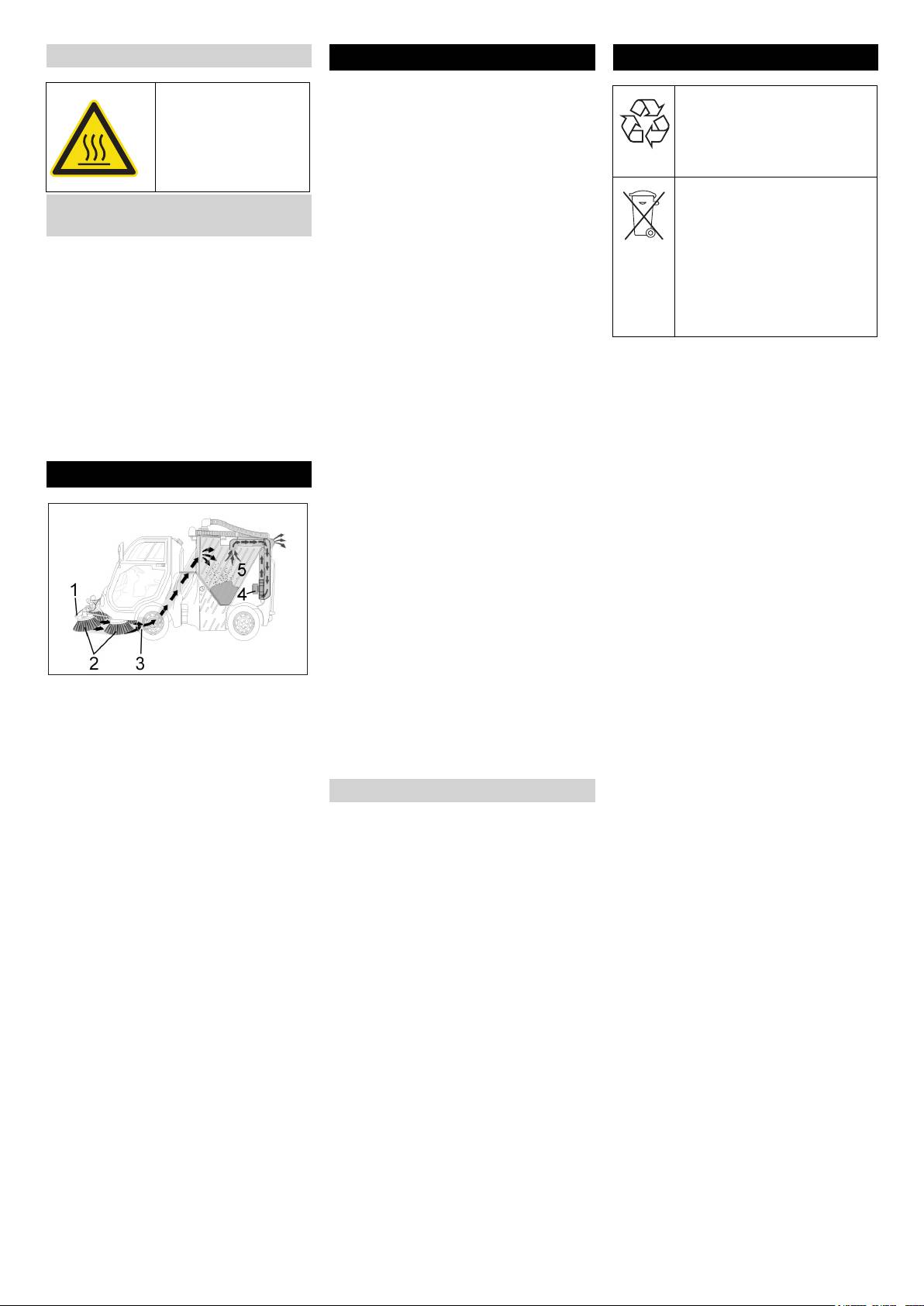
Function
rials on the machine.
– Do not sweep/vacuum up any burning
or glowing objects.
– The machine is only suitable for use on
the types of surfaces specified in the
operating instructions.
– The machine may only be operated on
the surfaces approved by the company
or its authorised representatives.
– The machine may not be used or stored
in hazardous areas. It is not allowed to
use the appliance in hazardous loca-
– The generated dust is bound through
tions.
water (1) that is sprayed.
– The following applies in general: Keep
– The side brushes (2) transport the dust
highly-flammable substances away
to the front of the suction opening (3).
from the appliance (danger of explo-
– The suction turbine (4) sucks in the
sion/fire).
waste and transports it to the waste
container (5).
Suitable surfaces
– Asphalt
– Industrial floor
– Screed
– Concrete
– Paving stones
24 EN
- 2
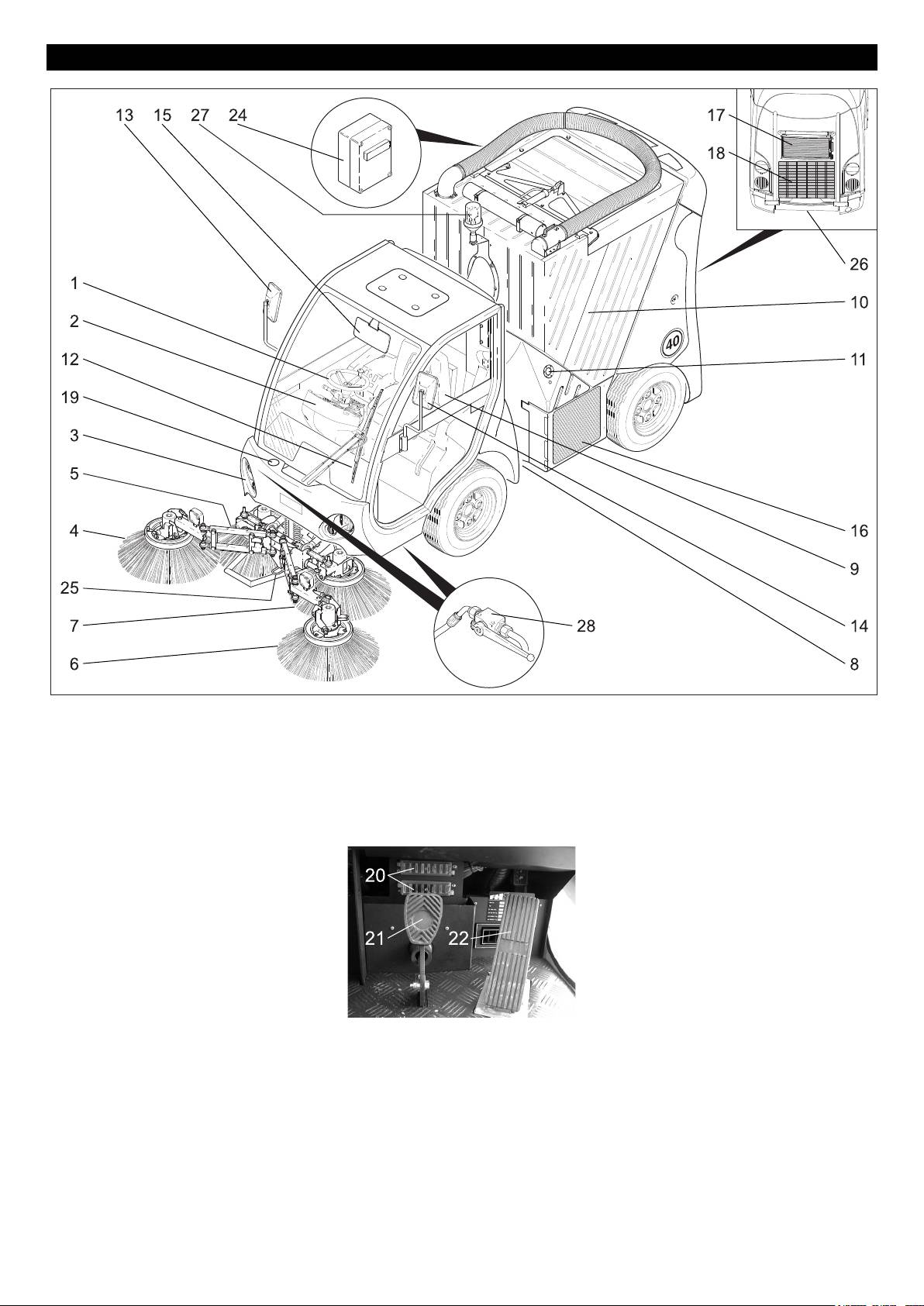
Operating and Functional Elements
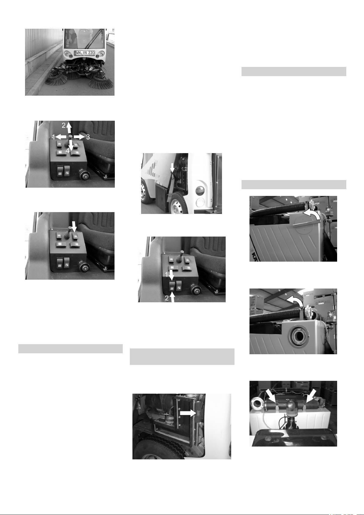
Figure 1
1 Steering wheel
24 Fuse box motor room
2 Operator console
25 Towing eye, front
3 Lights
26 Towing eye, rear
4 Right side bush, front
27 Overall lamp
(only 4 brush system)
28 Stop for side brush elevation
5 Right side bush, rear
(only 2-brush system)
(only 4 brush system)
6 Left side bush, front
(only 4 brush system)
7 Left side bush, rear
(only 4 brush system)
8 Bulk waste flap
9 Driver seat
10 Waste container
11 Fuel tank
12 Wiper
Figure 2
13 Right exterior mirror
14 Left exterior mirror
15 Rear-view mirror
16 Water cooler
17 Oil cooler
18 Cooler for air-conditioner (accessory)
19 Container for wiper water
20 Fuse box driver cabin
21 Brake pedal
22 Drive pedal
23 Pedal for raising/lowering bulk waste
flap
- 3
25EN
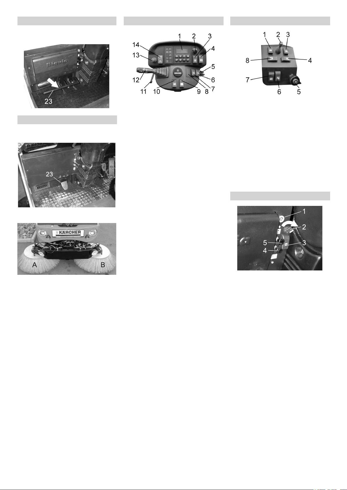
4-brush system
Operator console Console
– Pedal for raising/lowering bulk waste
flap
Figure 6
Figure 7
1 Display
1 Raise/lower side-brushes
Figure 3
2 Setting the speed of the side-brushes
Hydraulic side-brush release (attach-
3 Working hydraulics
ment)
2-brush system
1. Step = switch on the working hydrau-
2 Move in/out the joystick of the side-
–
Pedal for raising/lowering bulk waste
lics
brush
flap
2. step = switch on the suction turbine
3 Lock side-brush
and the side-brushes
4 Inclination of side-brush, left
4 raising the suction mouth
(only 4 brush system)
5 Ignition lock
5 Setting the motor rpm
6 Windscreen washer system
6 Turn on/off the spray water
7 Wiper
7 Raise/lower waste container
8 Heating for exterior mirror (attachment)
8 Inclination of side-brush, right
9 Overall lamp
(only 4 brush system)
10 Switch for working lamp
Switch strip
11 Adjusting the steering column
12 Combination switch
Figure 4
13 Driving direction lever
14 Warning system
Figure 8
1 12V connection
Figure 5
2 Blower
A Right side brush
3 Switch on/off air-conditioner (accesso-
B Left side brush
ry)
4 Fresh air circulation
5 Heating
26 EN
- 4
Motor on
Operation
Combination switch
Display row 2
Warning system
Battery voltage
Turning on/off the warning system:
Press the switch for warning system.
Motor off
Ignition on
Multifunction display
Display row 1
Vehicle voltage
Motor on
Display row 1
Service interval SIA
1 Parking light
2 Dipped beam
Display row 2
3 Flashing
Filter replacement > 320 h
4 Full beam
Indicator lamps
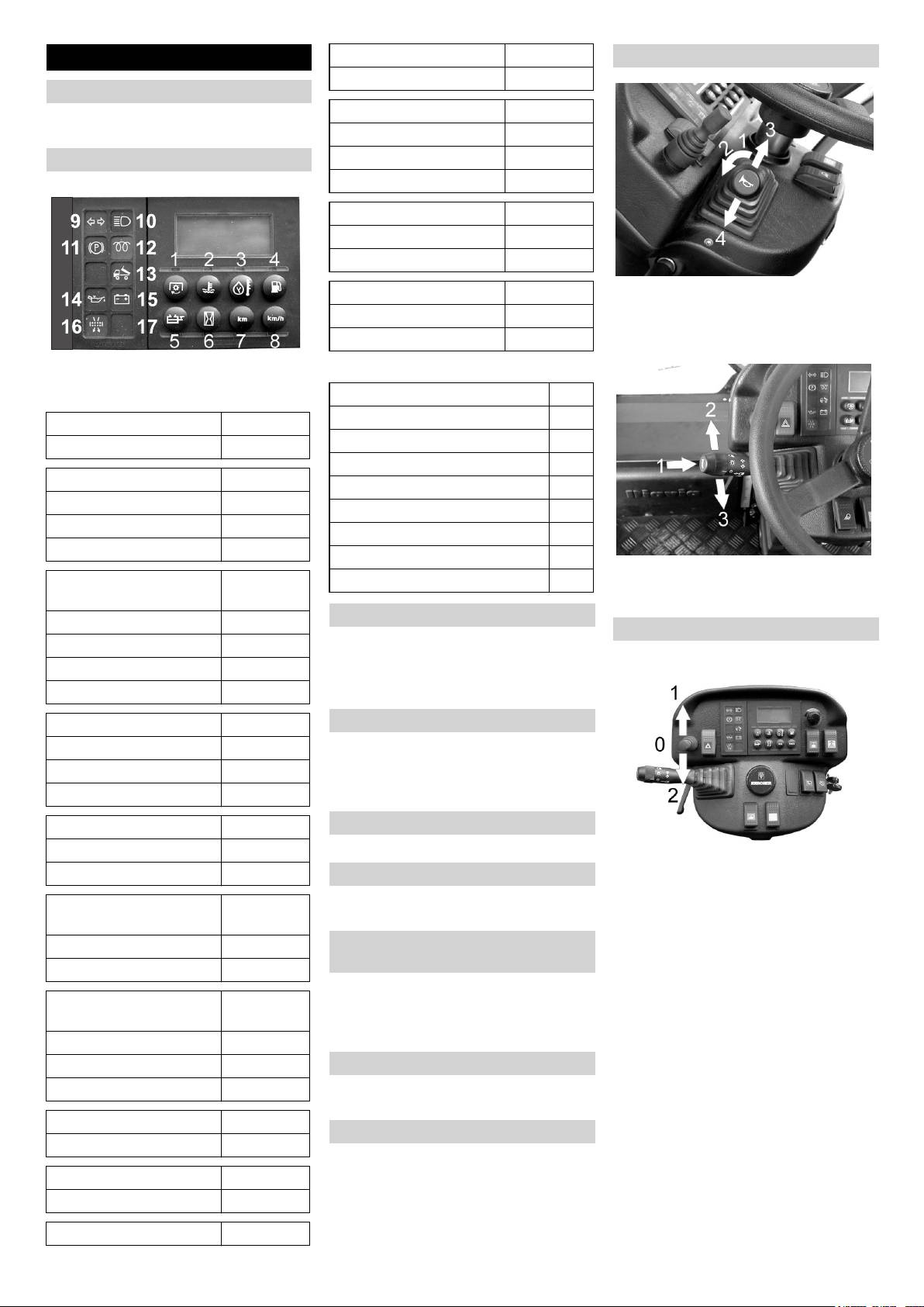
Figure 9
Keys
Blinker left/right (9)
Full beam (10)
Motor rpm (1)
Activate parking brake (11)
Display row 1
Preglowing (hold for 3 seconds) (12)
Cool water temperature (2)
Waste container is raised (13)
Display row 1
Motor oil pressure is too low (14)
Warning tone 1 (- - - -) > 108 °C
Battery charge is low (15)
Warning tone 2 (____) > 115 °C
Air filter is dirty (16)
1 Horn
Temperature of hydraulic
(3)
Spray water pump is switched on (17)
2 Right indicator
oil
3 Left indicator
Wiper
Display row 1
Driving direction lever
Warning tone 1 (- - - -) > 75 °C
Turn on/off the wiper:
Press the switch for wiper.
Warning tone 2 (____) > 80 °C
– 1. stage = interval
Acknowledgement (3)
– 2. stage = constant
Fuel tank level (4)
Windscreen washer system
Display row 1
Turn on/off the windscreen washer system.
Press the switch for windscreen washer
Warning tone 1 (- - - -) < 15 l
system.
Acknowledgement (4)
Spray water for the front wiper is activated.
Water tank level (5)
Adjust rear mirror
Display row 2
Adjust rear mirror manually.
Call off (5)
0 = Neutral
Adjust exterior mirror
1 = Forward drive
Adjust the left and right exterior mirror
Operating hours meter for
(6)
2 = Reverse
manually.
motor
Display row 2
Heating for exterior mirror (attach-
ment)
Call off (6)
Turn on/off the heating for the exterior mir-
Operating hours meter for
(6)
ror.
turbine
Press the switch for heating for exterior
Motor off
mirror.
Ignition on
Working light
Display row 2
Turning on/off the working light:
Press the switch for the working light.
Driving route (7)
Overall lamp
Display row 2
Turning on/off the overall lamp:
Speed (8)
Press the switch for the overall lamp.
Display row 2
Time (1)-(8)
- 5
27EN
Parking brake
12V connection
Fuelling using a can
– Estimate the fuel requirement in order
Insert the consumer load at 12V-con-
Lock parking brake
to avoid overflows.
nection.
Fuelling using the fuelling gun
(see switch strip)
– Insert the fuelling gun as deep as possi-
Blower
ble into the fuel nozzle. Do not add any
more fuel once the fuelling gun stops
Switch on/off the blower.
according to the settings.
(see switch strip)
– for heating: level 2
Inspection and maintenance work
– for air-conditioner: level 3
Check engine oil level. *
Air-conditioner (accessory)
Check water cooler and maintain it. *
Check tyre pressure. *
Turn on/off the air-conditioner.
Check fill level of fuel tank. *
(see switch strip)
Pull up the handle.
Adjust driver's seat.
Release parking brake
Fresh air circulation
Check suction channel. *
Press the locking button and release
Activate the slide.
Check setting of suction opening. *
the handle.
(see switch strip)
Check lights and ensure that they are
functioning properly. *
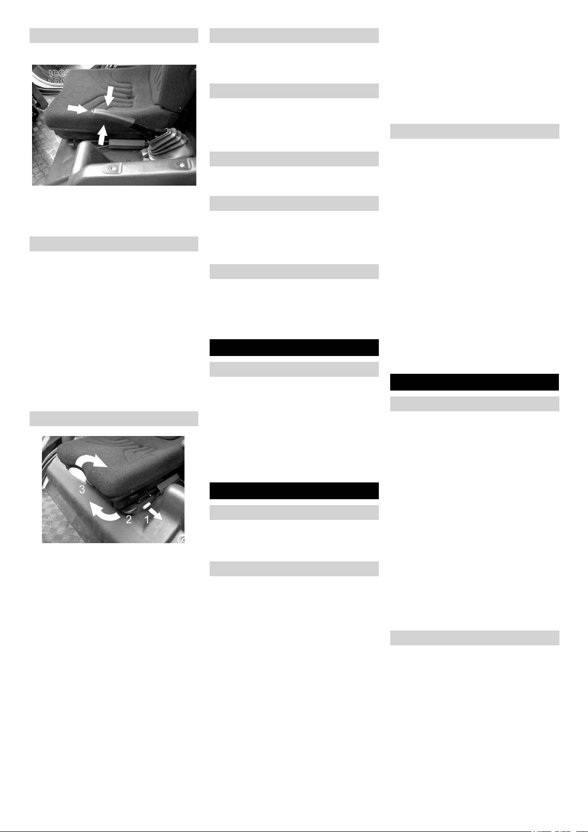
Adjusting driver's seat
– Slide is pushed in = fresh air
– Slide is pulled out = air circulation
Check signaling and warning systems
Adjusting the seat position
for proper functioning. *
Heating
Pull upwards the lever located under
Fill the water reservoir. *
the seat.
Activate the slide.
Check side brush. *
Slide seat, release lever and lock in
(see switch strip)
Empty waste container.
place.
– Slide is pushed in = cold
* For description, see section on Care and
Check that the seat is properly locked in
– Slide is pulled out = warm
maintenance.
position by attempting to move it back-
몇 Warning
wards and forwards.
Before Startup
Rectify any defect you may find immediate-
Adjusting the seat springs
ly or bring the vehicle to a halt.
Turn the hand-wheel at the rear of the
Unloading
seat.
Operation
Note
– In clock-wise direction: Spring harder
The appliance is fitted with tension belts for
– Anti-clockwise direction: Spring softer
Starting the machine
safe transport.
Comfortable seat (accessory)
To unload the machine, proceed as follows:
Sit on the driver's seat.
Remove tension belts.
Do NOT press the accelerator pedal.
Release parking brake.
Lock parking brake.
Drive down the appliance from the
Switch off the working hydraulic.
transport vehicle.
Set the drive direction indicator to posi-
tion (0) (neutral).
Start up
Pre-heat
Turn the ignition key to position "I".
General notes
Pre-heat lamp glows.
Park the sweeper on an even surface.
Start the engine
Remove ignition key.
When the pre-heating lamp goes off,
Adjusting the seat position
Lock parking brake.
turn the ignition key to position "II".
Press the lever (1).
If the machine starts, release the igni-
Refuelling
Slide seat, release lever and lock in
tion key.
place.
Danger
Note
Check that the seat is properly locked in
Risk of explosion!
Never operate the starter motor for longer
position by attempting to move it back-
– Only use the fuels specified in the Op-
than 10 seconds. Wait at least 10 seconds
wards and forwards.
erations Manual.
before operating the starter motor again.
– Do not refuel the machine in enclosed
Adjusting the seat springs
Drive the machine
spaces.
Tilt the lever (2) until the scales show
– Smoking and naked flames are strictly
your body weight.
Drive forward
prohibited.
– Set the body weight between 50-130
Press the brake pedal.
– Ensure that no fuel reaches the hot
kg.
Set the drive direction indicator to posi-
open surfaces.
– If you tilt until the end, the setting is
tion (1) (drive forwardl).
Switch off engine.
done for 50 kg.
Release parking brake.
Open fuel filler cap.
Press accelerator pedal down slowly.
Adjust seat position
Fill in diesel.
Tilt the handle (3).
Reverse drive
Fill in the tank up to a level 1 cm below
Adjust the seat.
Danger
the lower edge of the filling nozzle be-
Risk of injury! While reversing, ensure that
cause the fuel expands on heating.
there is nobody in the way, ask them to
Wipe off any spilt fuel and close fuel fill-
move if somebody is around.
er cap.
Press the brake pedal.
28 EN
- 6
Set the drive direction indicator to posi-
Switching on the working hydraulics
tion (2) (reverse drive).
Turn on the working hydraulics (1st lev-
Release parking brake.
el).
Press accelerator pedal down slowly.
(see operating panel).
Note
Switch on the suction turbine and the
Driving method
side-brushes (2nd step).
– A warning tone is sounded while revers-
Note
ing.
Only driving is possible if the working hy-
– The accelerator pedal can be used to
draulics is switched off.
vary the driving speed infinitely.
Adjusting the side-brush speed
– Avoid pressing the pedal suddenly as
Set the side-brush speed on the speed
this may damage the hydraulic system.
regulator.
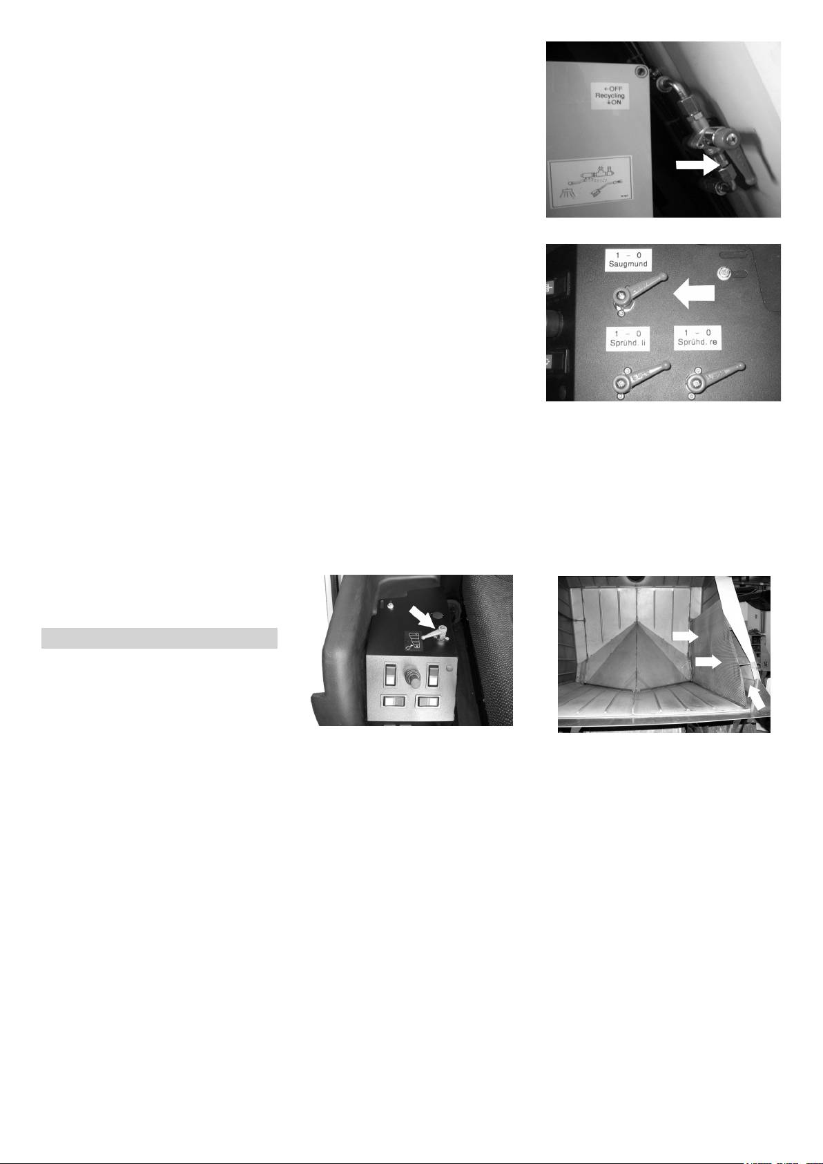
Set the lever for recycling to ON.
– In the event of power loss on inclined
(see operating panel).
surfaces, slightly reduce the pressure
– In clock-wise direction: Side-brush
on the accelerator pedal.
speed increases
– Change the driving direction only after
– Anti-clockwise direction: Side-brush
the vehicle has come to a halt.
speed decreases
Brakes
Turn on/off the spray water
Release the accelerator pedal, the ma-
Press spray water button.
chine brakes automatically and stops.
(see console ).
Note
Spray water for side-brushes and suction
The braking effect can be supported by
opening gets activated.
pressing the foot-brake.
Regulate additional supply of fresh wa-
Note
Driving over obstacles
ter to the suction opening using the le-
The function of the spray-water pump is
몇 Warning
ver for suction opening.
displayed on a yellow indicator lamp, see
Switch on the suction turbine; start
Raise the side-brushes and the suction
multi-functional display.
cleaning work.
opening before overtaking hurdles.
If the tank is empty, the yellow indicator
Hurdles up to 150 mm in height:
After finishing operations, switch off the
lamp goes off.
Bypass the hurdle slowly and carefully
suction turbine approx. 30 seconds af-
Switch-off spray water.
at an angle of 45°.
ter the suction opening has got raised.
Fill the water reservoir.
This will prevent water from leaking
Hurdles more than 150 mm in height:
Regulate the water flow to the side-
when the appliance has been switched
Only drive over these obstacles using a
brushes.
off.
suitable ramp.
몇 Warning
Risk of damage! Ensure that the vehicle
does not get stuck up.
Sweeping mode
Danger
Risk of injury! If the bulk waste flap is open,
stones or gravel may be flung forwards by
the roller brush. Make sure that this does
not endanger persons, animals or objects.
Adjust the water flow to the side-brush-
몇 Warning
es using the regulation valve.
Every time you empty the waste con-
Do not sweep up packing strips, wire or
– In clock-wise direction: Water flow in-
tainer, rinse the sieve in the waste con-
similar objects as this may choke up the
creases
tainer using the water hose and clean
suction canal.
– Anti-clockwise direction: Water flow de-
the space behind the sieve.
몇 Warning
creases
Set the lever for recycling to OFF while
To avoid damaging the floor, do not contin-
operating without water circulation.
Note
ue to operate the sweeping machine in the
There is an accessory with 2 regulation
Operating without water circulation sys-
same position.
valves for separately controlling the water
tem
Note
flow to both the sides.
When the appliance is switched off,
To achieve an optimum cleaning result, the
make sure the lever for recycling is set
Water circulation system
driving speed should be adjusted to take
to OFF because otherwise the hoses
The applicance is fitted with a water circu-
specific situations into account.
leading to the suction opening will get
lation system for increasing the duration of
Note
blocked.
usage (fresh water reservoir). In the water
circulation system, the water from the
The sieve and the space behind the
During operation, the waste container
sieve must be cleaned every time you
should be emptied at regular intervals.
waste container is guided to the suction
opening and thus circulated. Further, it is
empty the waste container even if you
Setting the motor rpm
also possible to add fresh water.
are operating the appliance without wa-
Set the idle running for the motor rpm
Fill the waste container with water up to
ter circulation.
setting to 1600-1800 1/min.
the end of the front slant. To suck in
Raise/lower side-brushes
(see console ).
leaves, fill lesser quantity of water in the
4-brush system:
Note
waste container.
Press the toggle switch downward. The
The motor rpm can be called via the multi-
side-brushes will be lowered.
functional display.
(see console ).
- 7
29EN
Press the toggle switch upward. Side
Move in/out the side-brush
brushes lift up.
2-brush system:
Press the toggle switch downward. The
side-brushes will be lowered.
(see console ).
Press the toggle switch upward. Side
brushes lift up.
Hydraulic side-brush relief (attachment)
– The hydraulic side-brush relief reduces
the contact pressure of the brush on the
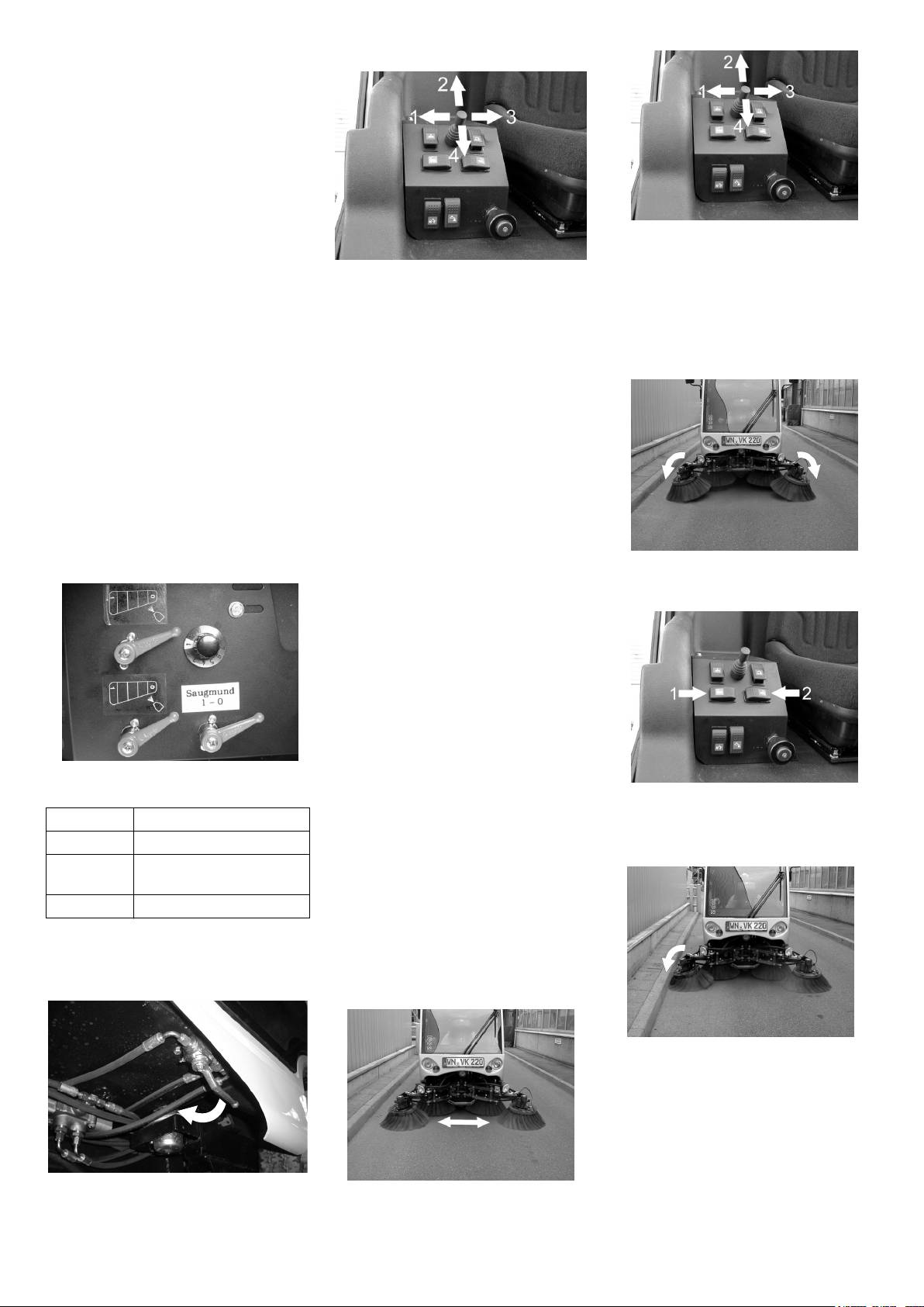
Drive out the side-brushes (2).
track.
Drive in the side-brushes (4).
– The floor is protected against friction
Note
Move joystick to position (2). Side-
and wear if the brushes are relieved
brushes are driven out.
The sweeping width should be adjusted ac-
and this also increases the life of the
Move joystick to position (4). Side-
cording to how dirty the plane surface is so
brushes.
brushes are drawn in.
that the waste can be sucked in completely.
– The relief can be adjusted in infinitely
Note
Inclination of the front side-brushes (on-
variable steps depending on the track
ly 4-brush system)
surface and the dirt that appears.
Only 2-brush system: The side-brushes
can only be driven out when they are rotat-
Raise/lower side-brushes:
ing.
Press the toggle switch downward. The
side-brushes are lowered; the relief is
Sweeping in larger objects
deactivated.
Note
(see console ).
To sweep in larger objects such as bever-
Toggle switch in central position. The
age cans or larger quantities of leaves, it is
side-brushes are lowered; the relief is
necessary to briefly raise the bulk waste
activated.
flap.
Press the toggle switch upward. Side
Raising bulk waste flap:
brushes lift up.
Press the pedal for the bulk waste flap
The inclination of the front side-brushes
Setting the hydraulic side-brush relief:
forwards and keep pressed down.
can be adjusted according to the geometry
To lower it, take foot off pedal.
of the driving path.
Note
An optimum cleaning result can only be
achieved if the bulk waste flap has been
lowered completely.
Sweeping dry floors
To avoid deposits in the suction channel
and durst formation, the water supply to the
brush nozzles must be on.
Switch on the spray water.
(see console ).
Setting the relief of the brushes at the
speed regulator.
Sweeping damp or wet floors
Tilt the right side-brushes (1).
Switch off the water supply to the brush
Tilt the left side-brushes (2).
Position Relief on the brushes
nozzles if there is practically no dust forma-
Sweeping along the limitations of the
1 minimum
tion.
driving path (only 4-brush system)
Switch-off spray water.
5-8 medium (recommended
setting)
(see console ).
Note
11 maximum
To achieve an optimum cleaning result, the
Stop side-brush lift up (only 2-brush
driving speed or rahter the sweeping width
system)
should be adjusted to take specific situa-
The side-brushes can individually be
tions into account.
stopped in a raised position.
Sweeping plane surfaces
Tilt the right side-brushes if required.
Close the ball tap when the side-brush-
The front side-brushes can be driven in or
es are lifted up.
out depending on how dirty the plane sur-
face is.
30 EN
- 8
that no persons or animals are within its
Sweeping at narrow places
몇 Warning
swivelling range.
Manually lift the lid of the waste container
Danger
before starting the pumping operations.
Danger of crushing. Never reach into the
This will help in avoiding damage to the
rod assembly for the drainage mechanism.
rear panel.
Raise the waste container through
Note
pumping.
Always raise the waste container complete-
ly until its end position.
Turn off the appliance
Switch off the spray water for side-
Switch off the spray water for side-
brushes and suction opening.
brushes and suction opening.
Stop the machine.
Stop the machine.
To sweep in edge area on right-hand side:
Lock parking brake.
Lock parking brake.
Drive in the left side-brush and drive out
Set the drive direction indicator to posi-
Set the drive direction indicator to posi-
the right side-brush (1).
tion (0) (neutral).
tion (0) (neutral).
Drive in the side-brushes.
Drive in the side-brushes.
The side-brushes lift up.
The side-brushes lift up.
Switch off the suction turbine and the
Switch off the suction turbine and the
side-brushes (2nd step).
side-brushes (2nd step).
Turn off the working hydraulics (1st lev-
el).
Set the dry run speed.
Turn ignition key to "0" and remove it.
Leaf suction (accessory)
To sweep in edge area on left-hand side:
Drive in the right side-brush and drive
out the left side-brush (3).
Open the side-flaps.
Drain off water on both sides.
Open the screw cap.
Hang in the special tool (accessory)
and turn in anti-clockwise direction.
– The left side-brushes can be locked to
sweep narrow passages or foot-paths.
– The right side-brushes can still be
moved using the joystick in position (1)
Raise waste container (1).
and (3).
Empty waste container.
– If you move the joystick to position (2)
Lower waste container (2).
and (4), both the side-brushes in or out.
Note
– At narrow bends, turn in the external
There is a warning sound signal when the
brushes.
waste container is lowered.
Emptying waste container
Emptying the waste container man-
Danger
Loosen the fasteners of the suction
ually
hose.
Risk of injury! While reversing, ensure that
Lock parking brake.
Connect the hose to the nozzle.
there is nobody in the way, ask them to
Open the side-flaps.
move if somebody is around.
Drain off water on both sides.
Danger
Danger of tipping. Place the machine on an
even surface during emptying.
Danger
Danger of tipping. Maintain the required
safety distance while emptying on dumps
or ramps.
Danger
Risk of injury! Switch off the suction turbine
Loosen the fasteners of the suction
before emptying the waste container.
nozzle
Danger
Remove the operating lever for the
Risk of injury! When emptying the waste
pump.
container, care should be taken to ensure
Insert the operating lever on the pump
lever.
- 9
31EN
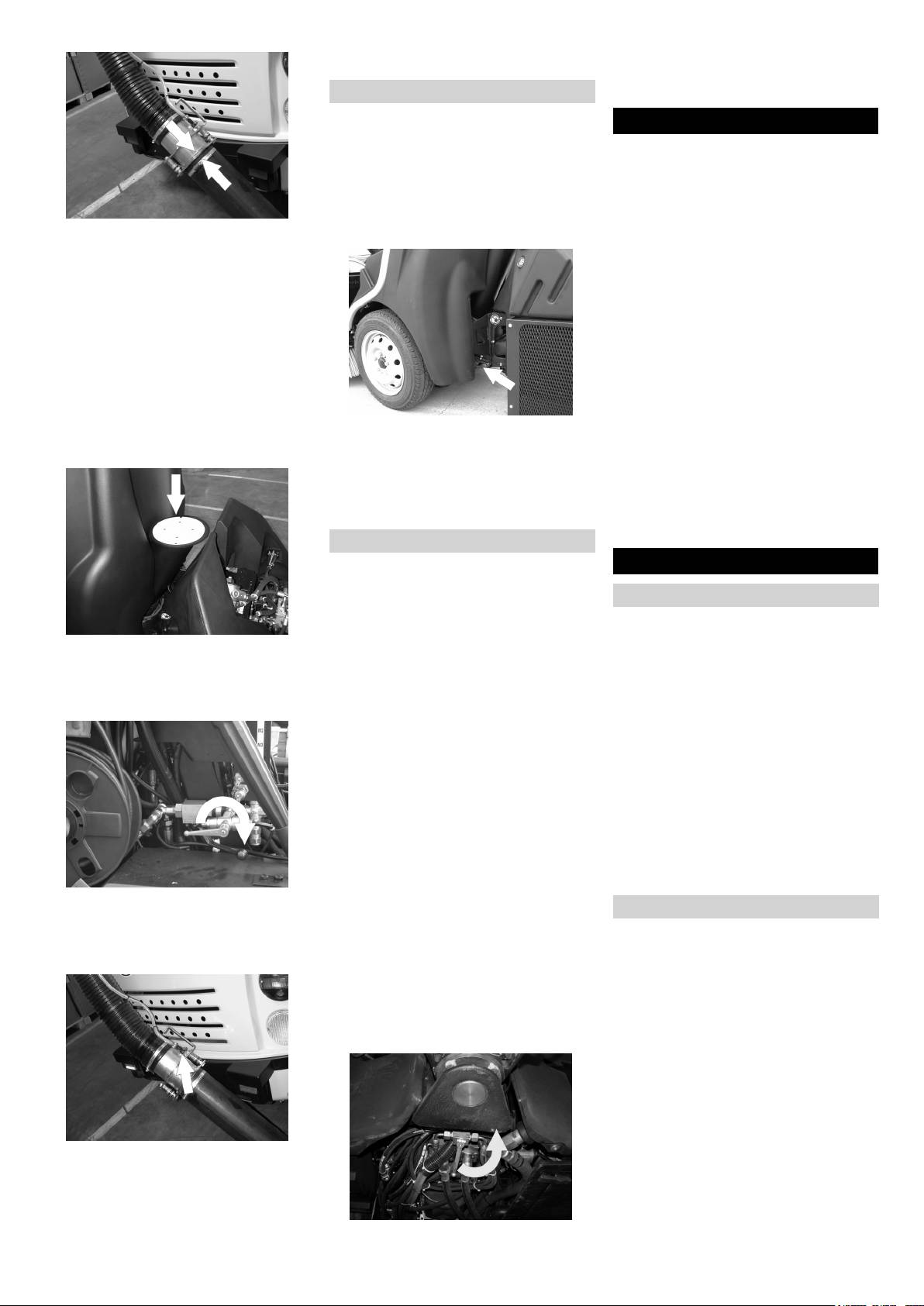
Shift the water supply from leaf suction
Open the bypass valve using the hand
to sweeping operations.
gear from the tool box or a flat spanner
(SW 9).
Transport
몇 Warning
Shutdown
The appliance must be secured against
If the sweeper is going to be out of service
slippage during transport.
for a longer time period, observe the follow-
Turn ignition key to "0" and remove it.
ing points:
Lock parking brake.
Park the sweeper on an even surface.
Secure the wheels of the machine with
Raise the side-brushes to prevent the
Connect the suction nozzle to the suc-
wheel chocks.
bristles from being damaged.
tion hose.
Turn ignition key to "0" and remove it.
Set the dry run speed to approx. 1800
Secure sweeper to prevent it rolling
1/min.
away, lock parking brake.
Note
Tank up the fuel tank fully.
The motor rpm can be called via the multi-
Change the engine oil and the oil filter.
functional display.
Drain off the spray water if frost is ex-
Turn on the working hydraulics (1st lev-
pected and check whether is adequate
el).
anti-frosting agent in the cooling water.
Press switch for raising the suction
Empty the water tank and the pipe sys-
mouth.
tem.
– 1. step = raise the suction opening
Secure the appliance with tension
Disconnect battery.
– 2. step = switch on/off the side-brushes
straps at the fastening eyes on the left
Charge battery approx. every 2 months.
and the right.
Clean the inside and outside of the
몇 Warning
sweeper.
Risk of damage! The front towing eye
Park the machine in a safe and dry
should not be used to fasten the appliance.
place.
Towing
Maintenance and care
Danger
When carrying out rescue work on public
General notes
highways, wear warning clothing when
working close to passing traffic.
First switch off the appliance and re-
move the ignition key before performing
Raise waste container.
Danger
any cleaning or maintenance tasks on
Cover the suction pipe with a plate
The hydro-static drive of the sweeper per-
the appliance, replacing parts or switch-
when sucking in leaves.
mits towing out of the danger area only for
ing over to another function.
Lower waste container.
a few metres at walking speed. Do not
Pull out the battery plug or clamp the
move the sweeper at a speed higher than
battery while working on the electrical
walking speed.
unit.
Danger
– Maintenance work may only be carried
The appliance is not suitable for crane
out by approved customer service out-
loading.
lets or experts in this field who are famil-
Note
iar with the respective safety
Make sure the brush-system is not dam-
regulations.
aged while towing.
– Mobile appliances used for commercial
Drain off spray water.
purposes are subject to safety inspec-
Empty waste container.
tions according to VDE 0701.
Shift the water supply from sweeping to
Fasten the towing rope to the towing
Cleaning
leaf suction operations.
eye in the front or the rear.
Turn on the suction turbine (1st level).
Drag the appliance on to the transport
Park the sweeper on an even surface.
Switch on the spray water.
vehicle.
Empty waste container.
Raise the suction opening and the side-
Bypass valve (accessory)
brushes.
Note
Lock parking brake.
It is easier to move the appliance when the
몇 Warning
bypass valve is opened.
Risk of damage! The electrical components
in the engine room should not be cleaned
using a high-pressure jet.
Cleaning the appliance
Clean appliance daily after finishing work.
Note
Adjust the water flow using the valve.
Do not use aggressive cleaning agents.
After leaf suction operations
Remove the covering on the suction
pipe.
32 EN
- 10
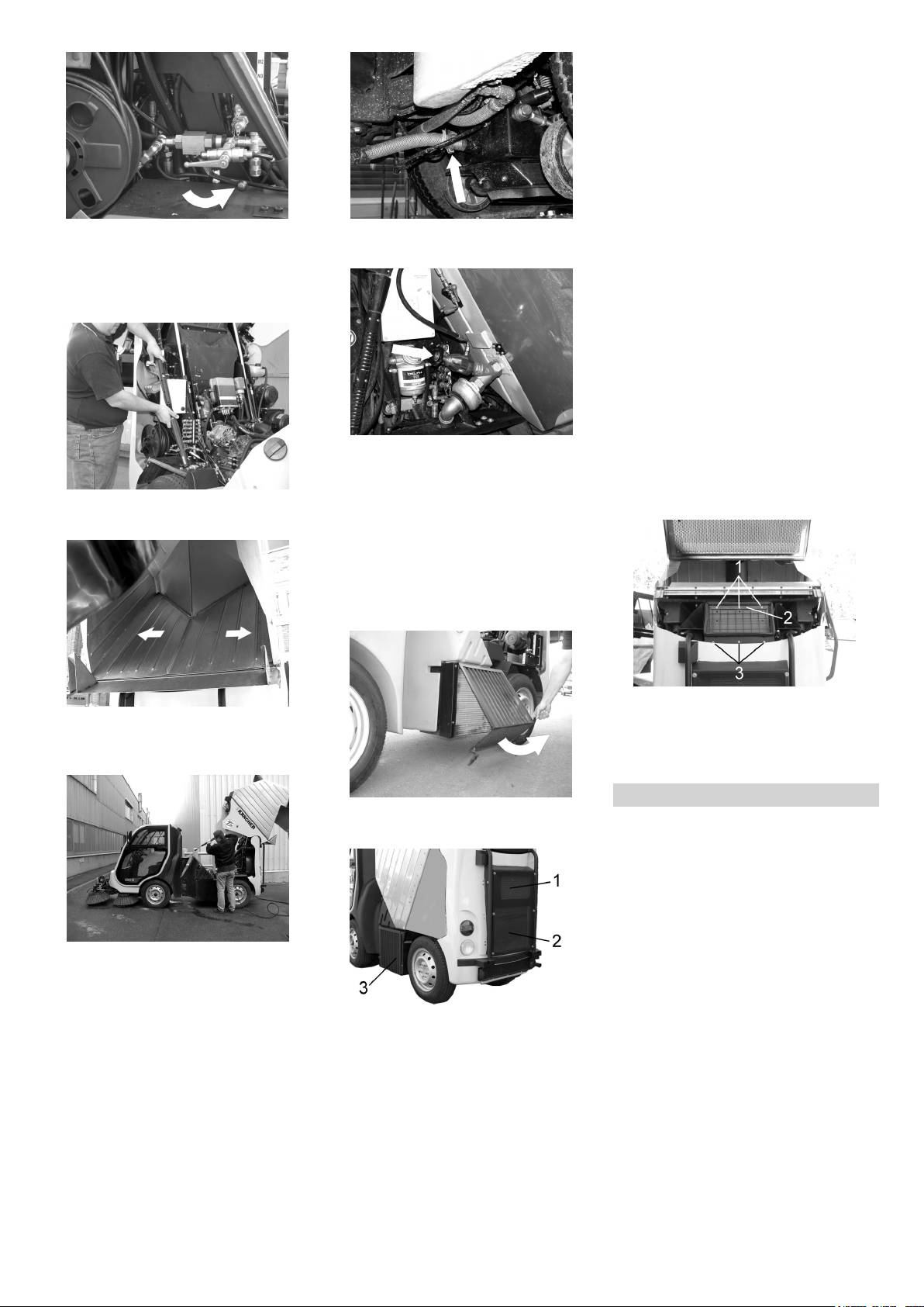
Cleaning the suction channel and the
waste container
Start the appliance.
Set the dry run speed to approx. 1800
1/min.
Turn on the working hydraulics (1st lev-
el).
Place the water hose in front of the suc-
tion opening.
Switch on the suction turbine and the
Shift the water supply to the side-brush-
Remove the suction hose from the claw
side-brushes (2nd step).
es and suction opening to operating
coupling under the vehicle.
Note
with high pressure cleaning.
Let the suction turbine run for approx. 2
Turn on the high-pressure cleaner.
minutes.
Raise waste container.
Cleaning the covering grid of the suction
channel
Raise waste container.
Switch off engine.
Clean the covering grid.
Cleaning the suction channel
Raise waste container.
Open the hand wheel of the valve by
Switch off engine.
turning it in anti-clockwise direction.
Danger
Connect the hoses at the claw coupling
Risk of injury! Wait for at least 1 minute until
Remove the hand-spray gun.
to the water supply and rinse.
the blower wheel stops rotating.
Wind off the high pressure hose.
Remove the connection to the water
supply and join the hose back to the
suction opening.
Close by turning the hand wheel of the
valve in clockwise direction.
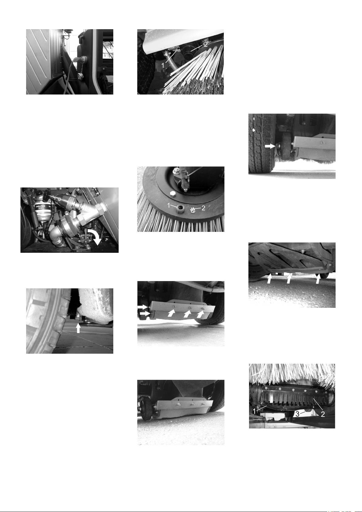
Clean the cooler
Remove the upper screws (1).
Clean the waste container.
Remove the strip (2).
Clean the perforated plate of the water
Loosen the lower screws (3).
drain on both the sides.
Remove the covering grid and clean the
suction channel.
Maintenance intervals
Open the clamps of the covering grid.
Remove the covering grid.
Note
The operating meter of the motor shows
the timing of the maintenance intervals.
Maintenance by the customer
Daily maintenance:
Clean the lighting.
Check engine oil level.
Clean the sealing areas of the suction
Check the hydraulic oil level.
channel.
Clean the cooler.
Clean the side-brushes.
Clean the covering grid of the suction
Clean the suction opening.
channel.
Clean the bulk waste flap.
1 Cooler for air-conditioner (accessory)
Check cooler water level.
Clean the hose connections.
2 Oil cooler
Check the air filter, clean if required.
If the hose connection between the waste
3 Water cooler
Check tube air filter/ motor.
container and the suction opening is
– Clean the cooler only when the motor
Check the side-brushes and suction
blocked, then proceed as follows:
has been switched off.
opening for wear and wrapped belts.
– Use a low-pressure water jet or com-
Check function of all operator control el-
pressed air to clean the cooler accord-
ements.
ing to the procedure described above.
Weekly maintenance:
– Do not clean using a high-pressure
Check sealing washer of suction pipe.
cleaner.
Check washers of the waste container.
Grease the bearings.
Check tyre pressure.
- 11
33EN
Check water level of wiper.
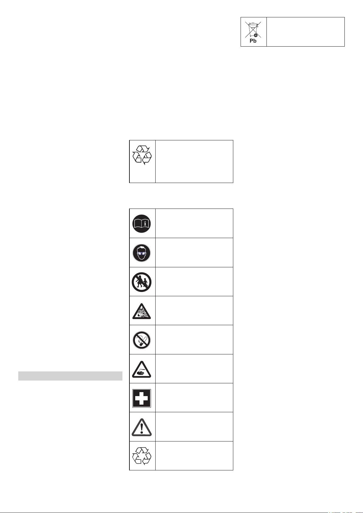
upward and lower the brush system to re-
Do not throw the battery in the
Clean water filter (frequently depending
move the pressure from the hydraulic sys-
dustbin!
on the water quality).
tem.
Check oil level of the water pump.
Danger
Check functioning and easy movement
Risk of injury! Secure the lid while working
Danger
of the bulk-waste flap.
inside the waste container.
Follow accident prevention regulations as
Check rollers to see that they move
Danger
well as DIN VDE 0510, VDE 0105 T.1.
easily.
Risk of injury due to engine overrun. Once
Danger
Lubricate the side-brush system.
the engine has been switched off, wait for 5
Risk of explosion! Do not put tools or similar
Additional maintenance to be carried out
seconds. Stay well clear of the working
on the battery, i.e. on the terminal poles
every 50 operating hours:
area for this time.
and cell connectors.
Check the function of the immobilizing
Allow the machine sufficient time to cool
brake.
Danger
down before carrying out any mainte-
Check the hydraulic system for leakag-
nance and repair work.
Risk of injury! Ensure that wounds never
es.
come into contact with lead. Always clean
– Cooling water is hot.
Check V-Belt for wear and tear.
your hands after having worked with batter-
– Do not touch any hot parts, such as the
ies.
Check coolant to see that it does not
drive motor and exhaust system.
frost.
Danger
Please do not release engine
Check hoses and clamps.
Risk of fire and explosion!
oil, fuel oil, diesel and petrol
Check wheels.
– Smoking and naked flames are strictly
into the environment. Protect
Check connections and conduits.
prohibited.
the ground and dispose of
Additional maintenance to be carried out
– Rooms where batteries are charged
used oil in an environmentally-
every 150 operating hours:
must have good ventilation because
clean manner.
Change engine oil.
highly explosive gas is emitted during
charging.
Replace motor oil filter inlay.
Safety notes regarding the batteries
Change the air filter.
Please observe the following warning notes
Danger
Empty the wate separator at the fuel fil-
when handling batteries:
Danger of causticization!
ter.
– Rinse thoroughly with lots of clear water
Observe the directions on the
Check battery acid level.
if acid gets into the eye or comes in con-
battery, in the instructions for
tact with the skin.
Clean the ventilation slits of the lights.
use and in the vehicle operat-
– Then consult a doctor immediately.
For description, see section on Mainte-
ing instructions!
nance work.
– Wash off the acid If it comes in contact
Wear an eye shield!
with the clothes.
Note
Where maintenance is carried out by the
Installing and connecting the battery
customer, all service and maintenance
Raise waste container.
work must be undertaken by a qualified
Insert battery in battery mount.
Keep away children from acid
specialist. If required, a specialised Kärch-
Screw on mounts on battery base.
and batteries!
er dealer may be contacted at any time.
Connect pole terminal (red cable) to
Maintenance by Customer Service
positive pole (+).
Maintenance to be carried out after 50 op-
Connect pole terminal to negative pole
Risk of explosion!
erating hours:
(-).
Carry out initial inspection.
Note
Additional maintenance to be carried out
Before removing the battery, make sure
every 150 operating hours:
that the negative pole lead is disconnected.
Fire, sparks, open light, and
Note
Check that the battery pole and pole termi-
smoking not allowed!
In order to safeguard warranty claims, all
nals are adequately protected with pole
service and maintenance work during the
grease.
warranty period must be carried out by the
Check fluid level in the battery and ad-
Danger of causticization!
authorised Kärcher Customer Service in
just if required
accordance with the maintenance booklet.
몇 Warning
Maintenance Works
Regularly check the fluid level in acid-filled
batteries.
Preparation:
First aid!
– The acid in a fully charged battery has a
Park the sweeper on an even surface.
specific weight of 1.28 kg/l at a temper-
Raise waste container completely.
ature of 20 °C.
Lower the side-brushes.
– The acid in a partially discharged bat-
Turn ignition key to "0" and remove it.
Warning note!
tery has a specific weight between 1.00
Lock parking brake.
and 1.28 kg/l.
Danger
– The specific weight of the acid must be
When carrying out repairs on public high-
uniform in all cells.
ways, wear warning clothing when working
Disposal!
Unscrew all cell caps.
close to passing traffic.
Take a sample from each cell using the
General notes on safety
acid tester.
Put the acid sample back into the same
Danger
cell.
Risk of injury! While carrying out mainte-
nance tasks, tilt the waste container fully
34 EN
- 12
Where fluid level is too low, top up cells
Use suitable, commercially available
Check engine oil level and top up, if re-
to the mark provided with distilled wa-
materials to carry out tyre repairs.
quired
ter.
Note
Danger
Charge battery.
Observe the manufacturer's recommenda-
Risk of burns!
Screw in cell caps.
tions. The journey may be resumed provid-
Allow engine to cool down.
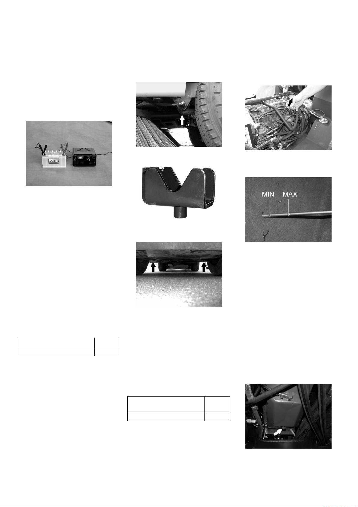
Charging battery
ing that the directions supplied by the
Wait for at least 5 minutes after switch-
product manufacturer have been observed.
Danger
ing off the engine before checking the
The tyre/wheel change should nonetheless
Risk of injury! Comply with safety regula-
engine oil fill level.
be carried out as soon as possible.
tions on the handling of batteries. Observe
Raise waste container.
the directions provided by the manufacturer
of the charger.
Danger
Charge the battery only with an appropriate
charger.
Intake point for the jack (front wheels)
Pull out oil dipstick.
Wipe off oil dipstick and insert.
Pull out oil dipstick.
Disconnect battery.
Connect positive terminal cable from
the charger to the positive pole connec-
tion on the battery.
Connect negative terminal cable from
the charger to the negative pole con-
Use the corresponding intake delivered
nection on the battery.
along with the vehicle.
Plug in mains connector and switch on
charger.
Read the value of the oil level.
Charge battery using lowest possible
Insert the oil dip again.
level of charging current.
– The oil level must lie between “MIN“
Note
and “MAX“ marking.
When the battery is charged, first remove
– Add motor oil if the oil level is below the
the charger from the mains and then dis-
"MIN" marking.
connect it from the battery.
– Do not fill oil above the "MAX" marking.
Check the tyre pressure
Loosen the screw cap of the oil filling
Park the sweeper on an even surface.
opening.
Connect air pressure testing device to
Fill in motor oil.
Intake point for the jack (rear wheels)
tyre valve.
Position vehicle jack at the appropriate
Oil grade: see Technical Data
Check air pressure and adjust if re-
mounting point for the front or rear
Close oil filler opening.
quired.
wheel.
Wait at least 5 minutes.
Loosen wheel nuts/ wheel bolts.
Check engine oil level.
Air pressure, front 3,75 bar
Raise machine using vehicle jack.
Change the motor oil and the oil filter
Air pressure, rear 4,75 bar
Remove wheel nuts/ wheel bolts.
Danger
Replacing wheel
Remove wheel.
Risk of burns due to hot oil!
Mount spare wheel.
Danger
Ready a catch bin for appr. 6 litre oil.
Insert the wheel nuts/ wheel bolts.
When carrying out repairs on public high-
Allow engine to cool down.
Lower machine using vehicle jack.
ways, wear warning clothing when working
close to passing traffic.
Tighten the wheel nuts/ wheel bolts.
Danger
Tightening torque for front
140 Nm
Risk of injury!
tyres
Park the sweeper on an even surface.
Tightening torque for rear tyres 120 Nm
Remove ignition key.
Check stability of ground. Also secure
Note
the machine with wheel chock(s) to pre-
Use a suitable commercially available vehi-
vent it rolling away.
cle jack.
Lock parking brake.
Check tyres
Unscrew oil drain plug.
Check tyre contact face for foreign ob-
Loosen the screw cap of the oil filling
jects.
opening.
Remove objects found.
Drain off oil.
- 13
35EN
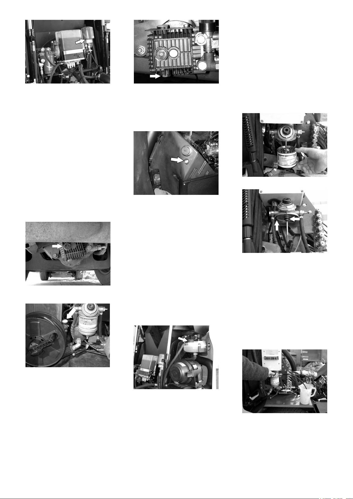
Clean and replace fuel filter
Danger
Risk of explosion!
– Do not carry out maintenance tasks in
closed rooms.
– Smoking and naked flames are strictly
prohibited.
Switch off engine.
Raise waste container.
Keep a suitable catch bin ready.
Unscrew the oil filter.
Oil change:
Loosen the fuel filter casing.
Clean the intake and sealing areas.
Ready a catch bin for appr. 1 litre oil.
Empty the fuel filter casing.
Coat the washer of the new oil filter with
Unscrew oil drain plug.
Remove the fuel filter casing.
oil before fitting it.
Oil grade: see Technical Data
Fit in the new oil filter and tighten it by
Check hydraulic oil level and refill hy-
hand.
draulic oil
Screw in the oil drain screw along with
the new washer.
Note
Tighten the oil drain screw using a torque
wrench to 25 Nm.
Fill in motor oil.
Oil grade: see Technical Data
Close oil filler opening.
Clean or replace fuel filter.
Let the motor run for approx. 10 sec-
onds.
Check engine oil level.
The oil level must be within the viewing
glass.
Check oil level in the water pump; refill
Clean the filling area.
and change oil
Loosen the screw cap of the oil filling
opening.
Refill hydraulic oil.
Oil grade: see Technical Data
Check hydraulic unit
Check all hydraulic hoses and connec-
Replace washers.
tions and ensure that they are leak-
Fit the fuel filter again.
proof.
Check fuel tubes and clamps for dam-
Only Kärcher Customer Service is author-
ages and make sure they are leak-
ised to carry out maintenance tasks on the
proof.
The oil level must be within the viewing
hydraulic unit.
Deaerate the fuel system
glass.
Check water cooler and maintain it
Deaerating the fuel system
Danger
Raise waste container.
Danger of scalding by boiling water! Let the
Insert the hose on the deaeration
cooler cool down for at least 20 minutes.
screw.
Turn the deaeration screw by one rota-
tion.
Keep a suitable catch bin ready.
Refill oil:
Clean the filling area.
Loosen the screw cap of the oil filling
opening.
Fill in cold water in the cooling water
Refill oil.
compensation tank.
Close oil filler opening.
If the motor is cold:
Check oil level.
– Cooling water level must be above the
Pump until fuel free of air bubbles is re-
lower marking.
leased.
If the motor is warm:
Close the deaeration screw.
– Cooling water level must be below the
upper marking.
– The percentage of anti-frost agent in
the cooling water should not be more
than 50%.
36 EN
- 14
Emptying the water separator of the fuel
system
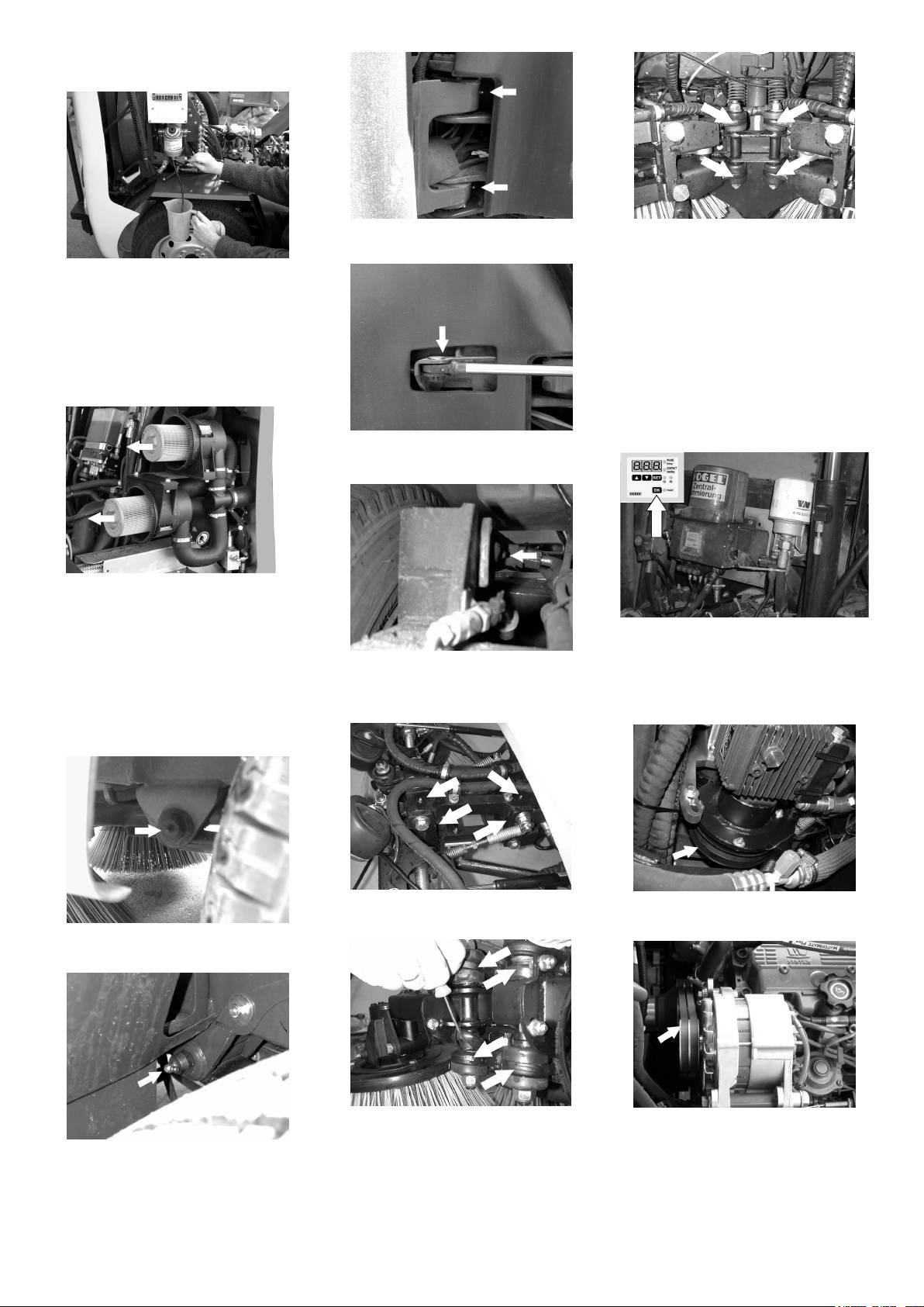
Grease the lubrication nipple at the
Only 4-brush system:
swivel joint.
Lift the covering flaps at the swivel
heads.
Raise waste container.
Grease the swivel joints (8x).
Insert the hose on the drain screw.
Turn the drain screw by one rotation.
Central lubrication unit (accessory)
Keep a suitable catch bin ready.
The central lubrication unit automatically lu-
Close the release screw.
brications all the lubrication points at spec-
ified intervals.
Cleaning and replacing the fuel filter
Note
Raise waste container.
It is necessary to do an additional round of
greasing after the appliance has been
cleaned thoroughly.
Grease the lubrication nipple at the
steering cylinder.
Loosen the fasteners of the air filter
casing.
Remove covering lid.
Press the button on the central lubrica-
Remove and clean the filter cartridge.
tion unit.
Insert new filter cartridge, if required.
Grease the lubrication nipple at the
The central lubrication unit will not lubricate
Clean the screw cap.
steering cylinder.
the brush-system.
Replace the screw cap and clamp it.
Greasing the brush-system
Checking the V-Belt
Fix the fasteners of the air filter casing.
Greasing the bearings
Grease the lubrication nipple at the
Check the V-Belt of the spray-water
brush-system (8x).
pump for damage and wear and tear.
Grease the left end right lubrication nip-
ples of the front axle.
Only 4-brush system:
Raise waste container.
Lift the covering flaps at the swivel
Check the V-Belt of the lighting system
Grease the left end right lubrication nip-
heads.
for damage and wear and tear.
ples of the rear axle.
Grease the swivel joints (8x).
Refilling wiper water
Refill water for the wiper.
- 15
37EN
Drive machine backwards.
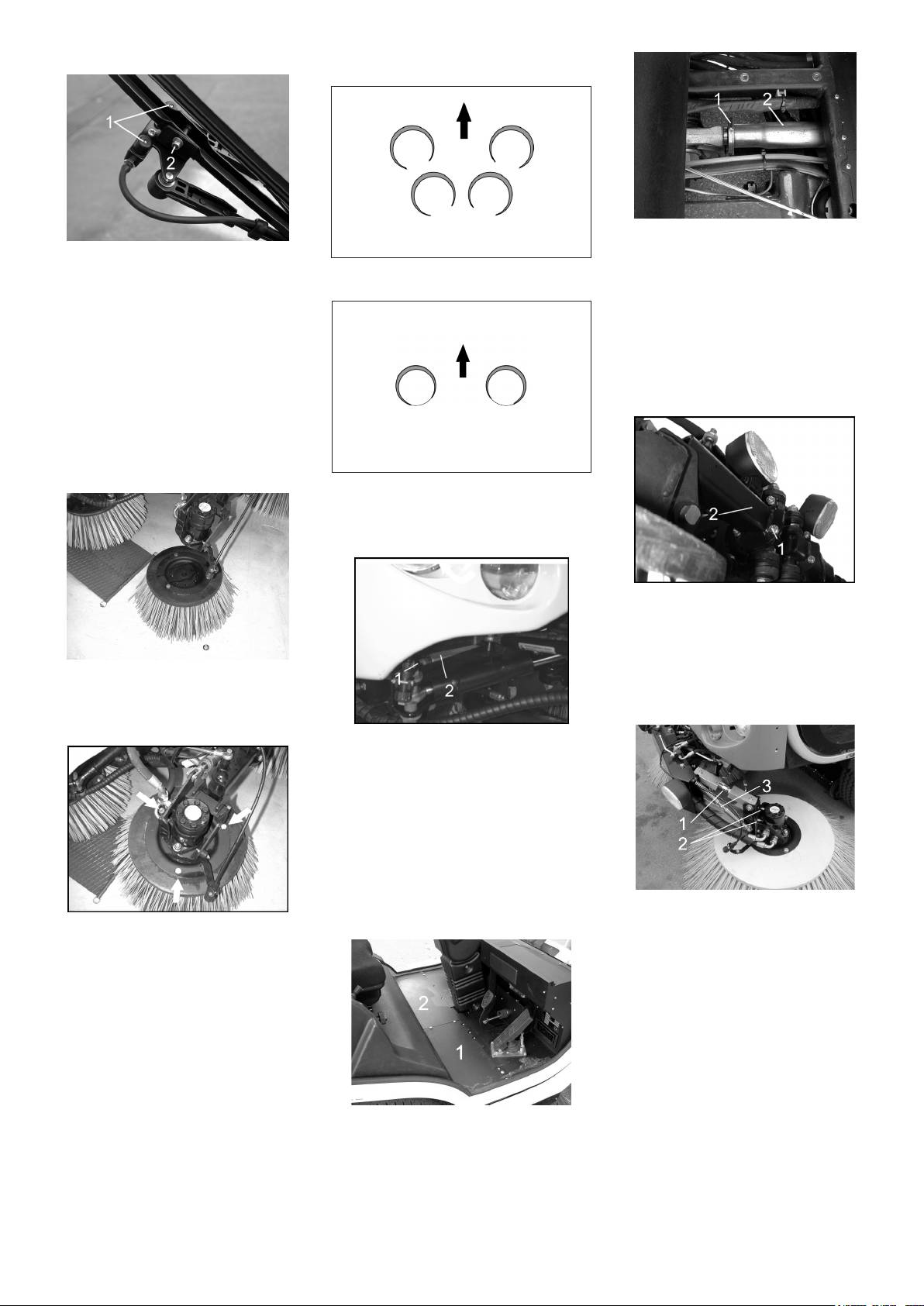
Maintaining the wiper
Check sweeping mirror.
Loosen the fastening screw (1).
Clean/ set the spray nozzles:
Adjust the inclination of the side-brush-
Clean the spray nozzle opening (1) us-
Contact surfaces of the side-brushes dur-
es in the drive direction by adjusting the
ing a wire.
ing optimal setting (4-brush system).
holder (2).
Adjust the spraying direction by turning
Note
the spray head with a wire.
Set the left and right side always at the
Change the wiper blades:
same value.
Remove the fastening screw (2).
Adjusting the inclination of the front
Change the wiper blade.
side-brushes in drive direction (only 4-
Replacing side brush
brush system)
Lock parking brake.
The side-brushes lift up.
Clip side brush on to driver and screw
on.
Contact surfaces of the side-brushes dur-
ing optimal setting (2-brush system).
Adjusting the side inclination of the rear
side-brushes (only 4-brush system)
Loosen the fastening screws (1) of the
side-brush attachment .
Adjust the inclination of the side-brush-
es in the drive direction by turning the
holder (2).
Changing the wiper blade with the intake:
Loosen the central screw.
Adjusting the inclination of the side-
Remove the wiper blade.
brushes (only 2-brush system)
Fix in the new wiper blade.
Loosen the fastening screw (1).
Adjust the side inclination of the side-
brushes by adjusting the holder (2).
Adjusting the inclination of the rear side-
brushes in drive direction (only 4-brush
system)
Note
Always set the rear side-brushes first be-
cause changes to the rear inclination will
have an effect on the inclination of the front
Loosen the fastening screws (1) and (2)
brushes.
of the side-brush attachment .
Changing the wiper blade without the in-
take:
Set the inclination of the side-brushes.
Loosen the hexagonal nuts:
Setting the brush contact pressure
Remove the wiper blade.
Increase/ reduce the brush pressure by
Fix in the new wiper blade.
adjusting the setting screw (3).
Checking the sweeping mirror of the
Note
side-brushes
In the 4-brush system, the contact pressure
Check tyre pressure and adjust if re-
can only be set for the front side-brushes.
quired.
Set the idle running for the motor rpm
setting to 1600-1800 1/min.
Remove floor mat.
The side-brushes lift up.
Remove the floor plates (1) and (2).
Drive sweeper on to a smooth, even
surface covered with a visible layer of
dust or chalk.
Lower side-brushes and allow them to
briefly rotate.
The side-brushes lift up.
38 EN
- 16
Loosen the fastening screws of the
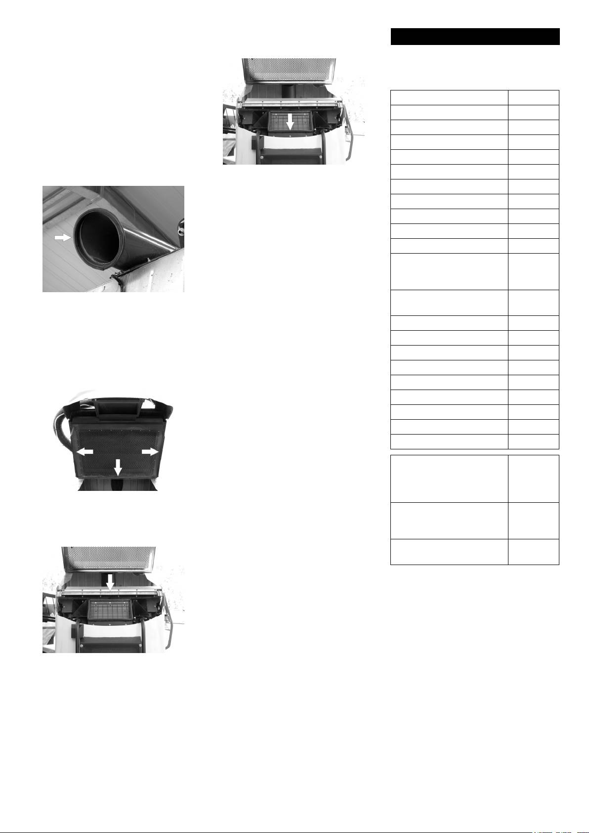
Filling up the water tank
Cleaning and replacing the water filter
sealing strip.
Remove the stabilising plate.
Remove the sealing strip.
Insert the new sealing strip and fasten it
with screws along with the stabilising
plate.
Drain off the suction opening.
Adjust the sealing strip.
Tighten the fastening screws of the
sealing strip.
Unscrew the tank coupling.
Turn off tap (1).
Changing the running rollers of the suc-
Connect a textile hose to the tank cou-
Unscrew the water filter casing (2).
tion opening (only 4-brush system)
pling and hydrant.
Clean or replace the water filter.
Fill up the water tank:
Clean the water filter casing.
Note
Check rubber washers.
Fill up the water tank until it overflows.
Install the water filter.
Turn on the tap (1).
Deaerating the spray-water system
Note
Cleaning the spray nozzles on the side-
If the water tank had got completely empty,
brushes
then it is necessary to deaerate the spray
water system after the tank has been filled
up.
Remove wheel.
Remove the fastening nuts of the run-
ning rollers.
Replace the running rollers.
Replace the fastening nuts of the run-
ning rollers.
Changing the slide bar of the bulk waste
flap (only 4-brush system)
Unscrew the union joint (1).
Pull out the spray nozzle (2).
Clean the spray nozzle.
Open the valve until bubble free water
Setting and replacing the sealing strip of
comes out.
the suction opening (only 4-brush sys-
Now close the valve.
tem)
Emptying the water tank
Remove the fastening screws of the
slide bar.
Replace the side bar.
Fasten the slide bar.
Setting and replacing the sealing strip of
the suction opening (only 2-brush sys-
Adjusting the sealing strip:
tem)
Open the drain screw below the water
Loosen the fastening screws of the
tank.
sealing strip.
Note
Drain off the suction opening.
Ensure that the water flowing out does not
cause any damage.
Adjusting the sealing strip:
Loosen the screws.
Drain off the suction opening.
Adjust the sealing strip on the side and
the rear so as to have a distance of 10
Adjust the rear running rollers (3) in
mm from the floor.
such a way that the side sealing strip (1)
has a floor clearance of 20 mm at the
Tighten the fastening screws of the
rear.
sealing strip.
Replacing the sealing strip:
- 17
39EN
Adjust the front sealing strip (2) so that
Changing the washer of the turbine suc-
Accessories
it touches the floor.
tion
Tighten the fastening screws of the
Note
sealing strip.
Attachment sets for new vehicles are also
Replacing the sealing strip:
available ex-factory.
Loosen the screws.
Spare wheel, complete 6.996-001
Remove the sealing strip.
Screw on the new sealing strip.
Bush plate 6.996-002
Drain off the suction opening.
Side brushes, plastic/ plastic 6.996-003
Adjust the sealing strip.
Side-brushes, steel plate 6.996-004
Tighten the fastening screws of the
sealing strip.
Side-brushes, PE/Steel 6.906-258
Changing the washer of the suction pipe
Remove the washer.
Breakdown triangle 6.996-005
Clean the sealing area.
Bulbs/ fuse set 6.996-006
Insert the new washer and paste it.
Wheel wedge 6.996-007
Changing the headlight bulb
Air-conditioner 2.639-614
Loosen the screws.
Radio 2.639-615
Remove the headlights.
Remove defective bulb.
Leaf suction hose 2.639-616
Insert new bulb.
Overall warning lamp, rear
2.639-617
Changing the bulb of the travel direction
(only for appliances without
indicator
leaf suction)
Loosen the screws.
Comfort seat (higher back-
2.639-618
Raise waste container.
Remove the glass of the travel direction
rest)
Remove the washer.
indicator.
Clean the sealing area.
Rear mirror, with heating 2.639-619
Remove defective bulb.
Insert the new washer and paste the
Battery charger 6.654-116
Insert new bulb.
ends using silicon.
Central lubrication unit 2.639-635
Replacing the bulb of the tail lamp
Changing the washer of the waste con-
Loosen the screws.
Bumper at the rear 2.639-636
tainer
Remove the glass of the tail lamp.
Reverse drive camera 2.639-641
Remove defective bulb.
Jack 6.369-518
Insert new bulb.
Hose holder for filling hose 2.639-645
Replacing the fuses in the fuse box in
the driver cabin
Safety warnings 2.639-869
Note
Hydraulic side-brush relief 2.850-816
Only use fuses with identical safety ratings.
2. Regulation valve (for reg-
2.640-216
Replace defective fuses.
ulating the spray water
Replacing the fuses in the fuse box of
quantity separately on the
the motor compartment
right and the left)
Raise waste container.
Replace defective fuses.
Remove the washer.
Solenoid valve (for stopping
2.640-217
Clean the sealing area.
the spray water and lifting
the brushes)
Insert the new washer and paste it.
Attachment set for bypass
2.641-197
valve
Remove the washer.
Clean the sealing area.
Insert the new washer and paste it us-
ing silicon.
40 EN
- 18
