Karcher HDS 7-16 4C Basic – страница 2
Инструкция к Системе Водяного Охлаждения Karcher HDS 7-16 4C Basic
Please read and comply with
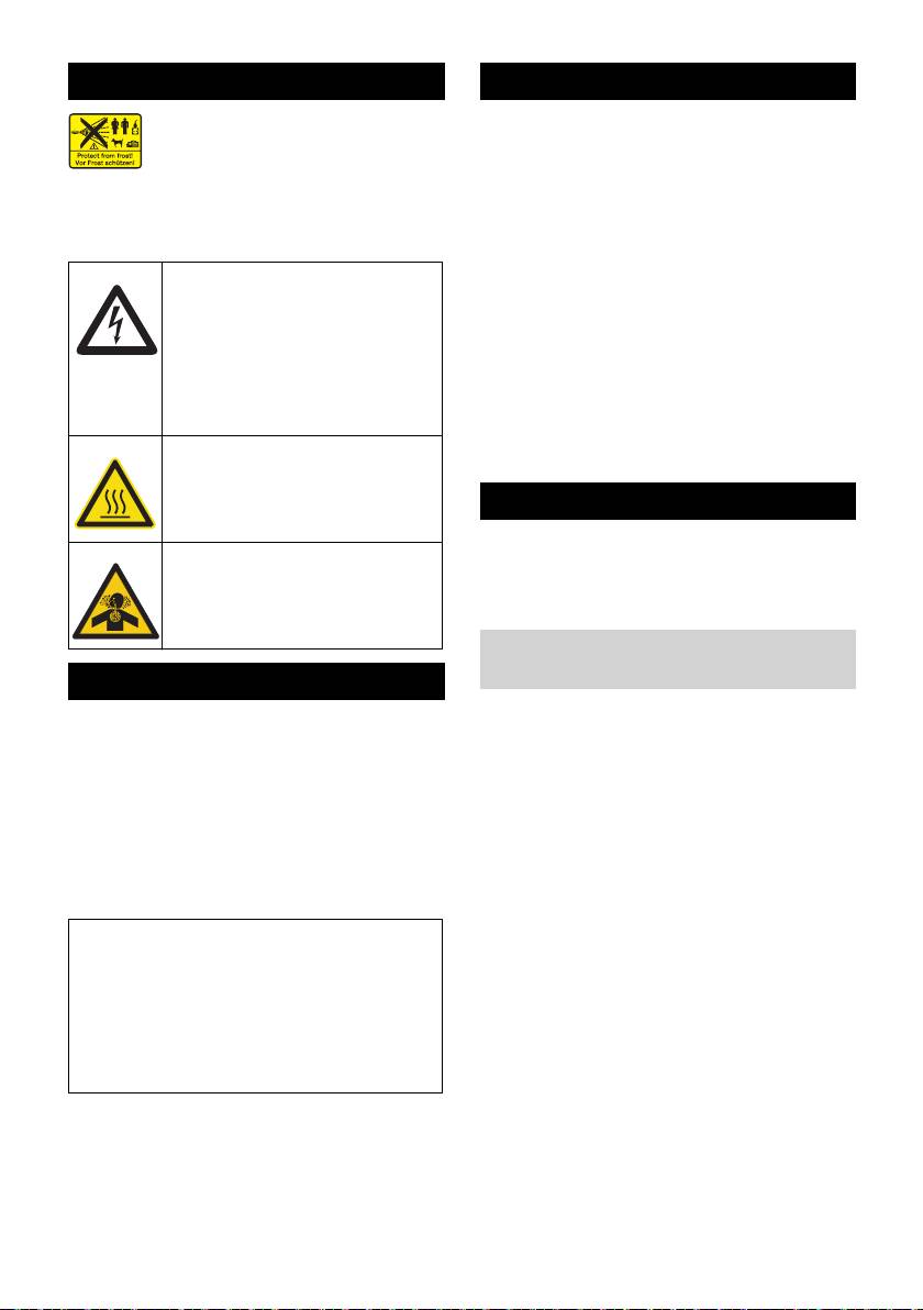
Environmental protection
these original instructions prior
to the initial operation of your appliance and
The packaging material can be
store them for later use or subsequent own-
recycled. Please do not throw
ers.
the packaging material into
– Before first start-up it is definitely nec-
household waste; please send it
essary to read the operating instruc-
for recycling.
tions and safety indications Nr. 5.951-
Old appliances contain valuable
949.0!
materials that can be recycled;
– In case of transport damage inform ven-
these should be sent for recy-
dor immediately
cling. Batteries, oil, and similar
– Check the contents of the pack before
substances must not enter the
unpacking. For scope of delivery see il-
environment. Please dispose of
lustration 1.
your old appliances using ap-
Contents
propriate collection systems.
Environmental protection . . EN . . .1
Please do not release engine oil, fuel oil,
diesel and petrol into the environment Pro-
Symbols in the operating in-
structions . . . . . . . . . . . . . . EN . . .1
tect the ground and dispose of used oil in
Overview . . . . . . . . . . . . . . EN . . .2
an environmentally-clean manner.
Symbols on the machine . . EN . . .2
Notes about the ingredients (REACH)
Proper use . . . . . . . . . . . . . EN . . .3
You will find current information about the
Safety instructions . . . . . . . EN . . .3
ingredients at:
Safety Devices . . . . . . . . . . EN . . .3
www.kaercher.com/REACH
Start up. . . . . . . . . . . . . . . . EN . . .3
Symbols in the operating
Operation . . . . . . . . . . . . . . EN . . .5
instructions
Storage. . . . . . . . . . . . . . . . EN . . .8
Transport . . . . . . . . . . . . . . EN . . .8
Danger
Maintenance and care . . . . EN . . .8
Immediate danger that can cause severe
Troubleshooting . . . . . . . . . EN . . .9
injury or even death.
Warranty. . . . . . . . . . . . . . . EN . . 11
몇 Warning
Accessories and Spare Parts EN . . 11
Possible hazardous situation that could
EC Declaration of Conformity EN . .12
lead to severe injury or even death.
Technical specifications . . . EN . .13
Caution
Possible hazardous situation that could
lead to mild injury to persons or damage to
property.
– 1
21EN
38 Backflow valve of the detergent infeed
Overview
39 Detergent suction hose with filter
40 Fuel filter
Device elements
41 Fastening clamp
Figure 1
42 Hose of the lack of water fuse
1 Support for spray lance
43 Water shortage safeguard
2 Recess for detergent suction hose
44 Sieve in the water shortage safeguard
3 Recessed grip (both sides)
45 Fine filter (water)
4 Wheel
46 Float tank
5 Connection for water supply with filter
Operating field
6 Water supply set
7 O-ring set (for replacement)
Figure 2
8 High pressure connection
A Power switch
9 High pressure hose
1 Indicator lamp rotation direction
10 Spray lance
(3-phase appliances only)
11 High-pressure nozzle (stainless steel)
2 “Ready for use” indicator lamp
12 Pouring vent for detergent
3 Fuel indicator lamp
13 Steering roller with fixed position brake
4 Indicator lamp service
14 Fuel sieve
Colour coding
15 Safety latch of the hand spray gun
– The operating elements for the cleaning
16 Hand spray gun
process are yellow.
17 Power supply
– The controls for the maintenance and
18 Tool bag (HDS C only)
service are light gray.
19 Pouring vent for fuel
20 Dosage valve for detergent
Symbols on the machine
21 Operating field
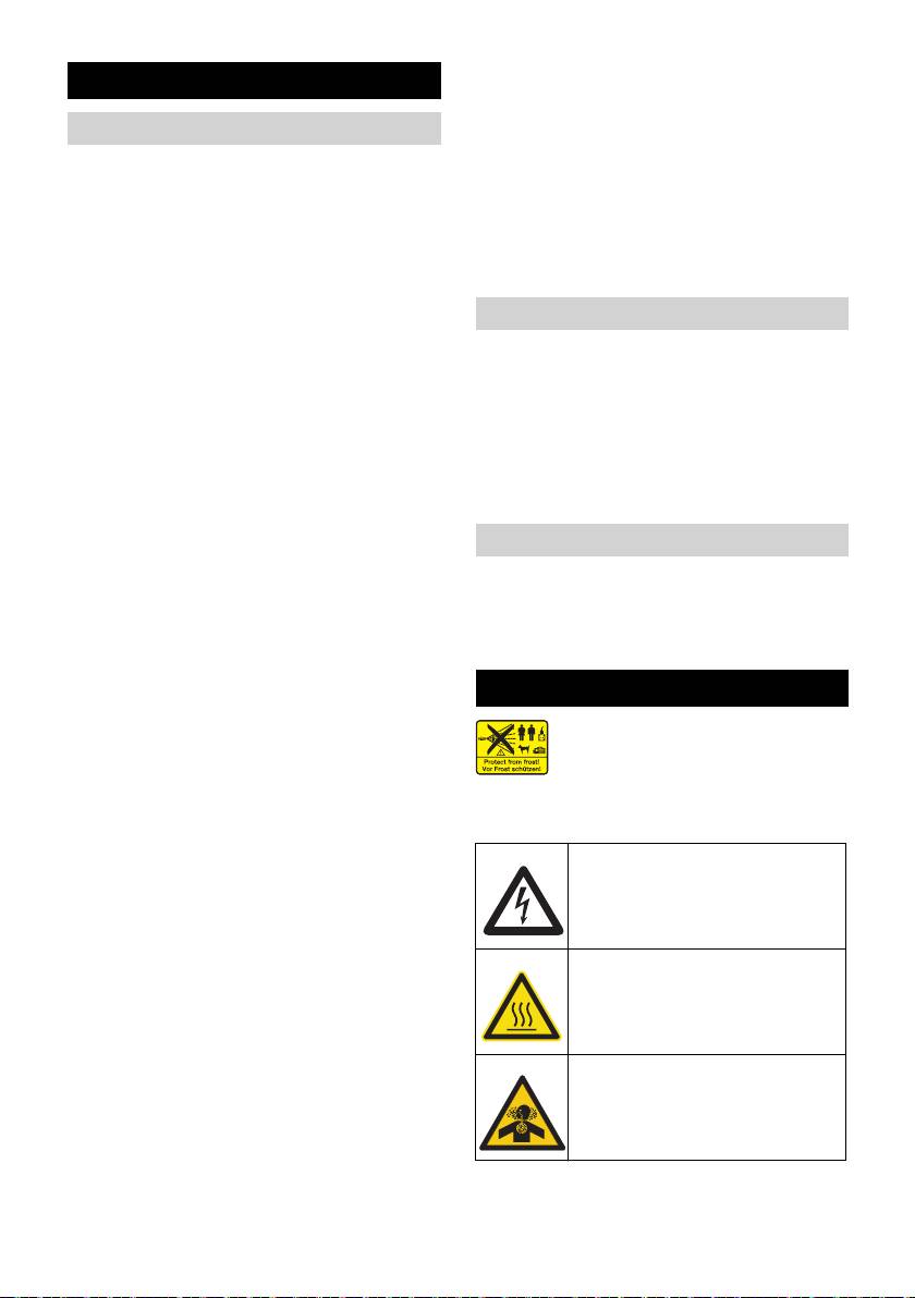
High-pressure jets can be dan-
22 Storage for hand spray gun
gerous if improperly used. The
23 Connecting hose of the hose drum
jet may not be directed at per-
(HDS CX only)
sons, animals, live electrical equipment or
24 Step depression
at the appliance itself.
25 Hose drum (HDS CX only)
Risk of electric shock!
26 Hand crank for hose drum
Only electricians or authorised
(HDS CX only)
technicians are permitted to
27 Handle
work on parts of the plant.
28 Nameplate
Risk of burns on account of hot
29 Cover lock
surfaces!
30 Storage compartment for accessories
31 Burner
32 Recess for spray pipe
Risk of poisoning! Do not
33 Cover
breathe in the exhaust fumes.
34 System care Advance RM 110/RM 111
35 Pressure/quantity regulation of the
pump unit
36 Oil tank
37 Oil drain screw
22 EN
– 2

– If the hand spray gun is opened, the
Proper use
pressure switch on the cylinder head
Cleaning of: Machines, Vehicles, Struc-
turns the pump back on.
tures, Tools, Facades, Terraces, Garden-
The overflow valve is set by the manufac-
ing tools, etc.
turer and sealed. Setting only by customer
service.
Danger
Risk of injury! Follow the respective safety
Safety valve
regulations when operating at gas stations
– The safety valve opens, when the over-
or other dangerous areas.
flow valve resp. the pressure switch is
Please do not let mineral oil contaminated
broken.
waste water reach soil, water or the sew-
The safety valve is set by the manufacturer
age system. Perform engine cleaning and
and sealed. Setting only by customer service.
bottom cleaning therefore only on speci-
Water shortage safeguard
fied places with an oil trap.
– The water shortage safeguard prevents
Safety instructions
the burner to be turned on when there is
water shortage.
– Please follow the national rules and
– A sieve prevents the contamination of
regulations for fuel spray jets of the re-
the safeguard and must be cleaned reg-
spective country.
ular.
– Please follow the national rules and
regulations for accident prevention of
Temperature stop for exhaust gases
the respective country. Fuel spray jets
– The temperature stop switches off the
must be tested regularly and the results
machine when the waste gases have
of these tests must be documented in
reached very high temperatures.
writing.
– The heating appliance of the machine is
Start up
an ignition plant. All national laws and
몇 Warning
regulations about heating systems must
also be followed.
Risk of injury! Device, tubes, high pressure
hose and connections must be in faultless
Safety Devices
condition. Otherwise, the appliance must
not be used.
Safety devices serve for the protection of the
Lock parking brake.
user and must not be put out of operation or
bypassed with respect to their function.
Installing the handle
Overflow valve with two pressure
Figure 3
switches
Screw tightening torque: 6.5-7.0 Nm
– When the water supply at the pump
Install the tool bag (HDS C only)
head is reduced, the overflow valve
Figure 4
opens and part of the water flows back
Hook the tool bag onto the top tabs on
to the suction side of the pump.
the appliance.
– If the hand-spray gun is closed, so that
Tilt the tool bag down and lock it into
the whole water flows back to the pump
place.
suck side, the pressure switch at the
Fasten the tool bag with 2 screws
overflow valve shuts down the pump.
(torque: 6.5 - 7.0 Nm).
Note: 2 screws are left over.
– 3
23EN

Install the hose drum (HDS CX only)
Replace the system care bottle
Figure 5
Note: Push the bottle in securely to pene-
Hook the hose drum onto the bottom
trate the closure. Do not remove bottle until
tabs on the appliance.
it is empty.
Tilt the hose drum up and lock it into
– The system care prevents the calcifica-
place.
tion of the heating spiral while operating
with calciferous tap water. It is dosed
Fasten the hose drum with 4 screws
into the supply in the float container
(torque: 6.5 - 7.0 Nm).
drop by drop.
Connect the connecting hose of the
– The metering is set to medium water ri-
hose drum to the high pressure connec-
gidity by the manufacturer
tion point of the appliance.
Note: A system care bottle is included in
Install the hand-spray gun, the jet
the delivery.
pipe, the nozzle and the high
Replace the system care bottle.
pressure hose
Refill fuel
Figure 6
Connect ray tube with hand spray gun
Danger
Tighten the screw connection of the
Risk of explosion! Only refill diesel oil or
spray lance finger tight.
light fuel oil. Unsuitable fuels, e.g. petrol,
are not to be used.
Insert high pressure nozzle into cover-
ing nut
Caution
Install covering nut and tighten firmly
Never operate device with empty fuel tank
Appliance without hose drum:
The fuel pump will otherwise be destroyed.
Connect the high pressure hose to the
Refill fuel.
high pressure connection point of the
Close tank lock.
machine.
Wipe off spilled fuel.
Device with hose drum:
Refill detergent
Connect high pressure hose to hand
spray gun
Caution
Caution
Risk of injury!
– Use Kärcher products only.
Always unwind high pressure hose com-
pletely
– Under no circumstances fill solvents
(petrol, aceton, diluting agent etc.)
Installing spare high pressure hose
– Avoid eye and skin contact.
Unit without hose drum
– Observe safety and handling instruc-
Figure 7
tions by the detergent manufacturer.
Kärcher offers an individual cleaning
Device with hose drum
and care appliances program.
Figure 8
Your dealer will consult you gladly.
Completely roll off the high-pressure
Refill detergent.
hose from the hose drum.
Unlatch the fastening clamp for the
high-pressure hose and pull the hose
out.
Slide the hose nipple all the way into the
knot section of the hose drum and se-
cure with the fastening clamp.
24 EN
– 4

Danger
Water connection
Never suck in water from a drinking water
For connection values refer to technical
container. Never suck in liquids which con-
specifications
tain solvents like lacquer thinner, petrol, oil
Attach supply hose (minimum length
or unfiltered water. The sealings within the
7.5 m, minimum diameter 3/4“) to the
device are not solvent resistant. The spray
water supply set by means of a hose
mist of solvents is highly inflammable, ex-
clamp.
plosive and poisonous.
Connect the supply hose to the water
Assembly in reverse order.
connection point of the machine and at
Note: Ensure that the solenoid valve cable
the water supply point (for e.g. a tap).
on the reservoir of the system care is not
Note: The supply hose and the hose clamp
pinched.
are not included in the scope of delivery.
Figure 13
Note: After placing the back wall, reach into
Suck in water from vessel
the chute of the system care and press the
If you want to suck in water from an exter-
nozzle onto the system care reservoir.
nal vessel, the following modification is
Power connection
necessary:
Remove the system care bottle.
– For connection values, see technical
data and type plate.
Figure 9
– The electrical connections must be
Remove the two screws on the burner
done by an electrician according to IEC
casing.
60364-1.
Figure 10
Unscrew the back wall and remove it.
Danger
The nozzle of the system care reservoir
Danger of injury by electric shock.
will remain in the back wall.
– Unsuitable extension cables can be
Figure 11
hazardous. Only use extension cables
outdoors which have been approved for
Remove water connection from the fine
this purpose and labelled with a suffi-
filter.
cient cable cross section:
Unscrew the fine filter from the pump
– Always unwind extension lines com-
head.
pletely.
Remove the system care reservoir.
– The plug and coupling of the extension
Figure 12
cable used must be watertight.
Unscrew the top supply hose to the
swimmer container.
Operation
Connect the top supply hose at pump
Danger
head.
Risk of explosion!
Replug the rinse line of the detergent
Do not spray flammable liquids.
dosing valve to blind plugs.
Connect suction hose (minimum diame-
Danger
ter 3/4“) with filter (accessory) to the
Risk of injury! Never use the appliance
water connection point.
without the spray lance attached. Check
and ensure proper fitting of the spray lance
– Max. suck height: 0.5 m
prior to each use. The screw connection of
Until the pump sucked in water, you should:
the spray lance must be fingertight.
Set the pressure/quantity regulation at
Caution
the pump unit to maximum quantity.
Never operate device with empty fuel tank
Close the dosing valve for the deter-
The fuel pump will otherwise be destroyed.
gent.
– 5
25EN
Safety instructions
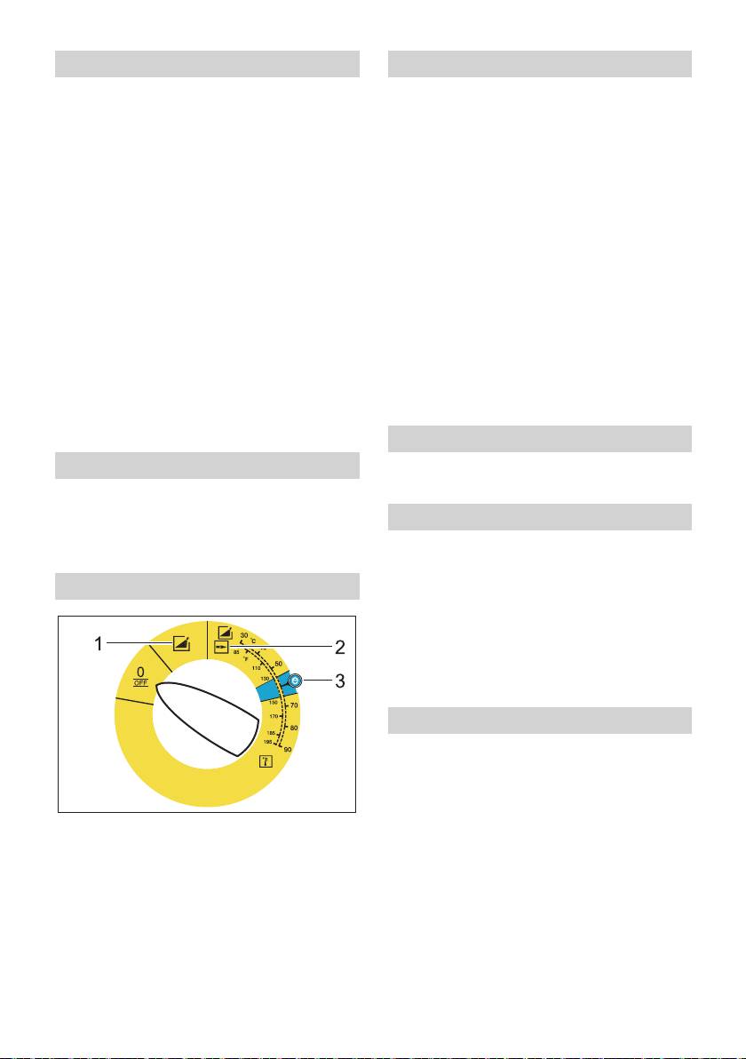
Turning on the Appliance
몇 Warning
Set appliance switch to desired operat-
ing mode.
Long hours of using the appliance can
Indicator lamp for operational readiness
cause circulation problems in the hands on
lights up.
account of vibrations.
It is not possible to specify a generally valid
The device starts briefly and turns off, as
operation time, since this depends on sev-
soon as the working pressure is reached.
eral factors:
Note: If the control lamp "rotation direction"
– Proneness to blood circulation deficien-
lights up, please switch the appliance off
cies (cold, numb fingers).
immediately and fix the error, see "Help
with malfunctions".
– Low ambient temperature. Wear warm
Release the trigger gun.
gloves to protect hands.
When activating the hand spray gun the de-
– A firm grip impedes blood circulation.
vice switches back on.
– Continuous operation is worse than an
Note: If no water comes out of the high
operation interrupted by pauses.
pressure nozzle, vent pump. Refer to "Help
In case of regular, long-term operation of
with malfunctions - appliance is not building
the device and in case of repeated occur-
up pressure".
rence of the symptoms (e.g. cold, numb fin-
gers) please consult a physician.
Adjust cleaning temperature
Replace the nozzle
Set device switch to desired tempera-
ture.
Danger
Switch the appliance off prior to replacing
Set working pressure and flow rate
nozzle and activate hand spray gun until
Pressure/quantity regulation of the
device is pressureless.
pump unit
Operating modes
Turn the regulation spindle in a clock-
wise direction: Increase working pres-
sure (MAX).
Turn the regulation spindle in an anti-
clockwise direction: Reduce working
pressure (MIN).
Operation with detergent
– For considerate treatment of the envi-
ronment use detergent economically.
– The detergent must be suitable for the
surface to be cleaned.
0/OFF =Off
With support of the detergent dose
1 Operating with cold water
valve set detergent concentration as
2 Operating with hot water
determined by the manufacturer.
3 Eco setting (hot water max. 60 °C)
Note: Recommended values at the control
panel at maximum working pressure.
Note: If detergent is be suctioned from an
external container, route the detergent suc-
tion hose through the recess to the outside.
26 EN
– 6

Cleaning
After operation with detergent
Set pressure/temperature and deter-
Set dosing value for detergent to "0".
gent concentration according to the sur-
Set the appliance switch to "1" (opera-
face to be cleaned.
tion with cold water).
Note: To prevent damage due to too much
Open the hand spray gun and rinse the
pressure, always position high pressure ray
appliance for at least 1 minute.
first from a greater distance towards object
Turn off the appliance
to be cleaned.
Recommended cleaning method
Danger
– Loosen the dirt:
Danger of scalding by hot water. After oper-
Spray detergent economically and let it
ation with hot water, the device must be op-
work for 1...5 minutes but do not let it
erated with open end handgun with cold
dry up.
water for at least two minutes.
– Remove the dirt:
Set the appliance switch to "0/OFF“.
Spray off loosened dirt with the high
Shut off water supply.
pressure jet.
Open the hand spray gun.
Turn on pump shortly (appr. 5 seconds)
Operating with cold water
with device switch.
Removal of light contaminations and clear
Pull main plug out of socket with dry
rinse, i.e.: Gardening tools, terrace, tools,
hands only.
etc.
Remove water connection.
Set operating pressure according to
Activate hand spray gun until device is
need.
pressure less.
Eco level
Lock the trigger gun.
The appliance works in the most economi-
Storing the Appliance
cal temperature range (max. 60°C).
Lock in the steel pipe into the holder of
Operating with hot water
the appliance hood.
Roll up high pressure hose and electri-
Danger
cal conduit and hang them into the re-
Scalding danger!
spective holders.
Set device switch to desired tempera-
Device with hose drum:
ture.
Before rolling up, stretch out the high
We recommend the following cleaning tem-
pressure hose.
peratures:
Turn the hand crank clockwise (Direc-
– Light contaminations
tion of the arrow).
30-50 °C
Note: Do not twist high pressure hose and
– Contaminations containing protein, i.e.
electrical conduit.
in the food processing industry
max. 60 °C
– Vehicle cleaning, machine cleaning
60-90 °C
– 7
27EN

Frost protection
Transport
Caution
Figure 14
Frost will destroy the not completely water
Caution
drained device.
Risk of damage! When loading the appli-
Store in a frost free area.
ance with a forklift, observe the illustration.
If the device is connected to a chimney, the
Caution
following must be observed:
Risk of injury and damage! Observe the
Caution
weight of the appliance when you transport
Threat of damage by penetrating cold air
it.
through the chimney.
When transporting in vehicles, secure
Disconnect device from chimney when
the appliance according to the guide-
outside temperature drops below 0 °C.
lines from slipping and tipping over.
If it is not possible to store frost free, shut
Maintenance and care
down device.
Shutdown
Danger
Risk of injury by inadvertent startup of ap-
For longer work breaks or if a frost free stor-
pliance and electrical shock.
age is not possible:
First pull out the plug from the mains before
Drain water.
carrying out any tasks on the machine.
Flush device with anti-freeze agent.
Set the appliance switch to "0/OFF“.
Empty detergent tank.
Shut off water supply.
Dump water
Open the hand spray gun.
Screw off water supply hose and high
Turn on pump shortly (appr. 5 seconds)
pressure hose.
with device switch.
Screw off supply hose at boiler bottom
Pull main plug out of socket with dry
and drain heating spiral empty.
hands only.
Operate device for max. 1 minute until
Remove water connection.
the pump and conduits are empty.
Activate hand spray gun until device is
Flush device with anti-freeze agent
pressure less.
Note: Observe handling instructions of the
Lock the trigger gun.
anti-freeze agent manufacturer.
Allow device to cool down.
Fill anti-freeze agent of the trade into
Your Kärcher vender will inform you
swimmer container.
about the performance of a periodic
Switch on appliance (without heater) till
safety inspection resp. signing of a
the appliance has been completely
maintenance contract.
rinsed.
A certain corrosion protection is achieved
with this as well.
Storage
Caution
Risk of injury and damage! Note the weight
of the appliance in case of storage.
28 EN
– 8

Slide the hose adapter all the way into
Maintenance intervals
the lack of water fuse and secure it with
a fastening clamp.
Weekly
Clean the sieve in the water connection.
Clean filter at the detergent suck hose
Clean the fine filter.
Take out detergent suck supports.
Clean the fuel sieve.
Clean filter in water and reinstall.
Check oil level.
Oil change
Caution
Ready a catch bin for appr 1 Litre oil.
In case of lacteous oil inform Kärcher cus-
Loosen release screw.
tomer service immediately
Dispose of old oil ecologically or turn in at
Monthly
a gathering point.
Clean sieve in the water shortage safe
Tighten release screw.
guard.
Fill oil slowly up to the MAX marking.
Clean filter at the detergent suck hose.
Note: Air pockets must be able to leak out.
After 500 operating hours, at least annu-
For oil type refer to technical specifica-
ally
tions.
Oil change.
Troubleshooting
Maintenance Works
Danger
Clean the sieve in the water connection
Risk of injury by inadvertent startup of ap-
Take out sieve.
pliance and electrical shock.
Clean sieve in water and reinstall.
First pull out the plug from the mains before
Cleaning the fine filter
carrying out any tasks on the machine.
Unpressurize the appliance.
Indicator lamp for rotation direction
Unscrew the fine filter from the pump
will blink (3-phase appliances only)
head.
Remove the fine filter and the filter in-
Figure 15
sert.
Exchange the poles at the appliance
plug.
Clean the filter with clean water or com-
pressed air.
Indicator lamp "Ready for use"
Reinstall in reverse sequence.
turns off
Clean the fuel sieve
– No line voltage, see "Appliance is not
Knock the dirt off of the fuel sieve. Do
running".
not let the fuel enter the environment.
Clean sieve in the water shortage safe
guard
Remove the fastening clamp and pull
the hose from the lack of water fuse.
Take out sieve.
Note: If necessary turn in screw M8 appr. 5
mm inwards and therewith pull out sieve.
Clean sieve in water.
Push sieve inwards.
– 9
29EN

Indicator lamp service
Device is not building up pressure
– Air within the system
1x blinking
Vent pump:
– Water shortage
Set dosing value for detergent to "0".
Check water supply, check connec-
With open hand spray gun turn device
tions.
on and off multiple times with the device
– Leak in the high pressure system
switch.
Check high pressure system and con-
Open and close the pressure/quantity
nections for tightness.
regulation at the pump unit with the
2x blinking
hand spray gun open.
– Fault in the voltage supply or current
Note: By dismantling the high pressure
pickup of the motor too high.
hose from the high pressure connection the
Check main connections and mains
venting process is accelerated.
fuse.
If detergent tank is empty, refill.
Inform Customer Service
Check connections and conduits.
3x blinking
– Pressure is set to MIN
– Engine overload/overheat
Set pressure to MAX.
Set the appliance switch to "0/OFF“.
– Sieve in the water connection is dirty
Allow device to cool down.
Clean sieve.
Turn on the appliance.
Clean the fine filter; replace it, if neces-
– Error occurs repeatedly.
sary.
Inform Customer Service
– Amount of water supply is too low.
Check water supply level (refer to tech-
4x blinking
nical data).
– The exhaust temperature limiter has
been triggered.
Device leaks, water drips from the
Set the appliance switch to "0/OFF“.
bottom of the device
Allow device to cool down.
– Pump leaky
Turn on the appliance.
Note: 3 drops/minute are allowed.
– Error occurs repeatedly.
With stronger leak, have device
Inform Customer Service
checked by customer service.
5 x blink
Device turns on and off while hand
– Obstructed reed switch in the lack of
spray gun is closed
water fuse or magnetic piston stuck.
Inform Customer Service
– Leak in the high pressure system
Check high pressure system and con-
6 x blink
nections for tightness.
– The flame sensor turned the burner off.
Inform Customer Service
Fuel indicator lamp glows
– Fuel tank empty.
Refill fuel.
Appliance is not running
– No power
Check power connection/conduit.
30 EN
– 10

Device is not sucking in detergent
Warranty
Leave device running with open deter-
The warranty terms published by our com-
gent dosage valve and closed water
petent sales company are applicable in
supply, until the swimmer tank is
each country. We will repair potential fail-
sucked empty and the pressure falls to
ures of the appliance within the warranty
"0".
period free of charge, provided that such
Open the water supply again.
failure is caused by faulty material or de-
If the pump still is not sucking in any deter-
fects in fabrication.
gent, it could be because of the following
Accessories and Spare Parts
reasons:
– Filter in the detergent suck hose dirty
Note: When connecting the appliance to a
Clean filter.
chimney or if the device cannot be ac-
– Backflow valve stuck
cessed visually, we recommend the instal-
lation of a flame monitor (option).
Remove the detergent hose and loosen
– Only use accessories and spare parts
the backflow valve using a blunt object.
which have been approved by the man-
Burner does not start
ufacturer. The exclusive use of original
accessories and original spare parts
– Fuel tank empty.
ensures that the appliance can be oper-
Refill fuel.
ated safely and trouble free.
– Water shortage
– At the end of the operating instructions
Check water supply, check connec-
you will find a selected list of spare parts
tions.
that are often required.
Clean sieve in the water shortage safe
– For additional information about spare
guard.
parts, please go to the Service section
– Fuel filter dirty
at www.kaercher.com.
Change fuel filter.
– No ignition spark
If device is in use and no ignition spark
can be seen through the viewing glass,
have device checked by customer ser-
vice.
Set temperature is not achieved
while using hot water
– Working pressure/flow rate to high
Reduce working pressure/flow quantity
at the pressure/volume regulator in the
pump unit.
– Sooty heating spiral
Have device de-sooted by customer
service.
If malfunction can not be fixed, the de-
vice must be checked by customer ser-
vice.
– 11
31EN

Alfred Kärcher GmbH Co. KG
EC Declaration of Conformity
Alfred-Kärcher-Str. 28 - 40
We hereby declare that the machine de-
71364 Winnenden (Germany)
scribed below complies with the relevant
Phone: +49 7195 14-0
basic safety and health requirements of the
Fax: +49 7195 14-2212
EU Directives, both in its basic design and
construction as well as in the version put
Winnenden, 2010/09/01
into circulation by us. This declaration shall
cease to be valid if the machine is modified
without our prior approval.
Product: High pressure cleaner
Type: 1.174-xxx
Relevant EU Directives
2006/42/EC (+2009/127/EC)
2004/108/EC
2000/14/EC
Applied harmonized standards
EN 55014–1: 2006+A1: 2009+A2: 2011
EN 55014–2: 1997+A1: 2001+A2: 2008
EN 60335–1
EN 60335–2–79
EN 61000–3–2: 2006+A1: 2009+A2: 2009
EN 61000–3–3: 2008
EN 62233: 2008
Applied conformity evaluation method
2000/14/EC: Appendix V
Sound power level dB(A)
HDS 6/10-4
Measured: 88
Guaranteed: 91
HDS 7/16-4
Measured: 87
Guaranteed: 90
HDS 9/17-4
Measured: 88
Guaranteed: 91
5.966-076
The undersigned act on behalf and under
the power of attorney of the company man-
agement.
CEO
Head of Approbation
Authorised Documentation Representative
S. Reiser
32 EN
– 12

Technical specifications
HDS 6/10-4 HDS 7/16-4 HDS 9/17-4
Main Supply
Voltage V 230-240 400 400
Current type Hz 1~ 50 3~ 50 3~ 50
Connected load kW 3,0 5,1 6,5
Protection (slow) A 13 16 16
Type of protection -- IPX5 IPX5 IPX5
Protective class -- I I I
Water connection
Max. feed temperature °C 30 30 30
Min. feed volume l/h (l/min) 800 (13,3) 900 (15) 1100 (18,3)
Suck height from open container
m 0,5 0,5 0,5
(20 °C)
Max. feed pressure MPa (bar) 1 (10) 1 (10) 1 (10)
Performance data
Water flow rate l/h (l/min) 320-650 (5,3-
270-700 (4,5-
290-900 (4,8-
10,8)
11,7)
15)
Operating pressure of water (using
MPa (bar) 3-10 (30-100) 3-16 (30-160) 3-17 (30-170)
standard nozzle)
Max. excess operating pressure (safety
MPa (bar) 14 (140) 19,5 (195) 20,5 (205)
valve)
Max. operating temperature of hot wa-
°C 80 80 80
ter
Detergent suck in l/h (l/min) 0-39 (0-0,65) 0-42 (0-0,7) 0-54 (0-0,9)
Burner performance kW 46 51 69
Maximum consumption of heating oil kg/h 3,5 4,1 5,6
Max. recoil force of hand spray gun N 24,7 34 45,1
Nozzle size -- 050 040 054
Values determined as per EN 60355-2-79
Noise emission
Sound pressure level L
pA
dB(A) 73 73 74
Uncertainty K
pA
dB(A) 3 3 3
Sound power level L
WA
+ Uncertainty
dB(A) 91 90 91
K
WA
Hand-arm vibration value
2
Hand spray gun m/s
7,4 2,9 3,6
2
Spray lance m/s
5,3 2,6 2,3
2
Uncertainty K m/s
0,3 0,3 0,3
Fuel
Fuel -- Fuel oil EL or
Fuel oil EL or
Fuel oil EL or
Diesel
Diesel
Diesel
Amount of oil l 0,7 0,7 0,7
Oil grade -- 0W40 SAE 90 SAE 90
Dimensions and weights
Length x width x height mm 1060 x 650 x
1060 x 650 x
1060 x 650 x
920
920
920
Typical operating weight, C kg 118,6 126,1 128,5
Typical operating weight, CX kg 121,5 129,0 131,4
Fuel tank l 15,5 15,5 15,5
Detergent Tank l 15,5 15,5 15,5
– 13
33EN
Lire ces notice originale avant la
Protection de
première utilisation de votre ap-
l’environnement
pareil, se comporter selon ce qu'elles re-
quièrent et les conserver pour une
Les matériaux constitutifs de
utilisation ultérieure ou pour le propriétaire
l’emballage sont recyclables.
futur.
Ne pas jeter les emballages
– Avant la première mise en service, vous
dans les ordures ménagères,
devez impérativement avoir lu les
mais les remettre à un système
consignes de sécurité N° 5.951-949.0 !
de recyclage.
– Contactez immédiatement le revendeur
en cas d'avarie de transport.
Les appareils usés contiennent
des matériaux précieux recy-
– Vérifier le contenu de l'emballage à l'ou-
clables lesquels doivent être ap-
verture. Étendue de livraison cf. figure
portés à un système de
1.
recyclage. Il est interdit de jeter
Table des matières
les batteries, l'huile et les subs-
tances similaires dans l'environ-
Protection de l’environnement FR . . .1
nement. Pour cette raison,
Symboles utilisés dans le mode
utiliser des systèmes de collecte
d'emploi . . . . . . . . . . . . . . . FR . . .1
adéquats afin d'éliminer les ap-
Aperçu général. . . . . . . . . . FR . . .2
pareils hors d'usage.
Symboles sur l'appareil . . . FR . . .3
Utilisation conforme . . . . . . FR . . .3
Ne jetez pas l'huile moteur, le fuel, le die-
Consignes de sécurité . . . . FR . . .3
sel ou l'essence dans la nature. Protéger
le sol et évacuer l'huile usée de façon fa-
Dispositifs de sécurité . . . . FR . . .3
vorable à l'environnement.
Mise en service . . . . . . . . . FR . . .4
Utilisation . . . . . . . . . . . . . . FR . . .6
Instructions relatives aux ingrédients
Entreposage. . . . . . . . . . . . FR . . .9
(REACH)
Transport . . . . . . . . . . . . . . FR . .10
Les informations actuelles relatives aux in-
grédients se trouvent sous :
Entretien et maintenance . . FR . .10
www.kaercher.com/REACH
Assistance en cas de panne FR . . 11
Garantie . . . . . . . . . . . . . . . FR . .13
Symboles utilisés dans le
Accessoires et pièces de re-
mode d'emploi
change . . . . . . . . . . . . . . . . FR . .13
Déclaration de conformité CE FR . .14
Danger
Caractéristiques techniques FR . .15
Pour un danger immédiat qui peut avoir
pour conséquence la mort ou des bles-
sures corporelles graves.
몇 Avertissement
Pour une situation potentiellement dange-
reuse qui peut avoir pour conséquence des
blessures corporelles graves ou la mort.
Attention
Pour une situation potentiellement dange-
reuse qui peut avoir pour conséquence des
blessures légères ou des dommages maté-
riels.
34 FR
– 1

34 Entretien système Advance RM 110/
Aperçu général
RM 111
35 Réglage de la pression/ du débit de
Éléments de l'appareil
l'unité de pompe
Figure 1
36 Réservoir d'huile
1 Dispositif de fixation de la lance
37 Bouchon de vidange d'huile
2 Évidement pour le flexible d'aspiration
38 Soupape anti-retour de l'aspiration de
de détergent
détergent
3 Poignée encastrée (des deux côtés)
39 Flexible d'aspiration du détergent avec
4 Roue
filtre
5 Arrivée d'eau avec tamis
40 Filtre de combustible
6 Kit de raccord d'alimentation en eau
41 Agrafe de fixation
7 Kit joint torique (pour le remplacement)
42 Flexible de la sécurité contre le manque
8 Raccord haute pression
d'eau
9 Flexible haute pression
43 Dispositif de sécurité en cas de manque
10 Lance
d'eau
11 Buse haute pression (acier inoxydable)
44 Le tamis du dispositif de sécurité en cas
12 Orifice de remplissage pour détergent
de manque d'eau
13 Roulettes pivotantes et frein de station-
45 Filtre fin (eau)
nement
46 Réservoir flottant
14 Tamis de combustible
Zone de commande
15 Cran de sécurité de la poignée-pistolet
Figure 2
16 Poignée-pistolet
A Interrupteur principal
17 Alimentation électrique
1 Lampe témoin sens de rotation
18 Trousse à outils (seulement HDS C)
(seulement appareils triphasés)
19 Orifice de remplissage pour combus-
2 Témoin de contrôle d’état de service
tible
3 Témoin de contrôle Combustible
20 Vanne de dosage du détergent
4 Lampe témoin service
21 Pupitre de commande
22 Support pour la poignée pistolet
Repérage de couleur
23 Flexible de liaison de l'enrouleur de
– Les éléments de commande pour le
flexible (seulement HDS CX)
processus de nettoyage sont jaunes.
24 Cavité de marche
– Les éléments de commande pour la
25 Enrouleur de flexible (seulement HDS
maintenance et l'entretien sont en gris
CX)
clair.
26 Manivelle pour enrouleur de flexible
(seulement HDS CX)
27 Poignée
28 Plaque signalétique
29 Fermeture du capot
30 Compartiment de rangement pour ac-
cessoires
31 Brûleur
32 Support pour la lance
33 Capot
– 2
35FR
Symboles sur l'appareil
Consignes de sécurité
Une utilisation incorrecte des
– Respecter les dispositions légales na-
jets haute pression peut présen-
tionales respectives pour les jets de li-
ter des dangers. Le jet ne doit
quide.
pas être dirigé sur des personnes, ani-
– Respecter les dispositions légales na-
maux, installations électriques actives ni
tionales respectives pour la prévention
sur l'appareil lui-même.
des accidents. Les jets de liquides
doivent être contrôlés régulièrement et
Danger lié à la tension
le résultat du contrôle consigné par
électrique !
écrit.
Seul les électriciens spéciali-
– Le dispositif de chauffage de l'appareil
sés ou le personnel autorisé
est une installation de combustion. Les
sont habilités à réaliser des tra-
installations d'allumage doivent être
vaux sur des composants de
contrôlées régulièrement en concor-
l'appareil.
dance avec les dispositions légales na-
Risque de brûlure provoqué
tionales respectives.
par les pièces chaudes de l'ins-
tallation!
Dispositifs de sécurité
Les dispositifs de sécurité ont pour but de
Danger d'intoxication! Ne pas
protéger l'utilisateur. Par conséquent, ils ne
inspirer les gaz d'échappe-
doivent en aucun cas être désactivés ou
ment.
transformés.
Clapet de décharge doté de deux
pressostats
Utilisation conforme
– En cas de réduction de la quantité d'eau
Nettoyage de : machines, véhicules, bâti-
à la tête de pompe, la clapet de dé-
ments, outils, façades, terrasses, appareils
charge s'ouvre et une partie de l'eau est
de jardinage, etc.
évacuée vers le côté aspiration de la
Danger
pompe.
Risque de blessure ! En cas d'utilisation
– Si la poignée-pistolet est fermés, de
dans l'enceinte d'une station service ou
sorte que toute l'eau retourne vers le
dans d'autres zones à risque, respecter les
côté aspiration de la pompe, le pressos-
consignes de sécurité correspondantes.
tat du clapet de décharge désactive la
pompe.
Ne pas évacuer les eaux usées contenant
de l'huile minérale dans la terre, les dispo-
– Si la poignée-pistolet est de nouveau
sitifs pour eaux usées ou les canalisa-
ouverte, le pressostat de la culasse
tions. Dès lors, effectuer le nettoyage du
réactive la pompe.
moteur ou du bas de caisse uniquement
Le clapet de décharge est réglé et plombé
aux postes de lavage appropriés et équi-
d'usine. Seul le service après-vente est au-
pés d'un séparateur d'huile.
torisé à effectuer le réglage.
36 FR
– 3

Soupape de sûreté
Monter l'enrouleur de flexible
(seulement HDS CX)
– La soupape de sûreté s'ouvre lorsque le
clapet de décharge ou le pressostat est
Figure 5
défectueux.
Suspendre l'enrouleur de flexible aux
La soupape de sûreté est réglée et plom-
ergots inférieurs de l'appareil.
bée d'usine. Seul le service après-vente est
Basculer l'enrouleur de flexible vers le
autorisé à effectuer le réglage.
haut et l'encliqueter.
Fixer l'enrouleur de flexible à l'aide de 4
Dispositif de sécurité en cas de
vis (couple de serrage : 6,5-7,0 Nm).
manque d'eau
Monter le flexible reliant l'enrouleur de
– Le dispositif de sécurité en cas de
flexible au raccord haute pression de
manque d'eau permet d'éviter que le
l'appareil.
brûleur se mette en marche lorsque la
Monter pistolet pulvérisateur à
quantité d'eau est insuffisante.
main, lance, buse et flexible haute
– Un tamis protège le dispositif de sécuri-
té contre les impuretés. Il doit être net-
pression
toyé régulièrement.
Figure 6
Limiteur de la température de tuyère
Relier la lance à la poignée-pistolet.
Serrer le raccord vissé de la lance à la
– Le limiteur de la température de tuyère
main.
arrête l'appareil en attendant une tem-
Fixer la buse haute pression dans
pérature très haute de tuyère.
l'écrou-raccord.
Mise en service
Installer l'écrou-raccord et le fixer soli-
dement.
몇 Avertissement
Appareil sans dévidoir :
Risque de blessure ! L'appareil, les
Fixer le flexible haute pression au rac-
conduites d'alimentation, les flexibles haute
cord haute pression de l'appareil.
pression et les raccords ne doivent présen-
Appareil doté d'un dévidoir :
ter aucun défaut. Ne pas utiliser l'appareil si
Relier le flexible haute pression à la poi-
son état n'est pas irréprochable.
gnée-pistolet.
Serrer le frein de stationnement.
Attention
Monter la poignée
Dérouler toujours entièrement le flexible
Figure 3
haute pression.
Couple de serrage des vis : 6,5-7,0 Nm
Monter la trousse à outils
(seulement HDS C)
Figure 4
Suspendre la trousse à outils à l'ergot
supérieur de l'appareil.
Basculer la trousse à outils vers le bas
et l'encliqueter.
Fixer la trousse à outils à l'aide de 2 vis
(couple de serrage : 6,5-7,0 Nm).
Remarque : 2 vis sont restantes.
– 4
37FR

Montage du flexible haute pression
Faire le plein de détergent
de rechange
Attention
Appareil sans dévidoir
Risque de blessure !
Figure 7
– Utiliser uniquement les produits Kärcher.
– N'utiliser en aucun cas de solvant (es-
Appareil doté d'un dévidoir
sence, acétone, diluant, etc.).
Figure 8
– Eviter tout contact avec les yeux ou la
Dérouler complètement le flexible haute
peau.
pression du dévidoir.
– Respecter les consignes de sécurité et
Faire levier pour sortir la bride de fixa-
d'utilisation fournies par le fabricant du
tion et sortir le flexible.
détergent.
Enfoncer complètement le nipple de
Kärcher propose un assortiment indivi-
flexible dans la ferrure nodale du dévidoir
dualisé de produits d'entretien et de net-
et le sécuriser avec la bride de fixation.
toyage.
Remplacer la bouteille d'entretien
Votre revendeur se fera un plaisir de vous
système
conseiller.
Faire le plein de détergent.
Remarque : Presser fortement la bouteille
lors de la mise en place afin de traverser la
Arrivée d'eau
fermeture. Ne pas retirer la bouteille avant
Pour les valeurs de raccordement, se re-
qu'elle ne soit vide.
porter à la section Caractéristiques tech-
– L'entretien système enraye l'entartrage
niques.
du serpentin de chauffage avec une
Fixer le flexible d'alimentation (longueur
forte efficacité en cas d'utilisation d'eau
du robinet calcaire. Il est ajouté goutte-
minimale 7,5 m, diamètre minimal 3/4“)
à-goutte à l'alimentation dans le réser-
avec collier de flexible au niveau du kit
voir à flotteur.
de raccord d'alimentation en eau.
– Le dosage est effectué d'usine pour ob-
Raccorder la conduite d'alimentation au
tenir une dureté d'eau moyenne.
raccord pour l'arrivée d'eau de l'appareil
Remarque :Le contenu de la livraison com-
et à l'alimentation en eau (ex. un robinet).
porte une bouteille d'entretien système.
Remarque : Le flexible d'alimentation et le
Remplacer la bouteille d'entretien sys-
collier de flexible ne sont pas contenus
tème.
dans l'étendue de livraison.
Remplissage du combustible
Aspirer l'eau encore présente dans
les réservoirs
Danger
Risque d'explosion ! N'utiliser que du car-
Pour aspirer l'eau des réservoirs externes,
burant diesel ou du fuel léger. Il est interdit
la transformation suivante est requise :
d'utiliser des combustibles non appropriés,
Retirer la bouteille d'entretien du sys-
tels que l'essence.
tème.
Attention
Figure 9
Ne jamais utiliser l'appareil lorsque le ré-
Dévisser 2 vis sur le carter du brûleur.
servoir à combustible est vide sous peine
Figure 10
d'endommager la pompe à combustible.
Dévisser la paroi arrière et la retirer. La
Remplissage du combustible.
tubulure du récipient d'entretien du sys-
Fermer le couvercle du réservoir.
tème reste dans la paroi arrière.
Essuyer le combustible ayant éventuel-
lement débordé.
38 FR
– 5

Figure 11
Raccordement électrique
Démonter le raccord d'eau sur le filtre
de précision.
– Pour les données de raccordement, se
référer à la section Caractéristiques
Dévisser le filtre de précision sur la tête
techniques et à la plaque signalétique.
de la pompe.
– Le raccordement électrique doit être ef-
Enlever le réservoir d'entretien du sys-
fectué par un électricien et doit corres-
tème.
pondre à la CEI 60364-1.
Figure 12
Dévisser le flexible d'alimentation supé-
Danger
rieur menant au réservoir à flotteur.
Risque d'électrocution.
Raccorder la conduite sur la tête de la
– Des rallonges non adaptées peuvent
pompe.
présenter des risques. N'utiliser en
Permuter la conduite de rinçage de la
plein air que des rallonges homolo-
soupape de dosage de détergent sur
guées et signalées par Kärcher, avec
obturateur borgne.
une section suffisante:
Raccorder le tuyau d'aspiration (dia-
– Toujours dérouler complètement les
mètre min. de 3/4") et le filtre (acces-
conduites de rallonge.
soire) à l'arrivée d'eau.
– Les fiches mâles et les raccords des
– Hauteur d'aspiration max. : 0,5 m
câbles de rallonge utilisés doivent être
étanches à l’eau.
Avant que la pompe n'aspire l'eau, il
convient de :
Utilisation
Régler le réglage de pression/de quan-
tité à l'unité de la pompe sur débit maxi-
Danger
male.
Risque d'explosion !
Fermer la vanne de dosage pour dé-
Ne pas pulvériser de liquides inflam-
tergent.
mables.
Danger
Danger
Ne jamais aspirer de l'eau dans un réser-
Risque de blessure ! Ne jamais utiliser l'ap-
voir d'eau potable. Ne jamais aspirer de li-
pareil si la lance n'est pas montée. Contrô-
quides contenant des solvants, tels que du
ler avant chaque utilisation la bonne
diluant pour peinture, de l'essence, de
fixation de la lance. Le raccord vissé de la
l'huile, ou de l'eau non filtrée. Les joints de
lance doit être serré à la main.
l'appareil ne sont pas résistants aux sol-
Attention
vants. Le nuage de pulvérisation des sol-
Ne jamais utiliser l'appareil lorsque le ré-
vants est extrêmement inflammable,
servoir à combustible est vide sous peine
explosif et toxique.
d'endommager la pompe à combustible.
Pour le montage, procéder dans l'ordre
inverse.
Remarque :Veiller à ce que le câble d'élec-
trovanne ne soit pas coincé sur le réservoir
d'entretien du système.
Figure 13
Remarque : Après la mise en place de la
paroi arrière dans la goulotte, saisir le sys-
tème d'entretien et enfoncer la tubulure sur
le réservoir d'entretien du système.
– 6
39FR

Consignes de sécurité
Modes de fonctionnement
몇 Avertissement
Á cause des vibrations, une durée d'utilisa-
tion plus long de l'appareil peut amenée
aux troubles de l'irrigation sanguine dans
les mains.
Il est impossible de définir une durée d'utili-
sation universelle. Celle-ci dépend en effet
de plusieurs facteurs d'influence :
– Mauvaise circulation sanguine de l'utili-
sateur (doigts souvent froids, sensation
de picotement dans les doigts).
0/OFF =Arrêt
– Température ambiante faible. Porter
1 Utilisation avec de l'eau froide
des gants chauds pour protéger les
2 Utilisation avec de l'eau chaude
mains.
3 Niveau Eco (eau chaude maxi 60 °C)
– Une préhension ferme peut entraver la
circulation sanguine.
Mettre l'appareil en marche
– Il est conseiller de ponctuer le travail de
Mettre l'interrupteur principal sur le
pauses plutôt que d'assurer un service
mode de fonctionnement souhaité.
ininterrompu.
Le témoin de contrôle d'état de service
En cas d'utilisation régulière et de longue
s'allume.
durée de l'appareil et en cas d'apparition
L'appareil se met en marche pendant une
répétée des symptômes caractéristiques
courte durée puis s'arrête dès que la pres-
(par exemple, une sensation de picotement
sion de service est atteinte.
dans les doigts, les doigts froids), nous re-
Remarque : Si durant le service le témoin
commandons de consulter un médecin.
de contrôle du sens de rotation s'allume,
Remplacer la buse
mettre immédiatement l'appareil hors ten-
sion et remédier au défaut, voir « Aide en
Danger
cas de dérangement ».
Mettre l'appareil hors service et actionner la
Armer la poignée-pistolet.
poignée-pistolet jusqu'à ce que l'appareil
Dès que la poignée-pistolet est actionnée,
soit hors pression avant de procéder au
l'appareil se remet en marche.
remplacement de la buse.
Remarque :S'il ne sort pas d'eau de la
buse haute pression, purger l'air de la
pompe. Se reporter à la section "Aide en
cas de pannes - L'appareil n'établit aucune
pression".
Régler la température de nettoyage
Régler l'interrupteur principal sur la
température souhaitée.
40 FR
– 7
