Karcher B 60 W Bp Pack Dose – страница 2
Инструкция к Пылесосу Karcher B 60 W Bp Pack Dose

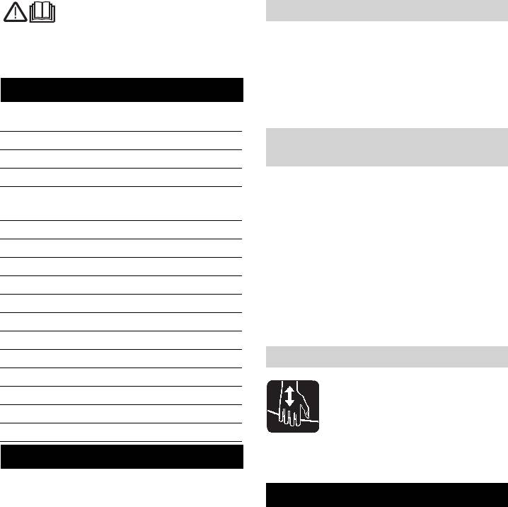
Technische Daten
BR BD
Leistung
Nennspannung V 24
Batteriekapazität Ah (5h) max. 180/205
Mittlere Leistungsaufnahme W 1900 1500
Fahrmotorleistung (Nennleistung) W 200
Saugmotorleistung W 500
Bürstmotorleistung W 2x 600 1x 800
Sicherungen
F1 (Hauptsicherung) A 125 150
F2 (Steuerung) A 3
Saugen
Saugleistung, Luftmenge l/s 22
Saugleistung, Unterdruck kPa 11,5
Reinigungsbürsten
Bürstendrehzahl 1/min 1350 180
Maße und Gewichte
Theoretische Flächenleistung m²/h 2475
Volumen Frisch-/Schmutzwassertank l 60/55
max. Wassertemperatur °C 60
Transportgewicht kg 235
Gesamtgewicht kg (295) 300*
Ermittelte Werte gemäß EN 60335-2-72
2
Schwingungsgesamtwert m/s
<2,5
2
Unsicherheit K m/s
0,2
Schalldruckpegel L
pA
dB(A) 72
Unsicherheit K
pA
dB(A) 1
Schallleistungspegel L
WA
+ Unsicherheit K
WA
dB(A) 91
* Package-Geräte
– 19
21DE

CE-Erklärung
Garantie
Hiermit erklären wir, dass die nachfolgend
In jedem Land gelten die von unserer zu-
bezeichnete Maschine aufgrund ihrer Kon-
ständigen Vertriebsgesellschaft herausge-
zipierung und Bauart sowie in der von uns
gebenen Garantiebedingungen. Etwaige
in Verkehr gebrachten Ausführung den ein-
Störungen an Ihrem Zubehör beseitigen wir
schlägigen grundlegenden Sicherheits-
innerhalb der Garantiefrist kostenlos, so-
und Gesundheitsanforderungen der EG-
fern ein Material- oder Herstellungsfehler
Richtlinien entspricht. Bei einer nicht mit
die Ursache sein sollte. Im Garantiefall
uns abgestimmten Änderung der Maschine
wenden Sie sich bitte mit Kaufbeleg an Ih-
verliert diese Erklärung ihre Gültigkeit.
ren Händler oder die nächste autorisierte
Kundendienststelle.
Produkt: Bodenreiniger
Typ: 1.384-xxx
Ersatzteile
Einschlägige EG-Richtlinien
2006/42/EG (+2009/127/EG)
– Es dürfen nur Zubehör und Ersatzteile
2004/108/EG
verwendet werden, die vom Hersteller
Angewandte harmonisierte Normen
freigegeben sind. Original-Zubehör und
EN 55014–1: 2006
Original-Ersatzteile bieten die Gewähr
EN 55014–2: 1997 + A1: 2001
dafür, dass das Gerät sicher und stö-
EN 60335–1
rungsfrei betrieben werden kann.
EN 60335–2–29
– Eine Auswahl der am häufigsten benö-
EN 60335–2–72
EN 61000–3–2: 2006 + A2: 2009
tigten Ersatzteile finden Sie am Ende
EN 61000–3–3: 2008
der Betriebsanleitung.
Angewandte nationale Normen
– Weitere Informationen über Ersatzteile
-
erhalten Sie unter www.kaercher.com
im Bereich Service.
Die Unterzeichnenden handeln im Auftrag
und mit Vollmacht der Geschäftsführung.
CEO
Head of Approbation
Dokumentationsbevollmächtigter:
S. Reiser
Alfred Kärcher GmbH & Co. KG
Alfred-Kärcher-Str. 28 - 40
71364 Winnenden (Germany)
Tel.: +49 7195 14-0
Fax: +49 7195 14-2212
Winnenden, 2010/07/14
22 DE
– 20
Please read and comply with
Safety Devices
these original instructions prior
English
to the initial operation of your appliance and
Safety devices serve to protect the user
store them for later use or subsequent own-
and must not be rendered inoperational or
ers.
their functions bypassed.
Emergency-stop button
Contents
To put all functions out of operation imme-
diately.
Safety instructions EN - 1
Function EN - 1
Symbols in the operating instruc-
Proper use EN - 2
tions
Environmental protection EN - 2
Danger
Operating and Functional El-
EN - 3
Immediate danger that can cause severe
ements
injury or even death.
Before Startup EN - 5
몇 Warning
Operation EN - 6
Possible hazardous situation that could
Shutting Down the Appliance EN - 10
lead to severe injury or even death.
Transport EN - 11
Caution
Storage EN - 11
Possible hazardous situation that could
Maintenance and care EN - 11
lead to mild injury to persons or damage to
property.
Faults EN - 15
Accessories EN - 16
Symbols on the machine
Technical specifications EN - 18
CE declaration EN - 19
Warranty EN - 19
Spare parts EN - 19
Risk of injury on account of being crushed.
Safety instructions
Hold the tank only in this area while tilting
downward.
Before using the appliance for the first time,
read and observe these operating instruc-
Function
tions and the accompanying brochure:
The scrubber vacuum is used for wet clean-
Safety information for brush cleaning units
ing or polishing of level floors.
and spray-extraction units, No. 5.956-251.
– It can be easily adjusted to suit the re-
The machine has been approved for use on
quired cleaning task by adjusting the
surfaces with gradients of up to 2%.
water quantity, the contact pressure of
While working at place with an upward/
the brushes and the waste water suc-
downward inclination between 2 - 10%, the
tion.
attachment set (ABS) for additional brake
– A working width of 550 mm and a ca-
2.640-376 must have been installed for
pacity of 60 l each of the fresh and 55 l
your own safety.
of the dirt water reservoirs enable an ef-
The appliance may only be operated
fective cleaning when the machine is to
when the hood and all lids are closed.
be used for a longer period of time.
During operations, the key switch
– The device is self-moving; the drive mo-
should not have been set to "O“. Press
tor is feed by four batteries.
emergency stop button in case of dan-
ger.
– 1
23EN

– The batteries can be charged using a
Environmental protection
charger connected to a 230 V socket.
– Depending on the package type, bat-
tery and charger are already integrated.
The packaging materials are
Note
recyclable. Please do not throw
packaging in the domestic
The appliance can be equipped with vari-
waste but pass it on for recy-
ous accessories depending on the cleaning
cling.
task.
Please request our catalogue or visit us on
Old units contain valuable recy-
the Internet at www.kaercher.com.
clable materials. Batteries, oil
and similar substances may
Proper use
not be released into the envi-
Use this appliance only as directed in these
ronment. Therefore please dis-
operating instructions.
pose of old units through
– The appliance may only be used for the
suitable collection systems.
cleaning of hard surfaces that are not
Notes about the ingredients (REACH)
sensitive to moisture and polishing op-
You will find current information about the
erations.
ingredients at:
– The appliance is not suited for the
http://www.karcher.de/de/unternehmen/
cleaning of frozen grounds (e.g. in cold
umweltschutz/REACH.htm
stores).
– The appliance may only be equipped
with original accessories and spare
parts.
– The appliance is not suited for the use
in potentially explosive environments.
– The machine should not be used to
suck in inflammable gases, undiluted
acids or solvents.
This includes petrol, thinning agents or
hot oil that can form an explosive mix-
ture when it comes in contact with
sucked air. Do not use acetone, undi-
luted acids and solvents as they are ag-
gressive towards the materials from
which the appliance is made.
– The machine has been approved for
use on surfaces with gradients of up to
2%.
While working at place with an upward/
downward inclination between 2 - 10%,
the attachment set (ABS) for additional
brake 2.640-376.0 must have been in-
stalled for your own safety.
24 EN
– 2
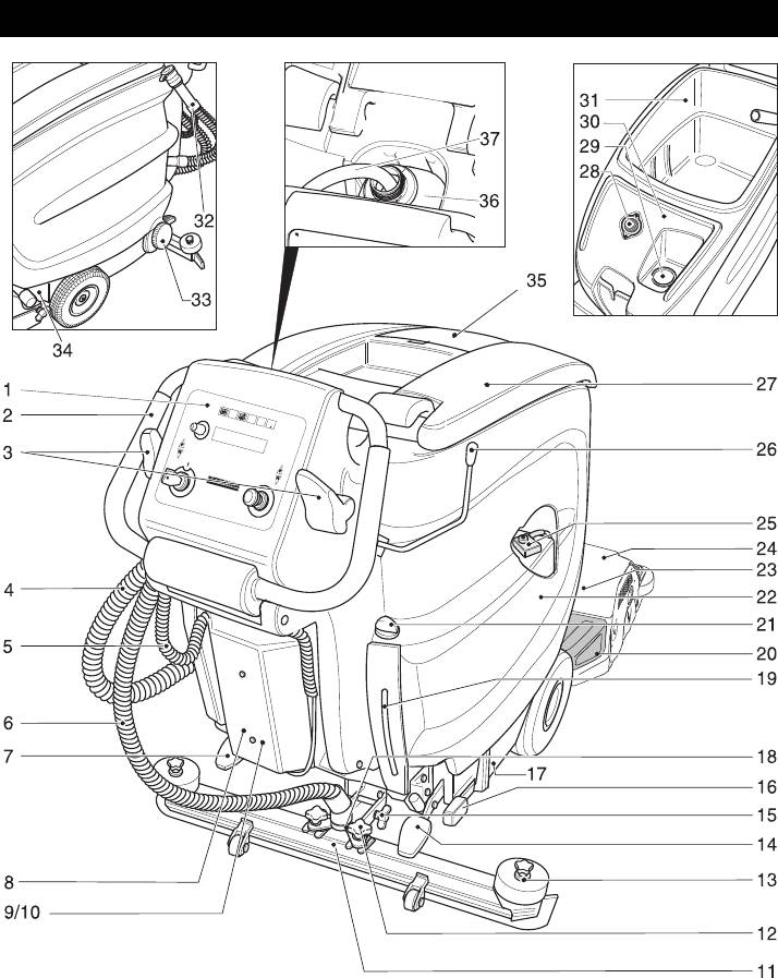
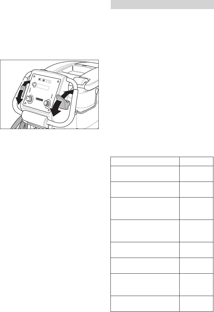
Operating and Functional Elements
1 Operator console
7 Pedal for operating the parking brake
2 Push handle
(Optional)
3 Driving lever
8 Charger (only Pack model)
4 Dirt water discharge hose
9 Electronics and fuses
5 Connecting cable for charger (only
10 Screws of electronics cabinet cover
Pack model)
11 Vacuum bar *
6 Suction hose
– 3
25EN
12 Cross handles for fastening the vacuum
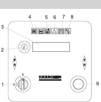
Operator console
bar
13 Cross-handles for replacing the vacu-
um lips
14 Pedal for raising/ lowering the cleaning
head
15 Wing nuts for tilting the vacuum bar
16 Level for adjusting the brush contact
pressure
17 Nameplate
18 Vacuum bar suspension
19 Fresh water level display
20 Waste container (only BR)
21 Water quantity regulator
22 Battery (only package model)
23 Brush rollers (BR model) Disk brushes
1 Key switch
(BD model) *
2 Info button
24 Cleaning head *
3 Display for
25 Main fuse F1
– Battery status
26 Vacuum bar lowering lever
- Cleaning speed
27 Cover dirt water reservoir
- Brush speed
28 Fluff filter
- WDB function
29 Filling nozzle for fresh water tank
– Operating hours
30 Fresh water tank
– Speed
31 Dirt water reservoir
- Detergent dosing (only Dose model)
32 Dosing equipment for dirt water
– Manufacturer
33 Fresh water tank lock
– Programme version
34 Locking the tank
4 Indicator lamp (red), lights up when the
35 Lid of air channel (installed firmly; can
batteries are discharged
only be removed by an expert)
5 Indicator lamp (red), lights up when the
36 2.5 l detergent bottle *
detergent bottle is empty (only Dose
37 Suction hose for detergent (only Dose
model)
model)
6 Indicator lamp (red), lights up when the
brushes are overloaded
* not included in the delivery
7 Indicator lamp (green), lights up when
the water is added
8 Indicator lamp (green), lights up when
vacuum is on
9 Emergency-stop button (turn to re-
lease)
26 EN
– 4
Drive the machine directly to the charg-
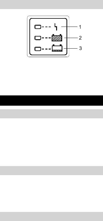
Charger (only Pack model)
ing station; avoid any steep gradients in
the process.
Note
While using other batteries (for e.g. batter-
ies from other manufacturers) the total dis-
charge protection level must be reset by the
Kärcher aftersales service according to the
respective battery.
1 red LED lights up = Problem with charg-
Danger
er/ battery; inform Customer Service
Risk of electric shock. Observe supply net-
2 green LED lights up = batteries are full
work and fuse protection - see "Charger".
3 yellow LED lights up = batteries are be-
Only use the charger in dry rooms with suf-
ing charged
ficient ventilation!
Before Startup
Note
Average charging time is approx. 10 -15
Installing the Brushes
hours.
The recommended chargers (matching the
BD model
batteries used) are regulated electronically
The sweep brushes must be installed be-
and will automatically switch off the charg-
fore the initial operation (see "Maintenance
ing process.
work").
All functions of the machine are automati-
BR model
cally interrupted during the charging proc-
The brushes are mounted.
ess.
Install batteries
Charging procedure for Pack model
Insert the plug of the connecting cable
The "Pack" model contains built-in batter-
into the socket.
ies.
With the other models, the batteries must
Charging process without integrated
be installed (see "Care and Maintenance /
charger
Installing and Connecting Batteries").
Empty the dirt and fresh water tank.
Loosen the tank lock and tilt the tank
Charging battery
upwards.
Danger
Remove battery plug and join it to the
Danger of explosion. Wet batteries can
charging cable.
only be charged with opened hood.
Connect the charger to the mains and
turn it on.
Note
The device is equipped with a safety mech-
Low maintenance batteries (wet batter-
anism to prevent total discharge, i.e. when
ies)
the permissible minimum capacity is
Add distilled water one hour before the
reached, then the brush motors and the tur-
charging process comes to an end; fol-
bine are switched off. In such a case, the
low the correct acid level. There are
battery status display on the control con-
corresponding indicators on the battery.
sole glows red. From this moment onwards,
몇 Warning
only driving mechanism is possible.
Danger of causticization!
– 5
27EN
– Adding water to the battery in its dis-
Place long lateral boards of the packag-
charged state can cause the acid to
ing as a ramp next to the pallet.
leak.
– Use safety glasses while handling bat-
tery acid and follow the safety instruc-
tions to avoid personal injury or damage
to clothes.
– Should the acid spray on to the skin or
clothes, rinse immediately with lots of
water.
Caution
Risk of damage!
– Use only distilled or desalinated water
(EN 50272-T3) for filling the battery.
Fix the ramp on the pallet with nails.
– Do not add any substances (so-called
Place short boards as a support under-
performance improving agents), else
neath the ramp.
warranty claims will not be entertained.
Remove the wooden bars in front of the
몇 Warning
wheels.
Only use maintenance-free batteries while
Lift cleaning head with pedal and re-
replacing batteries in package appliances.
move the carton packing.
Set main switch to “1”.
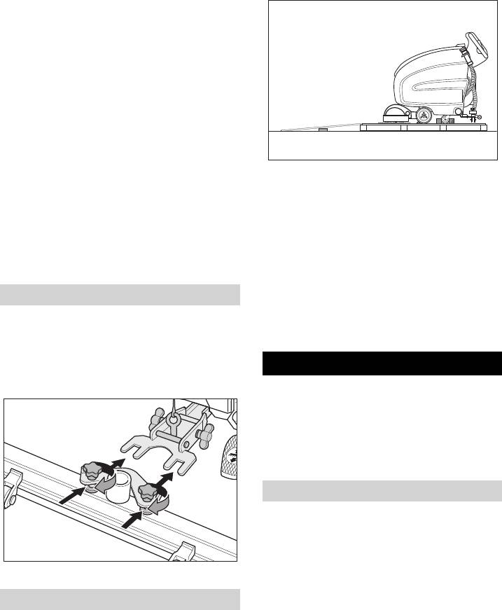
Installing the Vacuum Bar
Press the driving lever and slowly move
Insert the vacuum bar into the vacuum
the machine down from the ramp.
bar suspension in such a manner that
Set main switch to “0”.
the profiled sheet is positioned above
the suspension.
Operation
Tighten the cross-handles.
Danger
Risk of injury. Press on the foot pedal only
with one foot. The other foot must firmly be
placed on the floor. Press emergency-stop
switch to immediately switch off all func-
tions of the machine.
Driving
Caution
Risk of damage. The vacuum bar must be
liften to move in reverse direction.
Note
Insert the suction hose.
The machine is designed in such a way that
Unloading
the brush head protrudes on the right. This
helps in working in a proper way even close
Danger
to the edges.
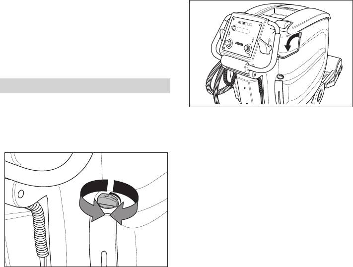
Risk of injury. Press emergency-stop
Release emergency-stop button by
switch to immediately switch off all func-
turning.
tions of the machine.
Insert key in key switch at the operator
Insert batteries and connect (see "Be-
console and turn to "1".
fore Start-up").
28 EN
– 6
Release parking brake (optional); move
Filling in detergents
the pedal downward and turn to the left.
Then let the pedal move upwards.
Fresh water
Drive the machine.
Open cover.
Forwards:
Fill fresh water (maximum 60 °C) until
Press the driving lever to the front.
the lower edge of the filling nozzle.
Backward:
Close the lid.
Press the driving lever to the rear.
Detergent
몇 Warning
Risk of damage. Only use the recommend-
ed detergents. With respect to different de-
tergents the operator bears the increased
risk regarding the operational safety and
danger of accident.
Only use detergents that are free from sol-
vents, hydrochloric acid and hydrofluoric
acid.
Follow the safety instructions for using de-
tergents.
Note
Note
The machine moves only when the driving
Do not use highly foaming detergents.
lever is moved by 15°.
Recommended detergents:
Set the working speed.
Application Detergent
– Forwards:
Turn the info button clockwise until
Routine cleaning of all wa-
RM 745
"CleanSpd Fwd=xxx%" is displayed.
ter resistant floors
RM 746
– Backward:
Routine cleaning of glossy
RM 755 es
Turn the info button clockwise until
surfaces (e.g. granite)
"CleanSpd Rev=xxx%" is displayed.
Routine cleaning and ba-
RM 69 ASF
sic cleaning of industrial
Note
floors
If the info button is not pressed for 10 sec-
Routine cleaning and ba-
RM 753
onds the display toggles to the battery dis-
sic cleaning of fine stone-
play.
ware tiles
– Shortly press the info button - display
Routine cleaning of tiles in
RM 751
blinks.
sanitary areas
– Set the speed by turning the info button.
The value can be set in increments of
Cleaning and disinfection
RM 732
10% between 30% and 100%.
in sanitary areas
– Press the info button to confirm the set
Removal of coating from
RM 752
value.
all alkali-resistant floors
Stop the machine: Release driving le-
(e.g. PVC)
ver.
Removal of coating from li-
RM 754
noleum floors
– 7
29EN
Model with dosing equipment "Dose"
Adjust detergent dose
Detergent is added to the fresh water on
Turn the info button clockwise until "RM
the way to the cleaning head with the help
- Dosierung“ or "RM - Dosing" is dis-
of a dosaging device.
played.
Shortly press the info button - display
Note
blinks.
The metering device can be used to add
Adjust the detergent dose by turning the
3% of detergent at maximum. In case of a
info button (0.5% to 3%).
higher dose the detergent must be poured
Press the info button to confirm the set
into the fresh water tank.
value.
Place the bottle with the detergent in
Note
the holder behind the operator console.
If no water is to be added to the detergent,
Close the bottle lid.
then the dosing must be set to 0%.
Insert the suction hose of the dosaging
equipment into the bottle.
Lower the vacuum bar
Turn the lever downwards; the vacuum
Note
bar is lowered and the suction turbine is
If the fresh water tank is empty, then the
switched on.
function of adding detergent gets deactivat-
ed. The cleaning head continues to work
without the addition of any liquid. Detergent
addition is also stopped when the detergent
can is empty.
Models without dosing equipment Dose
Add the detergent to the fresh water
reservoir.
Settings
Setting the water quantity
Adjust the water quantity using the reg-
Note
ulating button according to the dirt on
For cleaning tiled floors, set the straight
the floor covering.
vacuum bar in such a way that cleaning is
done at right angles to the joints.
The inclined position and the inclination of
the vacuum bar can be adjusted to achieve
better suction results (see "Setting the Vac-
uum Bar").
Setting the brush speed
Turn the info button clockwise until
"FACT" is displayed.
Shortly press the info button - display
blinks.
Set the brush speed by turning the info
button.
Note
– "...Power" - high speed (100%).
Carry out the initial cleaning attempts with
– "...Whisper" - medium speed (60%).
little quantities of water. Increase water
– "...Fine" - low speed (40%).
quantity step-by-step until the desired
Press the info button to confirm the set
cleaning result is achieved.
value.
30 EN
– 8
requirements until the desired polishing re-
Switching on the cleaning head
sult is achieved.
Caution
Risk of damage to the floor covering. Do
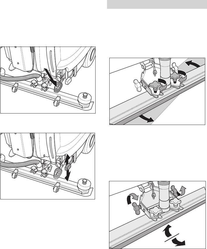
Setting the Vacuum Bar
not operate the appliance on the spot.
Oblique position
Press the pedal downwards; move it to
To improve the vacuuming result on tiled
the left and release it upward. The
floors the vacuum bar can be turned to an
cleaning head is lowered and the brush
oblique position of up to 5°.
motor starts automatically.
Loosen cross-handles.
Turn the vacuum bar.
Adjust brush contact pressure at the le-
ver.
Tighten the cross-handles.
Inclination
If the vacuum result is unsatisfactory the in-
clination of the straight vacuum bar can be
modified.
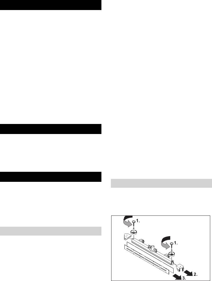
Release the wing nuts.
Tilt the vacuum bar.
Note
Carry out the initial cleaning attempts with
less contact pressure. Increase contact
pressure step-by-step until the desired
cleaning result is achieved. A correct set-
ting of the contact pressure reduces power
consumption and the wear and tear of the
brushes.
Tighten the wing nuts.
The brush motors come to a halt when the
machine stops and when there is overload.
Caution
Floors can get damaged on account of too
high contact pressure. Carry out the initial
polishing attempts with less contact pres-
sure. Increase the contact pressure as per
– 9
31EN

Set the key switch at the operator con-
Turning on/off WDB
sole to "0" and remove the key.
This function is required for operating the
Charge battery, if required.
spray suction attachment (accessory).
Drain off dirt water
Turn the info button clockwise until
"WDB-Funktion" or "WDB-Function" is
몇 Warning
displayed.
Please observe the local provisions regard-
Shortly press the info button.
ing the wastewater treatment.
Select "ON" or "OFF" by turning the info
Take the water discharge hose from the
button.
support and lower above a suited col-
Press the info button to confirm the set
lection device.
value.
Stand-by
If the operational break exceeds 30 min-
utes, the machine goes into stand-by
mode. To restart the machine, turn the key
switch briefly to "0" and then turn it again to
"1".
Shutting Down the Appliance
Close the regulatory button for setting
the water quantity.
Crush or bend the dosing equipment.
Release driving lever.
Open the lid of the dosing equipment.
Lift the cleaning head.
Drain off the dirt water - regulate the wa-
Briefly drive forward and suck of the re-
ter quantity by pressing or bending.
maining water.
Rinse the dirt water tank with clear wa-
Raise the vacuum bar.
ter.
The suction turbine will continue to run
Drain off clean water
for 5 more seconds to suck off residual
water from the vacuum bar and the vac-
uum hose.
Apply parking brake (optional). Press
the pedal downwards and move it to the
right to lock it.
Loosen the lid for emptying the fresh
water - do not remove it fully. Drain wa-
ter.
Remove the lid with washer fully to
rinse off the fresh water tank.
32 EN
– 10
Check the fluff filter, clean if required
Transport
Only BR model: Remove bulk waste
Danger
container and empty it.
Clean the vacuum lips and the wiping
Risk of injury! When loading or unloading
lips, check for wear and replace if re-
the machine, it may only be operated on
quired.
gradients of max. 10%. Drive slowly.
Check the brushes for wear, replace if
Caution
required.
Risk of injury and damage! Observe the
weight of the appliance when you transport
Monthly
it.
Check battery pole for oxidation; brush
Raise the cleaning head to avoid dam-
it if required and lubricate it using pole
age to the brushes.
grease. Ensure that the connection ca-
Remove the brush to avoid damage to
ble sits firmly.
the brushes.
Check the function of the immobilizing
Apply parking brake (optional).
brake (optional).
When transporting in vehicles, secure
Clean the seals between dirt water res-
the appliance according to the guide-
ervoir and cover and check for tight-
lines from slipping and tipping over.
ness, replace if required.
Check the acid density of the cells if the
Storage
batteries are not maintenance-free bat-
teries.
Caution
Clean the brush tunnel (only BR mod-
Risk of injury and damage! Note the weight
el).
of the appliance in case of storage.
This appliance must only be stored in inte-
Yearly
rior rooms.
Have the prescribed inspection carried
out by the customer service.
Maintenance and care
Maintenance Works
Danger
Risk of injury! Before carrying out any tasks
Replace or turn vacuum lips
on the machine, set the main key to "0" and
Remove the vacuum bar.
remove key and plug of the charger.
Unscrew the star grips.
Drain and dispose of the dirt water and
the residual fresh water.
Maintenance schedule
After each operation
Caution
Risk of damage. Do not wash down the ap-
pliance with water and do not use aggres-
sive detergents.
Drain off dirt water.
Rinse the dirt water tank with clear wa-
Remove the plastic parts.
ter.
Remove the vacuum lips.
Clean the outside of the appliance with
Insert new vacuum lips.
a damp cloth which has been soaked in
Insert the plastic parts.
mild detergent.
Screw in and tighten the star grips.
– 11
33EN
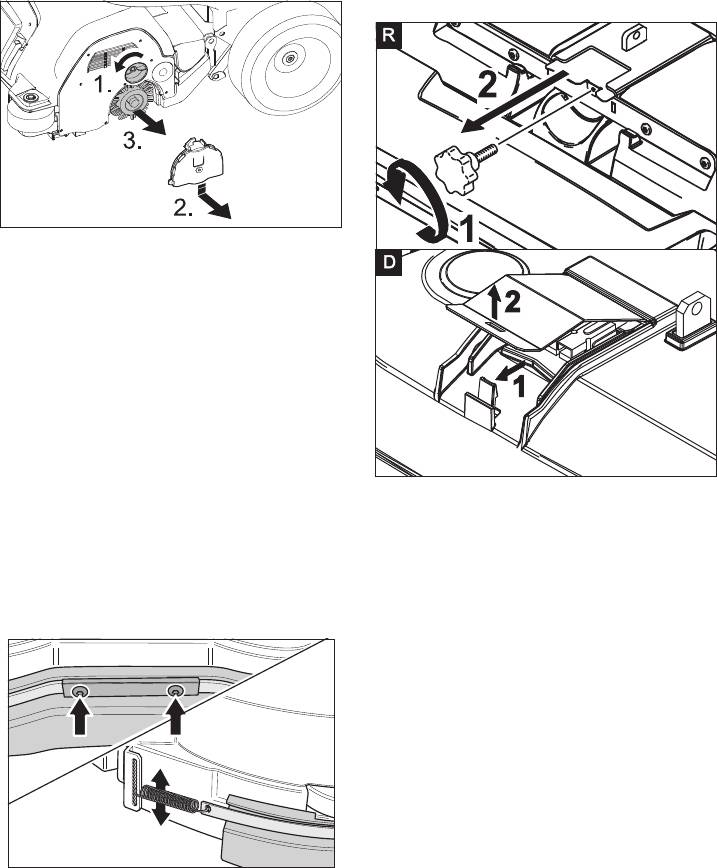
Replacing the brush rollers
Install cleaning head
Lift the cleaning head.
Release the screw for locking the tank
and swing up the tank.
Loosen the lock of the wiper flap.
Push the bearing lid down and remove.
Pull out the brush roller.
Insert a new brush roller.
Reassemble the bearing lid in the re-
verse sequence.
Repeat process on the opposite side.
Replacing the Disk Brushes
Lift the cleaning head.
Press the pedal for changing the brush-
es downward beyond its resistance.
R cleaning head: Unscrew the star han-
Pull the disc brush out of the side below
dle and remove the lid.
the cleaning head.
D cleaning head: Remove the lid of the
Hold the new disc brush under the
cleaning head.
cleaning head, push upward and lock.
Place the cleaning head halfway in front
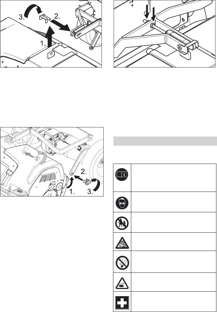
Mount splash guard
of the appliance.
Connect the power cord of the cleaning
head to the appliance (same colours
must meet).
R cleaning head: Slide the lid in and
tighten the screw.
D cleaning head: Replace the lid and
lock it.
Connect the hose couplers on the
cleaning head to the hose on the appli-
ance.
Loosen both screws.
Move both the drawing springs in the
desired position.
Align the splash guard.
Tighten both the screws.
34 EN
– 12
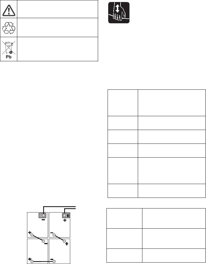
Insert the tab into the middle of the
Loosen the nuts of the adjustment
cleaning head, between the fork of the
screw and align the cleaning head in
lever.
such a way that the brush rollers touch
Position the lever on the pedal for rais-
the floor in an even manner.
ing/lowering so that the borings in the
Then tighten the nuts of the adjustment
lever and the cleaning head align.
screw.
Insert the stop pin through the bushings
Dismantling the cleaning head
and swivel the locking plate downward.
The removal will take place in the opposite
order of the installation.
Batteries
Please observe the following warning notes
when handling batteries:
Observe the directions on the bat-
tery, in the instructions for use
and in the vehicle operating in-
structions
Wear eye protection
Align the pushing rod in the handle at
the cleaning head.
Insert the stop pin from the right through
Keep children away from acid and
the bushings and swivel the locking
batteries
plate downward.
Repeat process on the pushing rod on
Danger of explosion
the opposite side.
Note
Fire, sparks, naked flames and
Both the pins at the pushing rods are
smoking must be strictly avoided
pushed in from the same side through the
bushings (not in opposite directions).
Danger of chemical burns
First aid
– 13
35EN
Warning note
Disposal
몇 Warning
Risk of injury on account of being crushed.
Do not throw the battery into the
Hold the tank only in this area while tilting
regular waste
downward.
Tilt the water tank towards the front.
몇 Warning
Danger
Charge the battery before commissioning
Danger of explosion. Do not put tools or
the machine.
similar on the battery, i.e. on the terminal
Recommended batteries
poles and cell connectors.
Risk of injury. Ensure that wounds never
Manufac-
Description
come into contact with lead. Always clean
turer,
your hands after having worked with batter-
Kärcher or-
ies.
der no.
Insert batteries and connect
DETA
24 V GtV 180 DTP, mainte-
The BAT package model contains built-in
6.654-130
nance-free, 180 Ah, 4 x 6 V
batteries.
DETA 24 V PzS 170 (5), low main-
Loosen the tank lock and tilt the tank
tenance, 170 Ah, 4 x 6 V
upwards.
DETA
24 V GiV 160 DT, mainte-
Place the batteries close to each other
6.654-089
nance-free, 160 Ah, 4 x 6 V
towards the cleaning head in the tray
SONNEN-
020 8517 405, low mainte-
and fasten them using the fastening
SCHEIN
nance, 175 Ah, 4 x 6 V
bracket behind the batteries.
(SUN-
Grease the battery poles using pole
SHINE)
grease.
TROJAN T-145, low maintenance,
Connect poles with the enclosed con-
205 Ah, 4 x 6 V
necting cables.
Recommended chargers
Manufactur-
Description
er, Kärcher
order no.
KÄRCHER
Charger 2425 for low
6.654-072.0
maintenance batteries, 24
V
KÄRCHER
Charger 2425 for mainte-
6.654-078.0
nance-free batteries, 24 V
A supply cable/ adapter 6.648-582 is re-
quired for both the chargers.
몇 Warning
Batteries and chargers are available in spe-
Pay attention to correct poles.
cialised stores.
Connect the connection cable to the
free battery poles (+) and (-).
36 EN
– 14

Removing the batteries
Frost protection
Set the key switch at the operator con-
In case of danger of frost:
sole to "0" and remove the key.
Empty the fresh and dirt water reser-
Loosen the tank lock and tilt the tank
voirs.
upwards.
Store the appliance in a frost-protected
Clamp off the minus pole of the battery.
room.
Clamp off the remaining cables from the
Faults
battery.
Unscrew the fastening angle.
Danger
Remove the batteries.
Risk of injury! Before carrying out any tasks
Dispose of the used batteries according
on the machine, set the main key to "0" and
to the local provisions.
remove key and plug of the charger.
Drain and dispose of the dirt water and
Maintenance contract
the residual fresh water.
To ensure a reliable operation of the appli-
In case of faults that cannot be remedied
ance maintenance contracts can be con-
using the table below please contact the
cluded with the competent Kärcher sales
customer service.
office.
Fault Remedy
Appliance cannot be
Stand-by, turn key switch to "0", then set it back to "1".
started
Check fuse F2*, replace if required. *
Check battery; charge it if required.
Machine does not
Check whether the immobilizing brake (optional) has been ap-
move
plied.
Insufficient water
Check fresh water level, refill tank if necessary.
quantity
Check hoses for blockages; clean if required.
Insufficient vacuum
Clean the seals between dirt water reservoir and cover and
performance
check for tightness, replace if required.
Clean the fluff filter.
Clean the vacuum lips on the vacuum bar, replace if required
Check suction hose for blockages; clean if required.
Check the suction hose for tightness; replace if required.
Check if the cover on the dirt water discharge hose is closed
Check the setting of the vacuum bar.
Insufficient cleaning
Set/ adjust contact pressure.
result
Check the brushes for wear, replace if required.
Brushes do not turn Reduce contact pressure.
Check if foreign matters block the brushes; remove foreign mat-
ter if required.
If over-current switch in the electronics system has been trig-
gered, turn key switch to "0", then set it back to "1".
* Remove screws of the electronics system and tilt the electronics cover with charger
downwards
– 15
37EN

Accessories
Accessories BR...
Description Part no.:
Part no.:
Description
Working
Working
width 550
width 650
mm
mm
Piece
Machine requires piece
Cleaning head 2.763-
2.763-004.0 1 1
002.0
Brush roller, red
6.906-
6.906-935.0 Also for regular cleaning of
12
(medium, stand-
934.0
heavily dirtied floors.
ard)
Brush roller, white
6.906-
6.906-981.0 For polishing and cleaning
12
(soft)
977.0
sensitive floors.
Brush roller, or-
6.906-
6.906-982.0 For scrubbing structured
12
ange (high/ low)
978.0
floors (safety tiles, etc.).
Brush roller, green
6.906-
6.906-983.0 For thoroughly cleaning
12
(grit)
979.0
heavily dirtied floors and for
removing the coating (for
Brush roller, grey
6.906-
6.906-984.0 1 2
e.g. of wax, acrylate).
(1 mm grit)
980.0
Pad roller shaft 4.762-
4.762-433.0 For intake of roller pads. 1 2
432.0
Roller pad, white
6.369-389.0 For cleaning and polishing
20 60 80
(very soft)
sensitive floorings.
Roller pad, yellow
6.369-454.0 For polishing floors. 20 6080
(soft)
Roller pad, red
6.369-456.0 For cleaning slightly dirtied
20 60 80
(medium)
floors.
Roller pad, green
6.369-455.0 For cleaning normal to
20 6080
(hard)
heavily dirtied floors.
38 EN
– 16

Accessories BD...
Description Part no.:
Part no.:
Description
Working
Working
width 550
width 650
mm
mm
Piece
Machine requires piece
Cleaning head 2.763-001.0 2.763-003.0 1 1
Disk brush, nat-
4.905-016.0 4.905-012.0 For polishing floors. 1 2
ural (white)
Disk brush, red
4.905-014.0 4.905-010.0 For cleaning slightly dirtied or
12
(medium, stand-
sensitive floors.
ard)
Disk brush,
4.905-017.0 4.905-013.0 For cleaning heavily dirtied
12
black (hard)
floors.
Accessories BR.../BD...
Description Part no.: Description Piece Machine
requires
piece
Rubber lip, blue 6.273-214.0 Standard pair 1 pair
Rubber lip, brown 6.273-208.0 oil-resistant pair 1 pair
Rubber lip, brown 6.273-205.0 Non-scarring pair 1 pair
Vacuum bar,
4.777-302.0 Standard 1 1
straight
Vacuum bar, bent 4.777-312.0 Standard 1 1
– 17
39EN

Technical specifications
BR BD
Power
Nominal voltage V 24
Battery capacity Ah (5h) max. 180/205
Average power consumption W 1900 1500
Drive motor output (rated output) W 200
Suction engine output W 500
Brush engine output W 2x 600 1x 800
Fuses
F1 (main fuse) A 125 150
F2 (control) A 3
Vacuuming
Cleaning power, air quantity l/s 22
Cleaning power, negative pressure kPa 11,5
Cleaning brushes
Brush speed 1/min 1350 180
Dimensions and weights
Theoretical surface cleaning performance m²/h 2475
Fresh/dirt water reservoir volume l 60/55
Max. water temperature °C 60
Transport weight kg 235
Total weight kg (295) 300*
Values determined as per EN 60335-2-72
2
Total oscillation value m/s
<2,5
2
Uncertainty K m/s
0,2
Sound pressure level L
pA
dB(A) 72
Uncertainty K
pA
dB(A) 1
Sound power level L
WA
+ Uncertainty K
WA
dB(A) 91
* Package appliances
40 EN
– 18


