Karcher Balayeuse KM 120-150 R D – страница 2
Инструкция к Воздушной Завесе Karcher Balayeuse KM 120-150 R D

Please read and comply with
Maintenance and care . . . . . EN . 10
dling the appliance or have proven
these original instructions prior
qualification and expertise in operating
General notes . . . . . . . .
EN
. 10
to the initial operation of your appliance and
the appliance or have been explicitly
Cleaning the inside of the
store them for later use or subsequent own-
assigned the task of handling the appli-
machine . . . . . . . . . . . . . EN
. 10
ers.
ance.
External cleaning of the ap-
Before first start-up it is definitely neces-
pliance . . . . . . . . . . . . . . EN
. 10
– The appliance must not be operated by
sary to read the safety indications no.
Maintenance intervals . .
EN
. 10
children, young persons or persons
5.956-250!
who have not been instructed accord-
Maintenance Works . . . .
EN
. .11
ingly.
Troubleshooting . . . . . . . . . . EN . 16
Contents
– It is strictly prohibited to take co-pas-
Technical specifications . . . . EN . 17
sengers.
Accessories . . . . . . . . . . . . . EN . 18
Appliance description . . . . . EN . . . 1
– Ride-on appliances may only be started
Installation set suction hose
EN
. 18
Safety instructions . . . . . . . EN . . . 1
after the operator has occupied the driv-
EC Declaration of Conformity EN . 18
General notes . . . . . . . .
EN
. . . 1
er's seat.
Warranty . . . . . . . . . . . . . . . EN . 18
Symbols on the machine
Please remove the ignition key, when
EN
. . . 2
not in use, to avoid unauthorised use of
Symbols in the operating in-
structions. . . . . . . . . . . . EN
. . . 2
Appliance description
the appliance.
Safety Guidelines for liqui-
Never leave the machine unattended
– KM 120/150 R G = Petrol engine
fied gas vehicles (only KM
so long as the engine is running. The
– KM 120/150 R D = diesel engine
120/150 R LPG) . . . . . . EN
. . . 2
operator may leave the appliance only
– KM 120/150 R LPG = gas engine
Function . . . . . . . . . . . . . . . EN . . . 3
when the engine has come to a stand-
Proper use . . . . . . . . . . . . . EN . . . 3
still, the appliance has been protected
Suitable surfaces. . . . . .
EN
. . . 3
Safety instructions
against accidental movement, if neces-
sary, by applying the immobilization
Environmental protection . . EN . . . 3
– The machine (without driver cabin) has
brake and the ignition key has been re-
Operating and Functional Ele-
been approved for use on surfaces with
ments . . . . . . . . . . . . . . . . . EN . . . 4
moved.
gradients of up to 18%.
Machines without driver cab-
Appliances with combustion engine
– The machine (with driver cabin) has
in . . . . . . . . . . . . . . . . . . EN
. . . 4
been approved for use on surfaces with
Danger
Machines with driver cabin
EN
. . . 4
gradients of up to 10%.
Risk of injury!
Colour coding . . . . . . . .
EN
. . . 4
– Do not close the exhaust.
General notes
Opening/closing and secur-
– Do not bend over the exhaust or touch
ing cover . . . . . . . . . . . . EN
. . . 5
Your sales outlet should be informed about
it (risk of burns).
Operator console. . . . . .
EN
. . . 6
any transit damage noted when unpacking
– Do not touch the drive motor (risk of
Before Startup. . . . . . . . . . . EN . . . 7
the product.
burns).
Unloading . . . . . . . . . . .
EN
. . . 7
– Warning and information plates on the
– Only KM 120/150 R LPG: Ensure that
machine provide important directions
Moving sweeper without en-
there is adequate ventilation or provi-
gaging self-propulsion. . EN
. . . 7
for safe operation.
sion for diverting the exhaust gas while
Moving sweeper by engag-
– In addition to the information contained
operating the appliance in closed
ing self-propulsion. . . . . EN
. . . 7
in the operating instructions, all statuto-
rooms (risk of poisoning).
Start up . . . . . . . . . . . . . . . . EN . . . 7
ry safety and accident prevention regu-
– Exhaust gases are poisonous and haz-
General notes . . . . . . . .
EN
. . . 7
lations must be observed.
ardous to health, do not inhale them.
Refuelling (only KM 120/150
Drive mode
– The engine requires approx. 3-4 sec-
R G and R D) . . . . . . . . EN
. . . 7
Danger
onds to come to a standstill once it has
Connect/ change gas cylin-
been switched off. During this time, stay
Risk of injury!
der (only KM 120/150 R
well clear of the working area.
LPG) . . . . . . . . . . . . . . . EN
. . . 7
Danger of tipping if gradient is too high.
Inspection and maintenance
– Drive up the slopes only with max. 18%
Machines with driver cabin
work. . . . . . . . . . . . . . . . EN
. . . 8
gradient (without driver cabin) or 10%
Note
Operation . . . . . . . . . . . . . . EN . . . 8
(with driver cabin).
The driver cabin only provides protection
Adjusting driver's seat . .
EN
. . . 8
Danger of tipping when driving round
against weather; it is not a safety roof or a
bends at high speed.
Adjusting the external mirror
lock against overrolling!
(only KM 120/150 without
– Drive slowly when cornering.
Danger
driver cabin) . . . . . . . . . EN
. . . 8
Danger of tipping on unstable ground.
The plastic sheet doors of the driver cabin
Switching on/off the wipers
– Only use the machine on sound surfac-
(only KM 120/150 without
have ventilation slots. Always leave these
es.
driver cabin) . . . . . . . . . EN
. . . 8
open to ensure adequate ventilation.
Danger of tipping with excessive sideways
Programme selection . .
EN
. . . 8
tilt.
Starting the machine . . .
Risk of hearing impair-
EN
. . . 8
– The gradient perpendicular to the direc-
ment. Always use
Drive the machine . . . . .
EN
. . . 8
tion of travel should not exceed 10%.
proper ear-protection
Sweeping mode . . . . . .
EN
. . . 8
– It is important to follow all safety instruc-
aids while working with
Emptying waste container
tions, rules and regulations applicable
EN
. . . 9
the appliance.
for driving motor vehicles.
Turn off the appliance . .
EN
. . . 9
– The operator must use the appliance
Shutdown . . . . . . . . . . . . . . EN . . . 9
properly. He must consider the local
Accessories and Spare Parts
Close fuel tap (only KM 120/
conditions and must pay attention to
. . 10
– Only use accessories and spare parts
150 R G and R D) . . . . . EN
third parties, in particular children, when
which have been approved by the man-
Close gas supply (only KM
. . 10
working with the appliance.
120/150 R LPG) . . . . . . EN
ufacturer. The exclusive use of original
– The appliance may only be used by per-
accessories and original spare parts
Transport. . . . . . . . . . . . . . . EN . . 10
sons who have been instructed in han-
Storing the device . . . . . . . . EN . . 10
- 1
21EN

ensures that the appliance can be oper-
– Ensure the correct positioning of the
Safety Guidelines for liquified gas
ated safely and trouble free.
cylinder with the "top" marking while
vehicles (only KM 120/150 R LPG)
– At the end of the operating instructions
connecting a full cylinder (the connec-
you will find a selected list of spare
Hauptverband der gewerblichen Beruf-
tion screw points vertically upward).
parts that are often required.
sgenossenschaften e.V. (HVBG / Germa-
Perform the replacement of the gas cylin-
– For additional information about spare
ny). Liquified gases (propellants) are
der carefully. During assembly and disas-
parts, please go to the Service section
butane and propane or a mixture of butane/
sembly, the gas outlet nozzle of the
at www.kaercher.com.
propane. They are available in special cyl-
cylinder valve must be sealed by means of
inders. The operating pressure of these
a cap nut that is tightened using a wrench.
Symbols on the machine
gases depends on the outside tempera-
– Discontinue the use of leaky gas cylin-
ture.
ders. Such cylinders are to be emptied
Risk of burns on ac-
Danger
by slowly letting out the gas in open
count of hot surfaces!
spaces by conforming to all safety reg-
Risk of explosion! Do not handle liquified
Allow the exhaust to
ulations and are to be indicated as
gas like petrol. Petrol evaporates slowly,
cool down sufficiently
leaky. Also inform the issuing company
liquified gas immediately turns into gas.
before starting work on
or its representative (the filling-station
The risk of gas spreading in the room and
the machine.
attendant) in writing about the damage
getting ignited is thus higher in case of liq-
to the cylinder while delivering or re-
uefied gas than in petrol.
Symbols in the operating instruc-
ceiving the cylinders.
Danger
tions
– Before connecting the gas cylinder,
Risk of injury! Use only liquefied gas cylin-
check that its connection neck is in a
DANGER
ders with propellant filled according to DIN
proper state.
Immediate danger that can cause severe
51622 of A or B quality, depending on the
– After connecting the cylinder, regularly
injury or even death.
surrounding temperature.
check that it is not leaky by using a
몇 WARNING
CAUTION
foaming agent.
Possible hazardous situation that could
Use of cooking gas is strictly prohibited. For
– Open the valves slowly. Do not use
lead to severe injury or even death.
the gas engine, use only liquid gas mix-
hammers to open and close the cylin-
tures of propane/ butane or their mixtures
CAUTION
ders.
where the mixing ratio lies between 90/10
Possible hazardous situation that could
– Use only dry fire extinguishers (with
to 30/70. On account of better cold start be-
lead to mild injury to persons or damage to
carbonic acid gas) in case of fire
haviour even at low outside sub-zero tem-
property.
caused by liquefied gases.
peratures (below 0° C / 32 °F) always
– The entire LPG unit must be continu-
prefer a mixture with a higher propane
ously checked to ensure that there are
share because evaporation takes place
no leaks and the unit is functioning
even at low temperatures.
properly. Using the vehicle with a leaky
Liabilities of the factory management
gas unit is strictly prohibited.
and the employee
– First close the cylinder valve before
– All persons handling liquid gases are li-
loosening the pipe or tube connection.
able to acquaint themselves with the
Unscrew and loosen the connection nut
special properties of the liquefied gases
of the gas cylinder slowly because oth-
for hazard-free handling of operations.
erwise the gas under pressure in the
The current documentation is always to
tube will flow out instantly.
be kept with the sweeper.
– If the gas is refilled from a larger tank,
Maintenance by expert
then ask the sales agent of the LPG
– Propellant-operated units are to be
about the important regulations to be
checked at regular intervals, at least
followed.
once a year, by an expert against leaks
Danger
(according to BGG 936) and ensure
Risk of injury!
that the unit is functioning properly.
– LPG in a liquid state can cause frost
– The inspection must be certified and
bites on bare skin.
documented. The inspection guidelines
– After disconnecting the cylinder, tighten
are § 33 and § 37 UVV (occupation ac-
the closing nut firmly on the connecting
cident prevention regulations) "Use of
threading of the cylinder.
liquid gas" (BGV D34).
– Use soap water or some such foaming
– General applicable regulations are the
agent to check whether the cylinder is
guidelines for inspecting vehicles
leaking. The use of open flames to illu-
whose engines are driven by liquefied
minate the LPG unit is strictly prohibit-
gases of the Federal Transportation
ed.
Minister.
– Follow the manufacturer's installation
Commissioning/Operations
specifications while changing individual
– Gas must always be drawn only from
parts of the LPG unit. Close all cylinder
one cylinder. Drawing gas from multiple
and locking valves while doing so.
cylinders simultaneously can cause liq-
– Regularly check the status of the elec-
uid gas from one cylinder flowing into
trical unit of the LPG vehicles . Sparks
the other. This causes the over-filled
can cause explosions if the gas-carry-
cylinder to be subjected to an unpermit-
ing parts of the unit are leaky.
ted excess pressure when the cylinder
– If a LPG-driven vehicle has been idling
valve is closed later (refer B.1 of these
for a long time, then first ventilate the
guidelines).
22 EN
- 2
setting room before commissioning the
use the appliance in hazardous loca-
Function
vehicle or its electrical unit.
tions.
– Immediately inform the trade associa-
– The following applies in general: Keep
tion and the concerned trade superviso-
highly-flammable substances away
ry authority about accidents with gas
from the appliance (danger of explo-
cylinders or LPG units. Store the dam-
sion/fire).
aged parts carefully until all investiga-
Suitable surfaces
tions have been completed.
– Asphalt
In the installation and storage rooms as
– Industrial floor
well as the workshops
– Propellants or LPG cylinders must al-
– Screed
ways be stored according to the regula-
– Concrete
tions of TRF 1996 (Technical
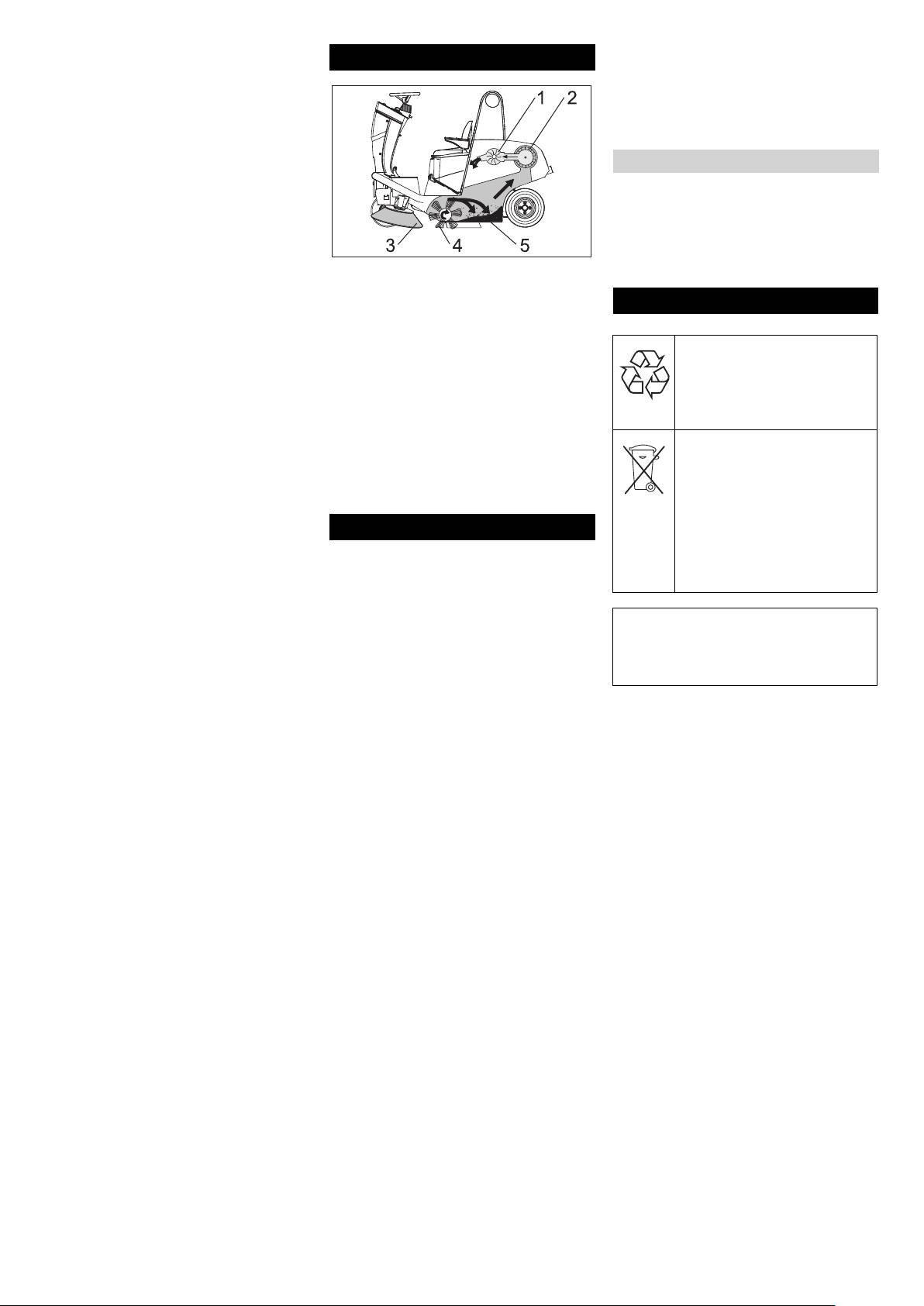
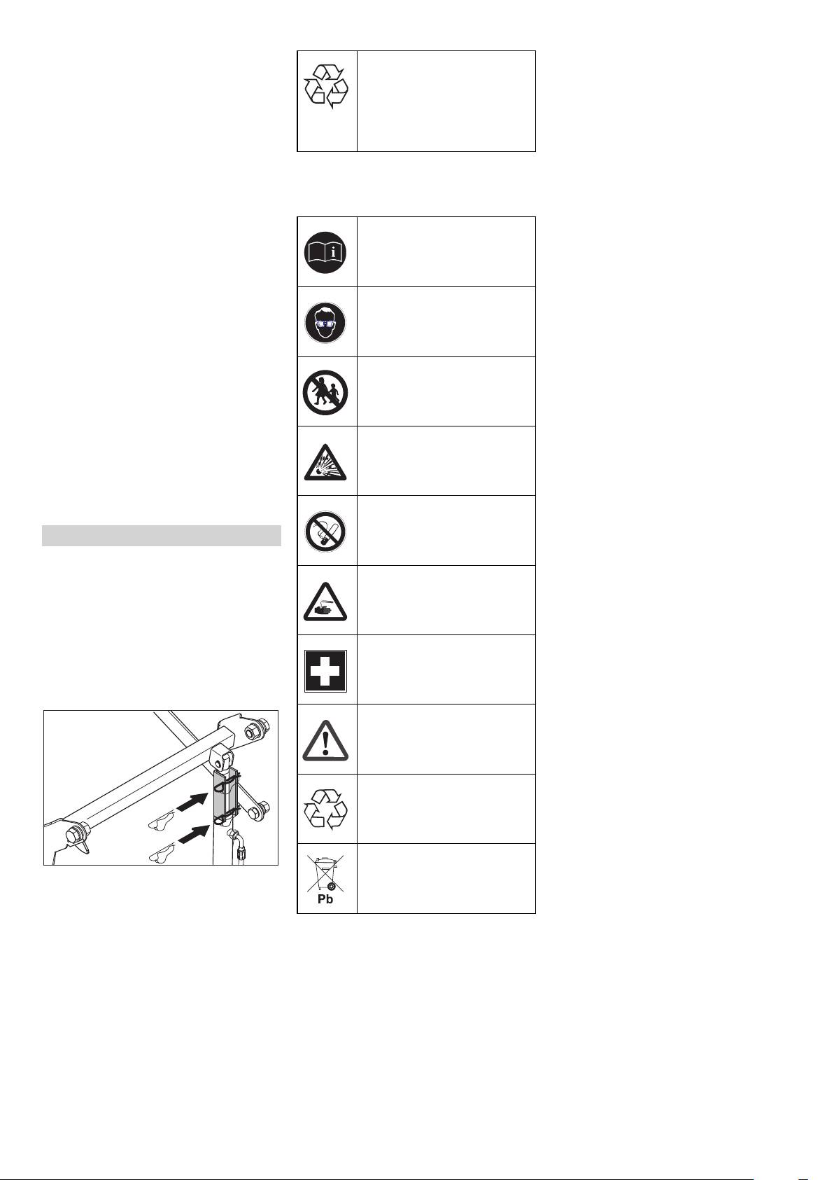
Figure 1
– Paving stones
Regulations for Liquid Gases, refer DA
The sweeper operates using the overthrow
to BGV D34, Appendix 4).
principle.
Environmental protection
– Always store the gas cylinders in a ver-
– The side brushes (3) clean the corners
tical position. Use of open flames and
and edges of the surface, moving dirt
smoking at the installation site of the
and debris into the path of the roller
The packaging material can be
cylinders and during repairs is strictly
brush.
recycled. Please do not throw
prohibited. Protect the stored cylinders
– The rotating roller brush (4) moves the
the packaging material into
against unauthorised access. Close all
dirt and debris directly into the waste
household waste; please send
empty cylinders properly.
container (5).
it for recycling.
– Close the cylinder and main locking
– The dust raised in the container is sep-
Old appliances contain valua-
valves immediately when you switch off
arated by the dust filter (2) and the fil-
ble materials that can be recy-
the vehicle.
tered clean air is drawn off by the
cled; these should be sent for
– Follow the regulations for garages and
suction fan (1).
recycling. Batteries, oil, and
the construction guidelines of the re-
similar substances must not
spective State about the location and
Proper use
enter the environment. Please
structure of the parking areas for LPG-
dispose of your old appliances
driven vehicles.
Use this appliance only as directed in these
using appropriate collection
– Gas cylinders are to be stored in sepa-
operating instructions.
systems.
rate rooms away from the parking areas
The machine with working equipment
(refer DA to BGV D34, Appendix 2).
must be checked to ensure that it is in
proper working order and is operating
Please do not release engine oil, fuel oil,
– The electrical hand-held lamps used in
safely prior to use. Otherwise, the appli-
diesel and petrol into the environment
the rooms are to be equipped with
ance must not be used.
Protect the ground and dispose of used
closed, sealed case and a strong pro-
oil in an environmentally-clean manner.
tection cover.
– This sweeper has been designed to
sweep dirt and debris from outdoor sur-
– Close all cylinder and main valves be-
Notes about the ingredients (REACH)
faces.
fore working in repair workshops and
You will find current information about the
protect the gas cylinders against effect
– Only KM 120/150 R LPG: This sweeper
ingredients at:
of external heat.
is also suitable for sweeping dirty floors
www.kaercher.com/REACH
in closed spaces provided the same are
– A responsible person must check that
ventilated adequately.
all valves, especially the cylinder
valves, are closed during operational
– The machine can only be used on pub-
breaks and before closing the factory.
lic highways with the StVZO extension
Do not carry out any jobs involving fire -
kit.
such as cutting and welding jobs - in the
– The machine is not suitable for vacuum-
vicinity of the gas cylinders. Do not
ing dust which endangers health.
store gas cylinders, not even empty
– The machine may not be modified.
ones, in the workshops.
– Never vacuum up explosive liquids,
– The parking and storage rooms and the
combustible gases or undiluted acids
repair workshops must be ventilated
and solvents. This includes petrol, paint
properly. Please note that liquefied gas-
thinner or heating oil which can gener-
es are heavier than atmospheric air.
ate explosive fumes or mixtures upon
They get collected on the floor, in re-
contact with the suction air. Acetone,
cesses and other holes in the floors and
undiluted acids and solvents must also
form a gas-air mixture that can lead to
be avoided as they can harm the mate-
explosions.
rials on the machine.
– Do not sweep/vacuum up any burning
or glowing objects.
– The machine is only suitable for use on
the types of surfaces specified in the
operating instructions.
– The machine may only be operated on
the surfaces approved by the company
or its authorised representatives.
– The machine may not be used or stored
in hazardous areas. It is not allowed to
- 3
23EN
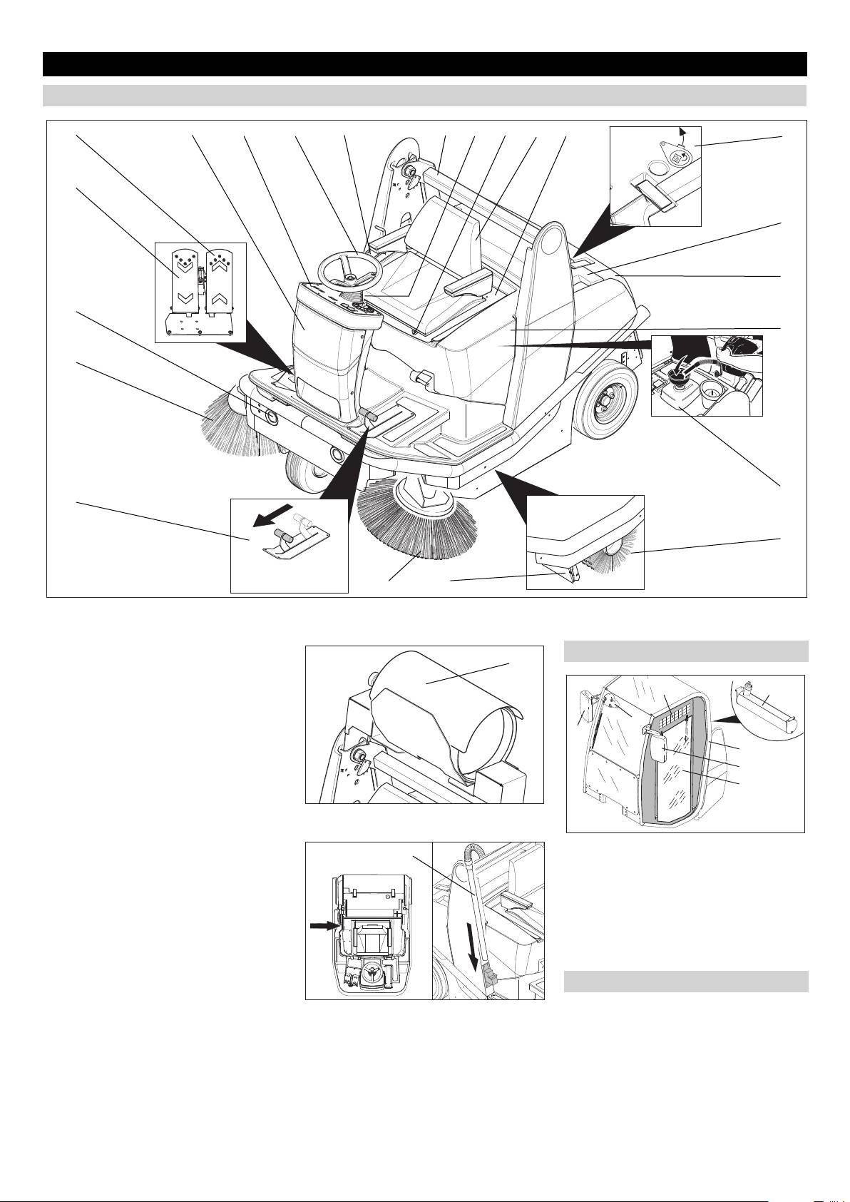
Operating and Functional Elements
Machines without driver cabin
5
4321 1213141516
17
6
18
19
7
20
8
21
11
22
910
Figure 2a
1 Operator control unit for waste contain-
Machines with driver cabin
er and parking brake
23
2 Steering wheel
72
3 Operator console
4 Fuses (behind front panel)
5 Accelerator pedal, forwards
3
4
6 Accelerator pedal, reverse
1
7 Lights
5
8 Right side brush
6
9 Left side brush
Figure 2b
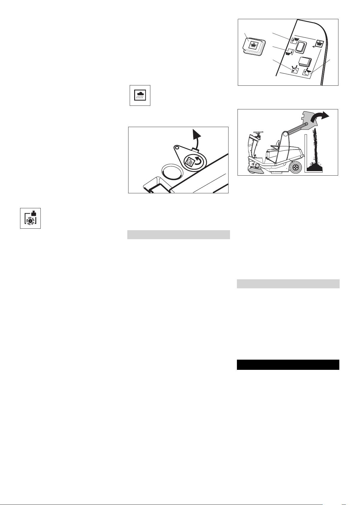
10 Bulk waste flap
11 Pedal for raising/lowering bulk waste
Figure 2d
flap
24
1 Driver cabin (optional)
12 Lift/tilt emptying mechanism
2 Tank
13 Lever for steering wheel adjustment
3 Turn on/off the wipers
14 Lever for seat adjustment
4 Right exterior mirror
15 Seat (with seat contact mat)
5 Left exterior mirror
16 Seat bracket
6 Plastic sheet doors
17 Wet/dry flap
7 Ventilation slots
18 Filter case
19 Waste container
Colour coding
20 Cover
Figure 2c
The operating elements for the cleaning
21 Tank
process are yellow.
22 Roller brush
The controls for the maintenance and
23 Gas cylinder (only KM 120/150 R LPG)
service are light gray.
24 Installation set suction hose (option)
24 EN
- 4
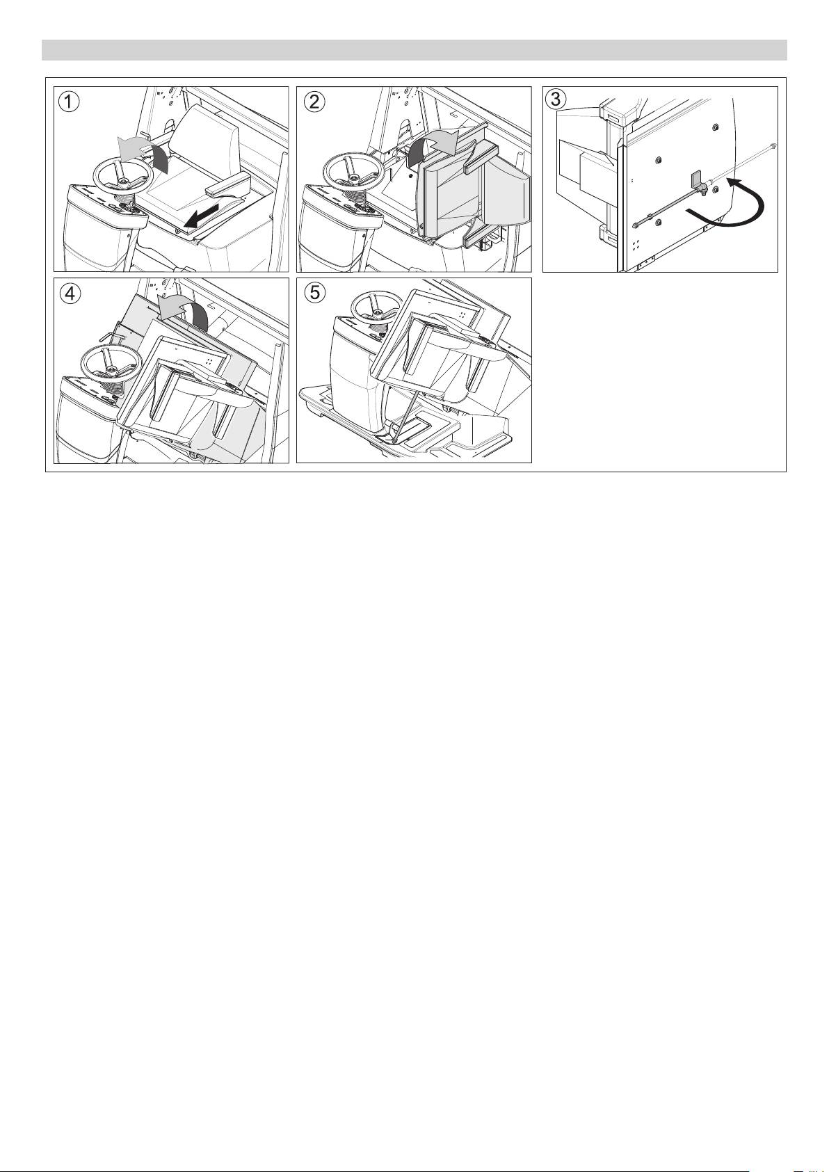
Opening/closing and securing cover
Figure 3
Danger
Risk of injury! When open, the cover must
be propped up using the retaining rod.
Figure 1
Operate steering wheel adjustment le-
ver and fold steering wheel forwards.
Operate seat adjustment lever and
slide seat forwards.
Figure 2
Fold seat bracket to the side.
Figure 3
Fold out retaining rod.
(only 120/150 KM without driver cabin)
Figure 4
Fold cover forwards.
Figure 5
Insert retaining rod into the recess next
to the bulk waste flap pedal.
(only 120/150 KM without driver cabin)
Follow this sequence in reverse order to
close the cover.
- 5
25EN
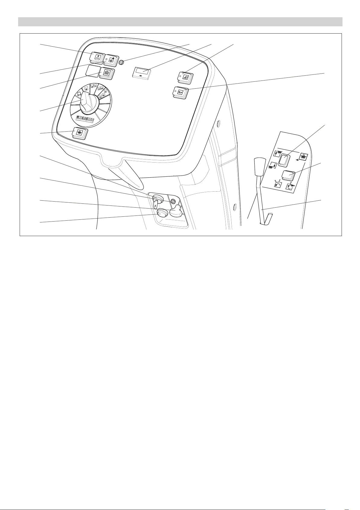
Operator console
3
567
4
8
16
1
9
2
12
10
13
14
11
15
Figure 4
1 Programme switch
2 Switch two-hand operations Lift/tilt
emptying mechanism
3 Button for filter shaker system
4 Button for power-operating mode
5 Indicator lamp for power-operating
mode
6 Elapsed-time counter with reset button
7 Switch for working lamp
8 Horn switch
9 Raise/lower waste container
10 Tilt waste container outwards/inwards
11 Parking brake
12 Ignition lock
13 Charge indicator lamp (only KM 120/
150 R D and LPG)
14 Choke (only KM 120/150 R G)
15 Remote button (only KM 120/150 R
LPG)
16 Wet cleaning switch, installation set
suction hose (option)
26 EN
- 6
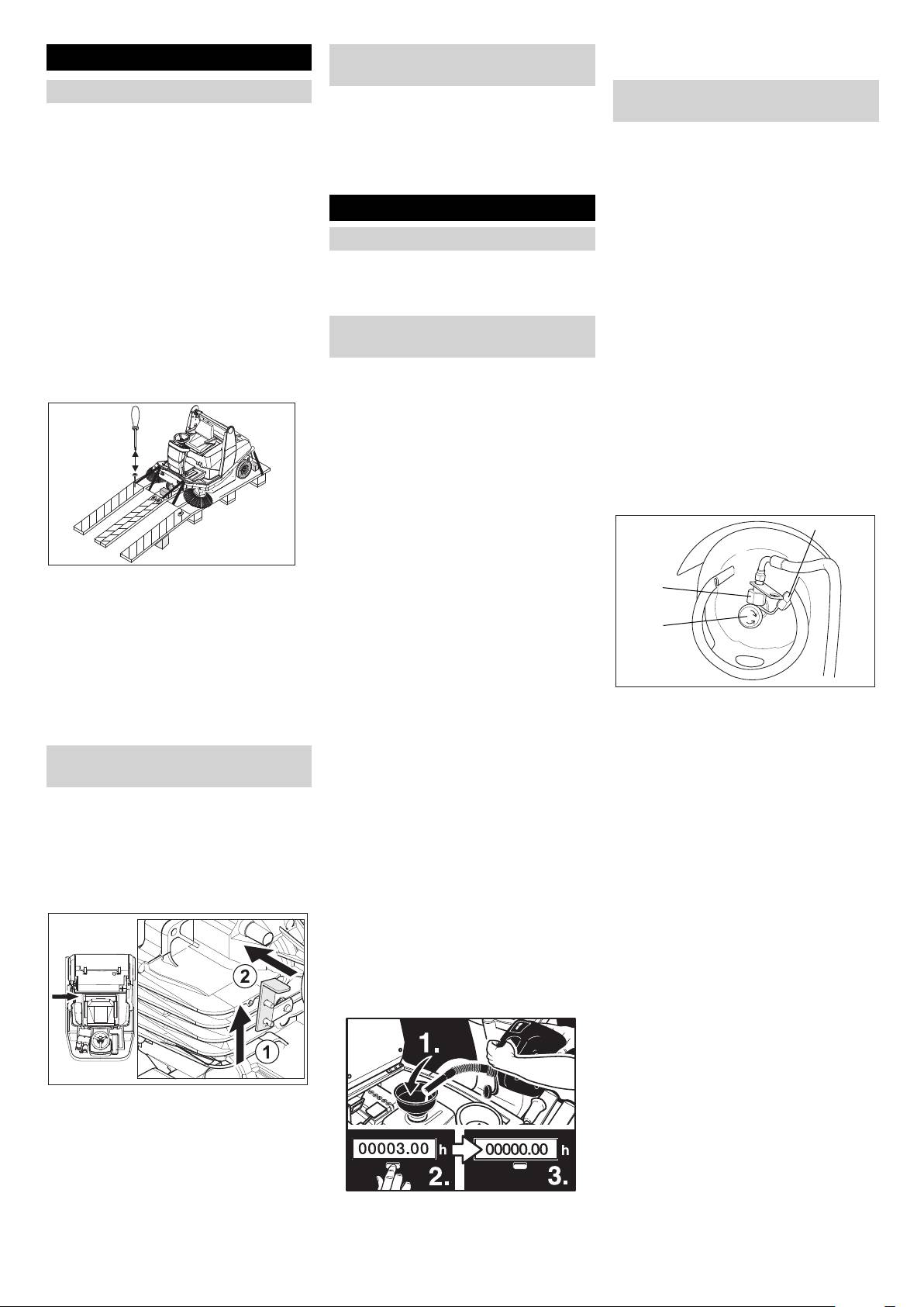
Press reset button (2) on the elapsed-
Before Startup
Moving sweeper by engaging self-
time counter.
propulsion
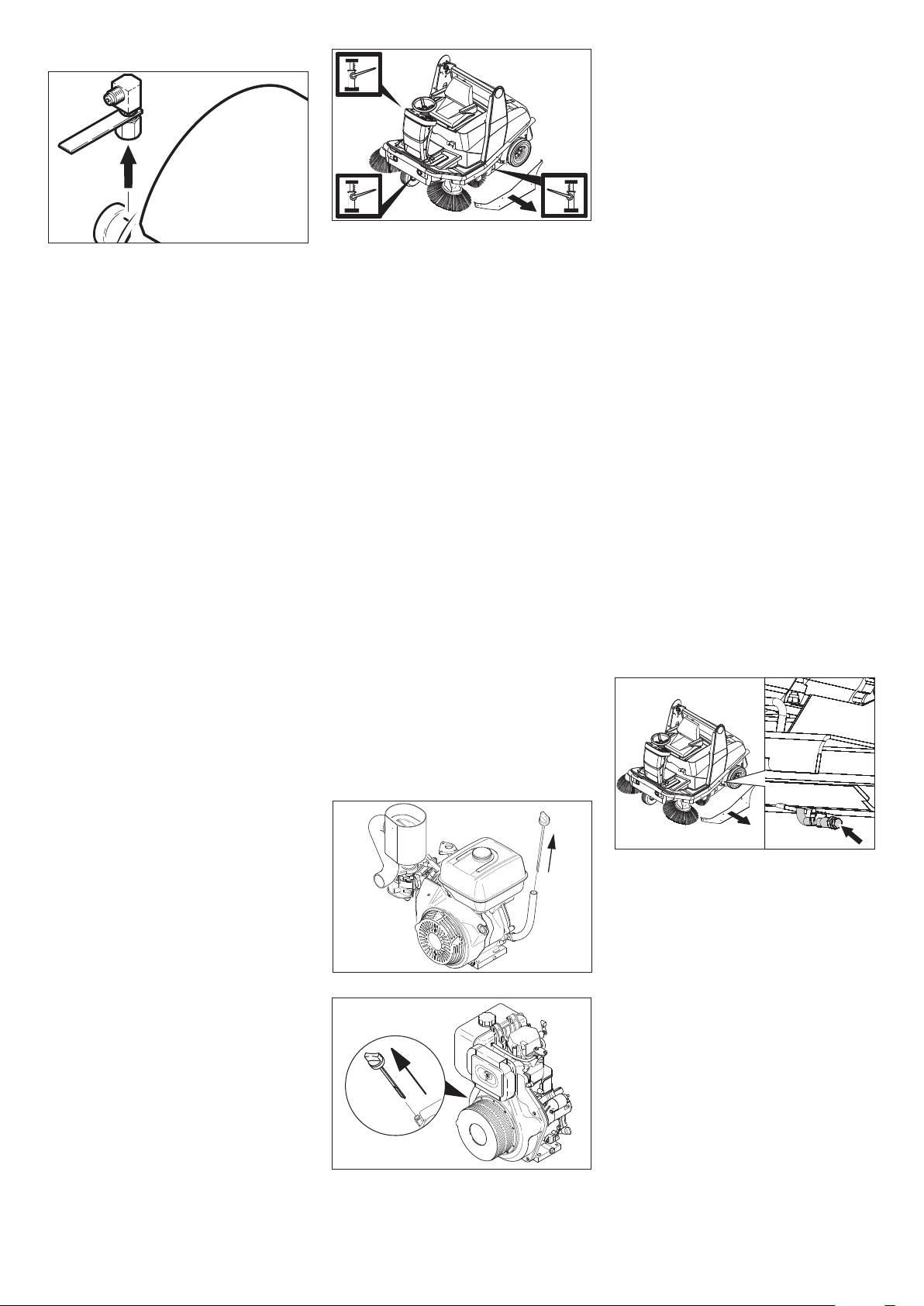
Unloading
Connect/ change gas cylinder (only
Unhook the free wheel lever.
KM 120/150 R LPG)
몇
Warning
The travel drive is now ready for operation.
Do not use a forklift truck to unload the ma-
Close cover.
몇 Warning
chine as this may damage it.
Release parking brake.
Only use replacement cylinders with 11 kg
To unload the machine, proceed as follows:
The appliance can now be driven.
contents of tested models.
Cut plastic packing belt and remove foil.
Danger
Connect battery (see section on Care
Start up
Risk of injury!
and maintenance)
– Follow safety regulations for LPG vehi-
General notes
Remove the elastic tape fasteners at
cles.
the stop points.
Park the sweeper on an even surface.
– Formation of crusts and yellow-frothing
Four indicated floor boards of the pallet
Remove ignition key.
deposits on the gas cylinder indicate
are fastened with screws. Unscrew
Lock parking brake.
leakiness.
these boards.
– Cylinders must be changed only by in-
Refuelling (only KM 120/150 R G and
Place the boards on the edge of the pal-
structed persons.
let. Place the boards in such a way that
R D)
– Cylinders containing propellant gases
they lie in front of the four wheels of the
Refuelling the machine
must not be changed in garages and
machine. Fasten the boards with screws.
underground areas.
Danger
– Do not smoke and use uncovered light
Risk of explosion!
while changing the cylinder.
– Only use the fuels specified in the Op-
– While changing cylinders, first close the
erations Manual.
locking valve of the LPG cylinder firmly
– Do not refuel the machine in enclosed
and immediately put the protective cap
spaces.
on the empty cylinder.
– Smoking and naked flames are strictly
prohibited.
1
– Ensure that no fuel reaches the hot
open surfaces.
Slide the four support beams included
Switch off engine.
2
in the packaging under the ramp.
Only KM 120/150 without driver cabin:
Remove the wooden blocks used for ar-
Open cover and secure it (Diag. 3).
resting the wheels and slide them under
3
Open fuel filler cap.
the ramp.
Insert funnel provided.
The machine can be moved in 2 ways:
KM 120/150 R G: Use regular unleaded
(1) By pushing it (see Moving sweeper
petrol.
Place the cylinder in such a way that the
without engaging self-propulsion).
KM 120/150 R D: Use diesel.
connection threading of the locking
(2) By driving it (see Moving sweeper by
Fill tank to max. 1 cm below the lower
valve vertically points upwards.
engaging self-propulsion).
edge of the filler nozzle.
Close the bracket closure.
Moving sweeper without engaging
Wipe off any spilt fuel, remove funnel
Attach safety splint.
self-propulsion
and close fuel filler cap.
Remove protective lid (1) from the con-
Only KM 120/150 without driver cabin:
Danger
nection valve of the cylinder.
Close cover.
Risk of injury! Before engaging the free-
Connect the gas tube with Union nut (2)
Resetting fuel gauge
wheel operation, the machine must be se-
(use 30 mm spanner).
cured to prevent it rolling away.
Note
Note
Lock parking brake.
After the machine is switched on, the num-
Connection has a left threading.
Open cover and secure it (Diag. 3).
ber of operating hours is displayed for 10
몇 Warning
seconds. The fuel gauge is then automati-
Open the gas drawing valve (3) only after
cally displayed.
starting the appliance (refer chapter Start-
Note
ing the appliance).
The fuel gauge shows the length of time the
machine has been in operation since the
elapsed-time counter was last reset.
Engage freewheel lever in hole.
This blocks the travel drive function.
Close cover.
Release parking brake.
The machine can now be pushed.
Note
Do not move the machine for long distanc-
Note
es without engaging self-propulsion, a
The machine can be operated for a maxi-
speed of 6 km/h should not be exceeded.
mum of 3 hours on a full tank.
- 7
27EN
Only KM 120/150 R LPG: Press remote
Inspection and maintenance work
Starting the machine
switch for 5 seconds, then release it.
Check engine oil level. *
Note
Turn ignition key past position 1.
Only KM 120/150 R G and R D: Check
The machine is equipped with a seat con-
If the machine starts, release the igni-
fill level of fuel tank. *
tact mat. If the driver's seat is vacated, the
tion key.
Only KM 120/150 R LPG: Check and
machine is switched off.
Note
ensure that the Union nut is fixed prop-
NOTICE
Never operate the starter motor for longer
erly on the gas tube. *
Only KM 120/150 R G and R LPG: Device
than 10 seconds. Wait at least 10 seconds
Check hydraulics fluid fill level. *
starts only if the immobilising brakes are
before operating the starter motor again.
Check side brush. *
applied (parking position).
Note
Check roller brush. *
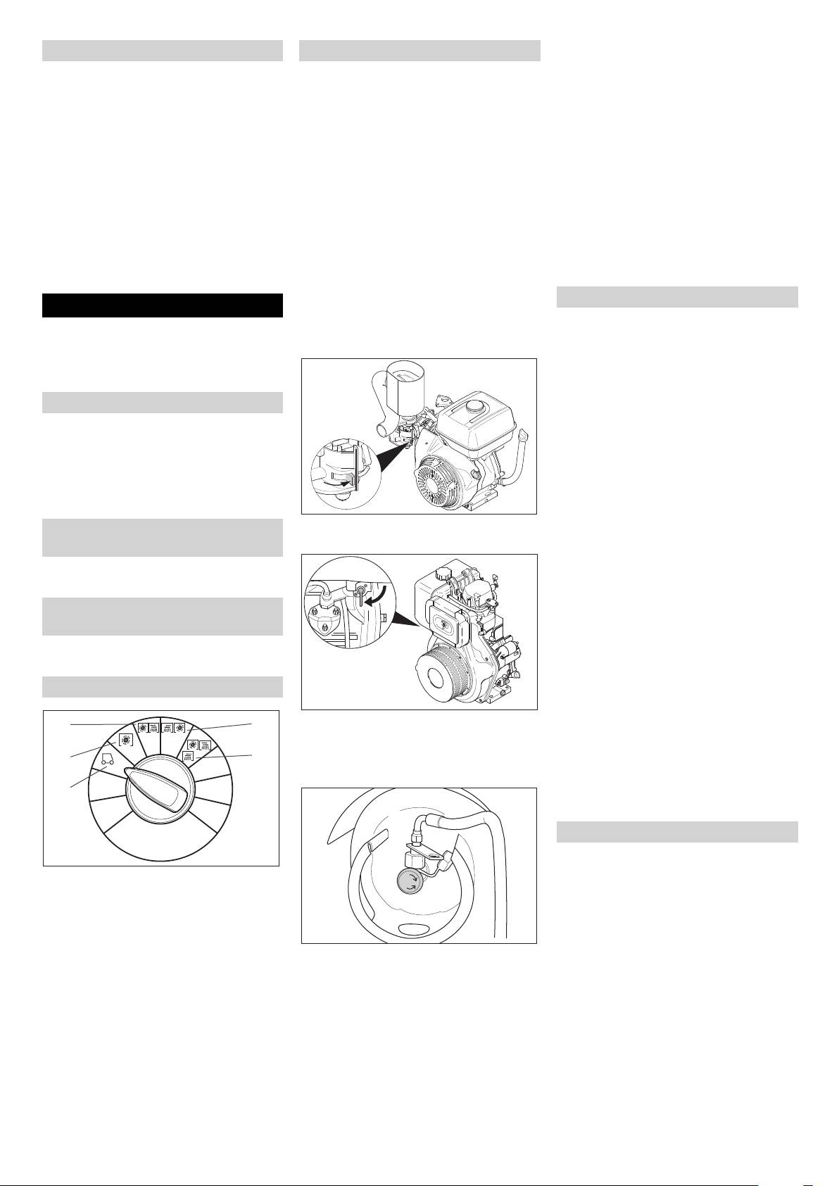
Open fuel tap (only KM 120/150 R G and
Operation during winter: When starting at
Empty waste container.
R D)
temperatures below +10 °C, the parking
Check tyre pressure. *
Note
brake is to be applied to disengage the en-
* For description, see section on Care and
The fuel cock is supplied from the factory
gine from the transmission and therefore
maintenance.
open. If the machine has been out of use
assist the starting process.
for a longer period of time, open the fuel
Drive the machine
Operation
cock.
Release parking brake.
Open cover and secure it (Diag. 3).
몇 Warning
KM 120/150 R G:
Drive forward
The air inlets next to the driver's seat must
Press right accelerator pedal down
not be covered. Do not store any objects
slowly.
next to or behind the seat.
Reverse drive
Adjusting driver's seat
Danger
Pull seat adjustment lever outwards.
Risk of injury! While reversing, ensure that
Slide seat, release lever and lock in
there is nobody in the way, ask them to
place.
move if somebody is around.
Check that the seat is properly locked in
Press left accelerator pedal down slowly.
position by attempting to move it back-
Note
wards and forwards.
Driving method
Push lever in "ON" direction.
Adjusting the external mirror (only
– The accelerator pedal can be used to
KM 120/150 R D:
KM 120/150 without driver cabin)
vary the driving speed infinitely.
– Avoid pressing the pedal suddenly as
Adjust the left and right exterior mirror
this may damage the hydraulic system.
manually.
– In the event of power loss on inclined
Switching on/off the wipers (only
surfaces, slightly reduce the pressure
KM 120/150 without driver cabin)
on the accelerator pedal.
Press the switch for windscreen washer
Brakes
system.
Release the accelerator pedal, the ma-
chine brakes automatically and stops.
Programme selection
Driving over obstacles
Turn lever to position "O".
Driving over fixed obstacles which are 50
3
4
mm high or less:
Close cover.
Drive forwards slowly and carefully.
2
5
Open gas supply (only KM 120/150 R
Driving over fixed obstacles which are
LPG)
more than 50 mm high:
1
Only drive over these obstacles using a
suitable ramp.
Sweeping mode
Danger
1 Driving
Risk of injury! If the bulk waste flap is open,
Driving to the Place of Use.
stones or gravel may be flung forwards by
2 Sweeping with sweep roller
the roller brush. Make sure that this does
Roller brush is lowered.
not endanger persons, animals or objects.
3 Sweeping with right side brush
몇 Warning
Open the gas drawing valve by turning
Sweep roller and right side brush are
Do not sweep up packing strips, wire or
it in anti-clockwise direction.
lowered.
similar objects as this may damage the
4 Sweep using left side brush (optional)
Turning on the Appliance
sweeping mechanism.
Lock parking brake.
Sweep roller and left side brush are
몇 Warning
lowered.
Sit on the driver's seat.
To avoid damaging the floor, do not contin-
5 Sweep using both brushes (optional)
Do NOT press the accelerator pedal.
ue to operate the sweeping machine in the
Sweep roller and both brushes are low-
Set programme switch to step 1 (driv-
same position.
ered.
ing).
Note
Only KM 120/150 R G: Press choke le-
To achieve an optimum cleaning result, the
ver downwards. Once the engine is run-
driving speed should be adjusted to take
ning, pull choke lever back up.
specific situations into account.
28 EN
- 8
Note
Set programme switch to step 5. Both
side brushes and roller brush are low-
During operation, the waste container
ered.
should be emptied at regular intervals.
1
2
Note
Note
Roller brush and side brush start operating
3
When cleaning surfaces, only lower the
automatically.
roller brush.
45
Note
Sweeping dry floors
Close wet/dry flap on waste container.
Also lower side brush when cleaning along
edges.
Installation set suction hose (option):
Sweeping with roller brush (basic-oper-
Raise waste container. Press button 1
ating mode)
(operator console) and 2 simultaneous-
Note
ly.
Two operating modes are possible with the
Press wet sweeping button repeatedly.
roller brush. In the basic-operating mode,
Sweeping damp or wet floors
the roller brush is only subjected to a small
amount of wear and tear.
Set programme switch to step 2. Roller
brush is lowered.
Sweeping with roller brush (power-oper-
ating mode)
Note
Two operating modes are possible with the
roller brush. Power-operating mode in-
Once the required height has been
creases cleaning performance.
reached:
Set programme switch to step 2. Roller
Tip waste container out. Press button 1
Open wet/dry flap on waste container.
brush is lowered.
(operator console) and 5 simultaneous-
Installation set suction hose (option):
ly.
Press wet sweeping button.
Tip waste container back in. Press but-
Note
ton 1 (operator console) and 4 simulta-
This protects the filter from moisture.
neously.
Press power button. Indicator lamp
Lower waste container. Press button 1
Emptying waste container
lights up.
(operator console) and 3 simultaneous-
Note
ly.
Note
Wait until the automatic filter shaking proc-
The following actions reset the power but-
Note
ess is finished and the dust has settled be-
ton automatically:
The container can only be fully retracted if
fore you open or empty the waste
– Press the power button again.
it is tipped back into its starting position be-
container.
– Set programme switch to step 1 (driv-
forehand.
ing).
Danger
Turn off the appliance
– Switching off the machine.
Risk of injury! When emptying the waste
The indicator lamp goes out and the basic-
container, care should be taken to ensure
Set programme switch to step 1 (driv-
operating mode is activated.
that no persons or animals are within its
ing). The side brush and roller brush are
swivelling range.
raised.
Note
Turn ignition key to "0" and remove it.
Danger
To sweep up larger items with a height of
Lock parking brake.
60 mm, e.g. soft drink cans, the bulk waste
Danger of crushing. Never reach into the
flap must be raised briefly.
rod assembly for the drainage mechanism.
Note
Stay away from the area under the raised
Once the machine has been switched off,
Sweeping with bulk waste flap raised
container.
the dust filter is shaked automatically for
Raising bulk waste flap:
Danger
approx. 15 seconds.
Press the pedal for the bulk waste flap
forwards and keep pressed down.
Danger of tipping. Place the machine on an
even surface during emptying.
Shutdown
To lower it, take foot off pedal.
Stop the machine.
Note
If the sweeper is going to be out of service
Set programme switch to step 1 (driv-
An optimum cleaning result can only be
for a longer time period, observe the follow-
ing).
achieved if the bulk waste flap has been
ing points:
Note
lowered completely.
Park the sweeper on an even surface.
The container can only be tilted and emp-
Only KM 120/150 R G and R D: Fill fuel
Sweeping with side brushes
tied once a set minimum level has been
tank and close fuel cock.
To sweep in edge area on right-hand side:
reached.
Only KM 120/150 R LPG: Close the gas
Set programme switch to step 3. The
Note
cylinder valve and remove the cylinder.
right side brush and roller brush are
Store the gas cylinder according to the
lowered.
A two-handed operation is required to carry
safety regulations for LPG vehicles.
To sweep in edge area on left-hand side:
out the following steps.
Change engine oil.
Set programme switch to step 4. The
Set programme switch to step 1 (driv-
left side brush and roller brush are low-
ing). The roller brush and side brushes
ered.
are raised to prevent the bristles being
To sweep in edge areas on right- and left-
damaged.
hand side:
Turn ignition key to "0" and remove it.
- 9
29EN
Only KM 120/150 R G and R LPG: Un-
– Use only roller brushes/ side-brushes
Transport
screw spark plugs and pour approx.
that are provided with the appliance or
3 cm³ of oil into the spark plug hole.
CAUTION
specified in the Operations Manual.
Crank the engine several times before
The use of other roller brushes/ side-
Risk of injury and damage! Observe the
replacing the spark plug. Screw in the
brushes can affect the safety of the ap-
weight of the appliance when you transport
spark plug.
pliance.
it.
Secure sweeper to prevent it rolling
– Do not clean the appliance with a water
몇 Warning
away, lock parking brake.
hose or high-pressure water jet (danger
In general, when shipping the machine, the
Clean the inside and outside of the
of short circuits or other damage).
freewheel lever must be engaged in the up-
sweeper.
per hole. Only once this has been done, will
Cleaning the inside of the machine
Park the machine in a safe and dry
the travel drive be ready for operation. The
place.
Danger
machine must always be moved up or
Disconnect battery.
Risk of injury! Wear dust mask and protec-
down slopes by engaging self-propulsion.
Charge battery approx. every 2 months.
tive goggles.
Turn ignition key to "0" and remove it.
Open cover and secure it (Diag. 3).
Close fuel tap (only KM 120/150 R G
Only KM 120/150 R G and R D: Empty
Clean machine with a cloth.
tank. Draw off fuel using suitable pump.
and R D)
Blow through machine with com-
Only KM 120/150 R LPG: Close the gas
Open cover and secure it (Diag. 3).
pressed air.
cylinder valve and remove the cylinder.
KM 120/150 R G:
Close cover.
Store the gas cylinder according to the
safety regulations for LPG vehicles.
External cleaning of the appliance
Secure the wheels of the machine with
Clean the machine with a damp cloth
wheel chocks.
which has been soaked in mild deter-
Secure the machine with tensioning
gent.
straps or cables.
Note
Lock parking brake.
Do not use aggressive cleaning agents.
Maintenance intervals
Note
Push lever in "OFF" direction.
The elapsed-time counter shows the timing
KM 120/150 R D:
of the maintenance intervals.
Maintenance by the customer
Daily maintenance:
Check engine oil level.
Check axle drive oil level.
Check tyre pressure.
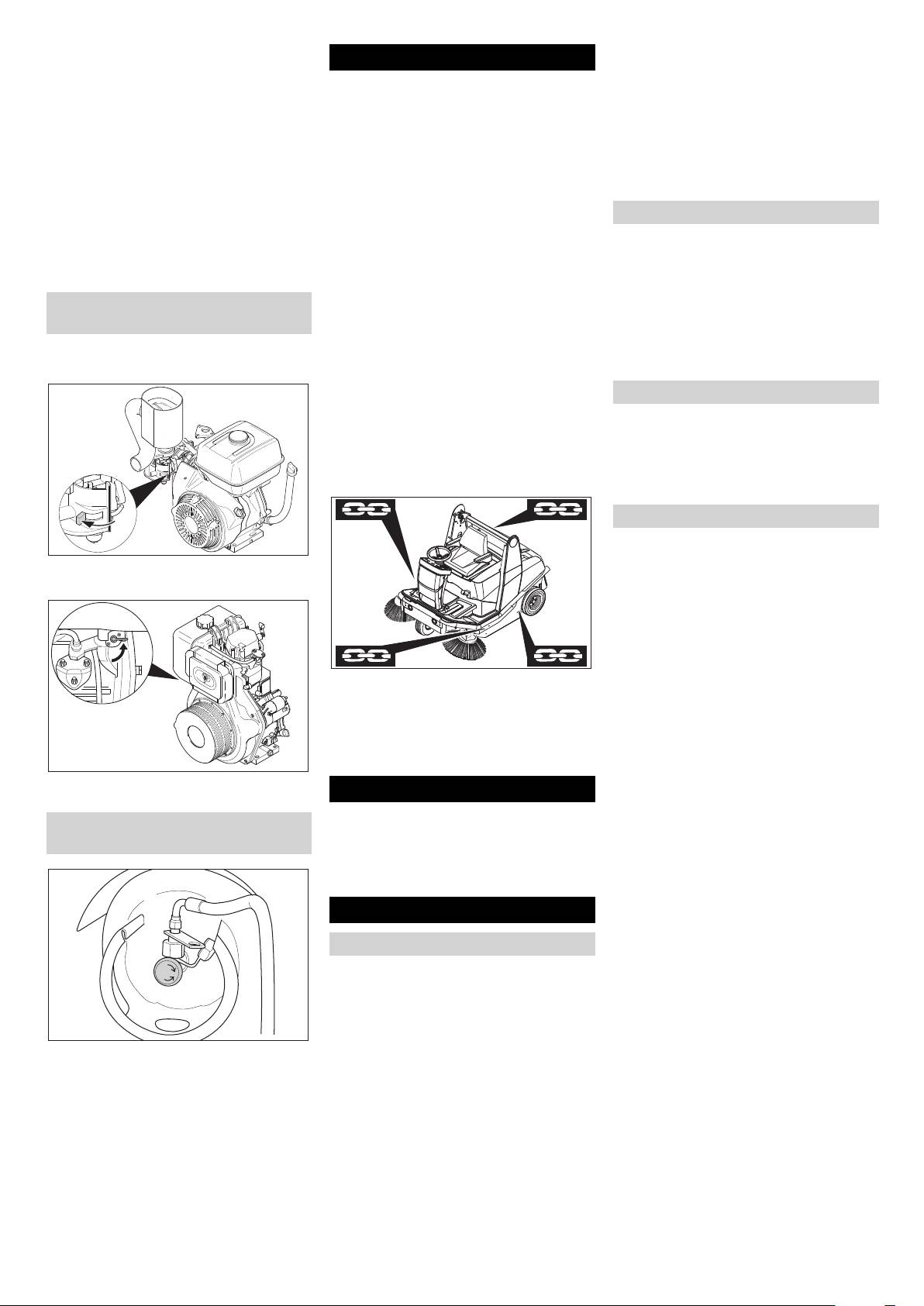
Note
Only KM 120/150 R LPG: Check gas
Observe markings for fixing points on base
pipes and connecting screws.
frame (chain symbols). When loading or
Only KM 120/150 R LPG: Check gas fil-
unloading the machine, it may only be op-
ter in the screw to the gas cylinder to
erated on gradients of max. 18%.
see if it is dirty, clean it if required (every
Turn lever to position "S".
time you change the cylinder).
Storing the device
Close cover.
Check function of all operator control el-
CAUTION
ements.
Close gas supply (only KM 120/150
Weekly maintenance:
Risk of injury and damage! Note the weight
R LPG)
Check leakiness of fuel or gas connec-
of the appliance in case of storage.
tions.
Park the machine in a safe and dry place.
Check return-line filter for sweeping
system.
Maintenance and care
Check air filter.
General notes
Check oil level of sweeper hydraulics.
Check hydraulic lines for leaks.
First switch off the appliance and re-
Check moving parts for freedom of
move the ignition key before performing
movement.
any cleaning or maintenance tasks on
Check the sealing strips in the sweep-
the appliance, replacing parts or switch-
ing area for position and wear.
ing over to another function.
Close gas drawing valve by turning it in
Maintenance to be carried out every 100
Pull out the battery plug or clamp the
clock-wise direction.
operating hours:
battery while working on the electrical
Check leakiness of fuel or gas connec-
unit.
tions.
– Maintenance work may only be carried
Change engine oil (initial change after
out by approved customer service out-
20 operating hours).
lets or experts in this field who are famil-
Only KM 120/150 R G and R LPG:
iar with the respective safety
Check spark plug.
regulations.
Check function of seat contact mat.
– Mobile appliances used for commercial
Check battery acid level.
purposes are subject to safety inspec-
tions according to VDE 0701.
30 EN
- 10
Check tension, wear and function of
Connect pole terminal (red cable) to
drive belts (V-belt and circular belt).
Please do not release engine
positive pole (+).
Maintenance following wear:
oil, fuel oil, diesel and petrol
Connect pole terminal to negative pole
Replace sealing strips.
into the environment. Protect
(-).
Replace roller brush.
the ground and dispose of
Charging battery
Replace side brush.
used oil in an environmentally-
Danger
clean manner.
For description, see section on Mainte-
Risk of injury! Comply with safety regula-
nance work.
Safety notes regarding the batteries
tions on the handling of batteries. Observe
Note
Please observe the following warning notes
the directions provided by the manufacturer
Where maintenance is carried out by the
when handling batteries:
of the charger.
customer, all service and maintenance
Disconnect battery.
work must be undertaken by a qualified
Observe the directions on the
Connect positive terminal cable from
specialist. If required, a specialised Kärch-
battery, in the instructions for
the charger to the positive pole connec-
er dealer may be contacted at any time.
use and in the vehicle operat-
tion on the battery.
Maintenance by Customer Service
ing instructions!
Connect negative terminal cable from
Maintenance to be carried out after 20 op-
the charger to the negative pole con-
Wear an eye shield!
erating hours:
nection on the battery.
Carry out initial inspection.
Plug in mains connector and switch on
Maintenance to be carried out every 100
charger.
operating hours
Charge battery using lowest possible
Maintenance to be carried out every 200
Keep away children from acid
level of charging current.
operating hours
and batteries!
Check fluid level in the battery and ad-
Maintenance to be carried out every 300
just if required
operating hours
몇 Warning
Note
Risk of explosion!
Regularly check the fluid level in acid-filled
In order to safeguard warranty claims, all
batteries.
service and maintenance work during the
Unscrew all cell caps.
warranty period must be carried out by the
Where fluid level is too low, top up cells
authorised Kärcher Customer Service in
Fire, sparks, open light, and
to the mark provided with distilled wa-
accordance with the maintenance booklet.
smoking not allowed!
ter.
Maintenance Works
Charge battery.
Screw in cell caps.
Preparation:
Park the sweeper on an even surface.
Danger of causticization!
Remove the battery
Turn ignition key to "0" and remove it.
Note
Lock parking brake.
Before removing the battery, make sure
General notes on safety
that the negative pole lead is disconnected.
Danger
First aid!
Check that the battery pole and pole termi-
nals are adequately protected with pole
Risk of injury! While working around the lift/
grease.
tilt emptying mechanism, raise the waste
Open cover and secure it (Diag. 3).
container to its highest point and secure.
Disconnect battery.
Warning note!
Remove the battery from the battery
holder.
Dispose of the used battery according
to the local provisions.
Disposal!
Check fuel indicator (only KM 120/150
R G and R D)
Note
After the machine is switched on, the num-
Do not throw the battery in the
ber of operating hours is displayed for 10
dustbin!
Insert safety support into the piston rod
seconds. The fuel gauge is then automati-
for the lifting cylinder and secure it.
cally displayed.
Danger
Note
Risk of injury due to engine overrun. Once
Danger
The fuel gauge shows the length of time the
the engine has been switched off, wait for 5
Risk of explosion! Do not put tools or similar
machine has been in operation since the
seconds. Stay well clear of the working
on the battery, i.e. on the terminal poles
elapsed-time counter was last reset.
area for this time.
and cell connectors.
Note
Allow the machine sufficient time to cool
Danger
The machine can be operated for a maxi-
down before carrying out any mainte-
Risk of injury! Ensure that wounds never
mum of 3 hours on a full tank.
nance and repair work.
come into contact with lead. Always clean
Check fuel gauge for elapsed-time
Do not touch any hot parts, such as the
your hands after having worked with batter-
counter.
drive motor and exhaust system.
ies.
Installing and connecting the battery
Open cover and secure it (Diag. 3).
Insert battery in battery mount.
Screw on mounts on battery base.
- 11
31EN
Check gas filter (only KM 120/150 R LPG)
Note
Oil must be present on at least one third of
the oil dipstick. If the oil level is less than
this, top up engine oil until it reaches the
lower edge of the filler opening.
Only KM 120/150 R G and R LPG: Dis-
mantle the extension piece at the oil fill-
er opening.
Top up engine oil using 6.491-538 oil-
change pump.
Position vehicle jack at the appropriate
Only KM 120/150 R G and R LPG: In-
mounting point for the front or rear
stall the extension piece at the oil filler
Check gas filter in the screw to gas cyl-
wheel.
opening.
inder to see if it is dirty.
Raise machine using vehicle jack.
Close oil filler opening.
Clean dirty filters with compressed air.
Remove wheel nuts.
Wait at least 5 minutes.
Check gas connections (only KM 120/
Remove wheel.
Check engine oil level.
150 R LPG)
Mount spare wheel.
Oil grade: see Technical Data
Note
Screw on wheel nuts.
Change the engine oil
Inspection must be carried out by a quali-
Lower machine using vehicle jack.
Pull out oil dipstick.
fied specialist.
Tighten wheel nuts.
Only KM 120/150 R G and R LPG: Dis-
Check gas connections, pipes and
Screw on side panel.
mantle the extension piece at the oil fill-
evaporators using leak-search spray for
er opening.
leaks.
Note
Suck off engine oil using 6.491-538 oil-
Note
Use a suitable commercially available vehi-
change pump.
cle jack.
Leaks in the gas cylinder cause formation
Fill in new engine oil using 6.491-538
of crusts or yellow frothy deposits on the
Check engine oil level and top up, if re-
oil-change pump.
gas connections, pipes and evaporator.
quired
Oil grade: see Technical Data
Contact Kärcher Customer Service for
몇 Warning (only KM 120/150 R G and R
Only KM 120/150 R G and R LPG: In-
maintenance of the gas unit.
LPG)
stall the extension piece at the oil filler
Check the tyre pressure
The engine is equipped with an oil deficien-
opening.
Park the sweeper on an even surface.
cy switch. When the fill level is insufficient,
Close oil filler opening.
Connect air pressure testing device to
the engine switches off and can only be re-
Wait at least 5 minutes.
tyre valve.
started once the engine oil has been re-
Check engine oil level.
Check air pressure and adjust if re-
plenished.
Only KM 120/150 R G and R LPG: The mo-
quired.
Danger
tor oil can be drained via a hose.
Set air pressure for the front and rear
Risk of burns!
tyres at 6 bar.
Allow engine to cool down.
Replacing wheel
Wait for at least 5 minutes after switch-
ing off the engine before checking the
Danger
engine oil fill level.
Risk of injury!
Open cover and secure it (Diag. 3).
Park the sweeper on an even surface.
KM 120/150 R G and R LPG:
Remove ignition key.
When carrying out repairs on public
highways, wear warning clothing when
working close to passing traffic.
Check stability of ground. Also secure
Danger
the machine with wheel chock(s) to pre-
Risk of burns due to hot oil!
vent it rolling away.
Ready a catch bin for appr. 1.5 litre oil.
Lock parking brake.
Allow engine to cool down.
Check tyres
Open quick-release locks on the left-
Check tyre contact face for foreign ob-
hand side panel.
jects.
Remove side panel.
Remove objects found.
KM 120/150 R D:
Remove the oil drain hose from the
Use suitable, commercially available
holder.
materials to carry out tyre repairs.
Unscrew oil drain plug.
Note
Pull out oil dipstick.
Observe the manufacturer's recommenda-
Drain off oil.
tions. The journey may be resumed provid-
Screw in oil drain plug.
ing that the directions supplied by the
Insert the oil drain hose in the holder.
product manufacturer have been observed.
The tyre/wheel change should nonetheless
be carried out as soon as possible.
Open quick-release locks on the rele-
vant side panel.
Pull out oil dipstick.
Remove side panel.
Wipe off oil dipstick and insert.
Loosen wheel nuts.
Pull out oil dipstick.
32 EN
- 12
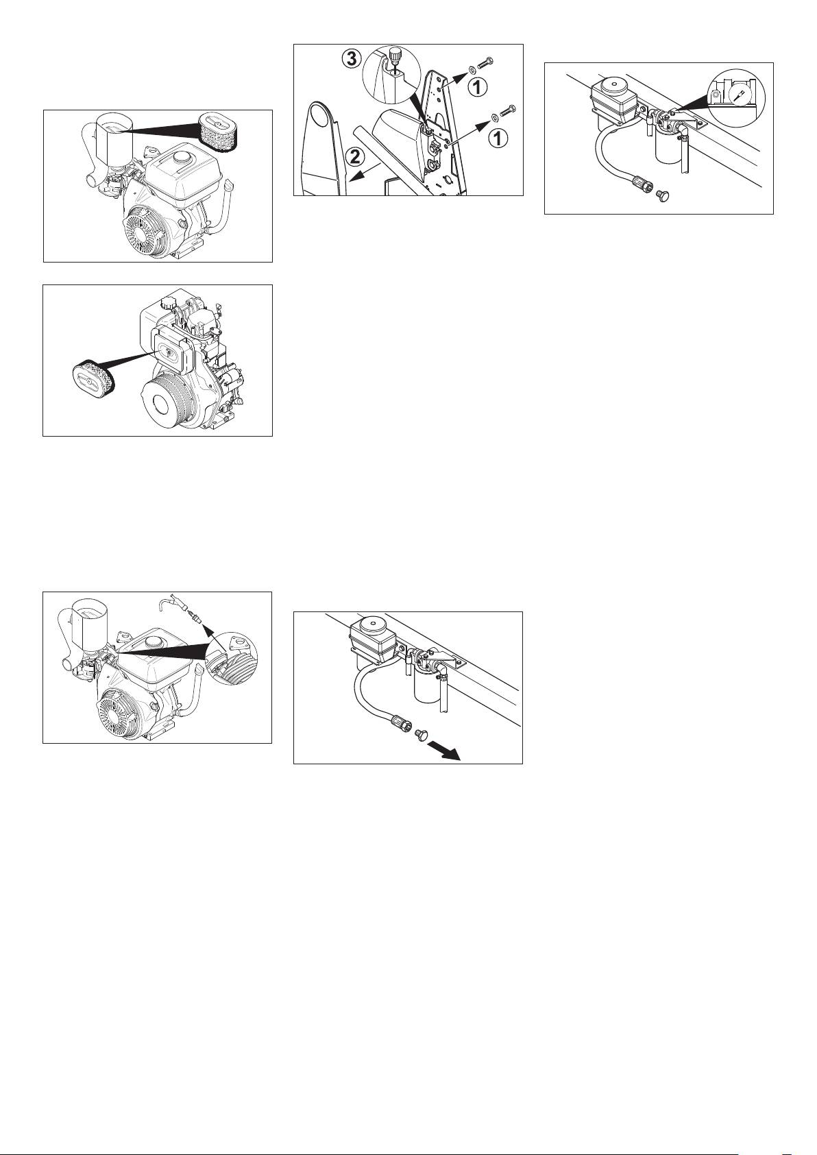
Check air filter and replace, if necessary
Check oil filter/Check backflow pressure
Open cover and secure it (Diag. 3).
KM 120/150 R G and R LPG:
Loosen screws (1).
Remove panel (2).
The oil filter needs to be cleaned or re-
Open the lock with the oil dipstick (3).
placed if the manometer display is in
Check oil level using the oil dipstick.
the red area.
KM 120/150 R D:
Note
Check side brush
The oil level must lie between “MIN“ and
Park the sweeper on an even surface.
“MAX“.
Set programme switch to step 1 (driv-
Top up hydraulic oil if necessary.
ing). Side brushes lift up.
Close container.
Turn ignition key to "0" and remove it.
Screw on panel.
Check side brush.
Oil grade: see Technical Data
Note
Check and adjust hydraulic fluid fill level
The side brush floating mounting adjusts
and change oil – axle drive circuit
the sweeping track as the bristles wear
Note
down. The side brush must be replaced if it
The sweeper is equipped with 2 hydraulic
becomes too worn.
Unscrew wing nut.
circuits.
Replacing side brush
Remove, check and clean filter car-
(1) Checking fill level
Park the sweeper on an even surface.
tridge.
Raise waste container.
Set programme switch to step 1 (driv-
Use either a new or cleaned filter car-
Insert safety support into the piston rod
ing). Side brushes lift up.
tridge in the vacuum container.
for the lifting cylinder and secure it.
Turn ignition key to "0" and remove it.
Screw on wing nut.
Check the fill level in the header tank.
Loosen 3 retaining nuts on underside.
Clean and change spark plug (only KM
Note
Clip side brush on to driver and screw
120/150 R G and R LPG)
The oil level must lie between the “MAX“
on.
Open cover and secure it (Diag. 3).
mark and a distance of 2 cm above the
Checking roller brush
base of the tank.
Park the sweeper on an even surface.
Set programme switch to step 1 (driv-
ing). Roller brush is raised.
Turn ignition key to "0" and remove it.
Secure the machine with wheel
chock(s) to prevent it from rolling away.
Lock parking brake.
Remove belts or cords from roller
brush.
Remove spark-plug connector.
Replacing roller brush
Unscrew and clean spark plug.
Replacement is due if a visible deteriora-
몇 Warning
Screw in cleaned or new spark plug.
tion in sweeping performance caused by
This inspection may only be carried out
bristle wear is evident.
Push on spark-plug connector.
when the engine is cold.
Park the sweeper on an even surface.
Check and adjust fill level of hydraulic
(2) Adjusting fill level
Set programme switch to step 1 (driv-
fluid – sweeping hydraulics circuit
Raise waste container.
ing). Roller brush is raised.
Note
Insert safety support into the piston rod
Turn ignition key to "0" and remove it.
The sweeper is equipped with 2 hydraulic
for the lifting cylinder and secure it.
Secure the machine with wheel
circuits.
Remove the lid of the container.
chock(s) to prevent it from rolling away.
Note
If required, top up oil carefully.
Lock parking brake.
Drive in the waste container to check/ cor-
Close container.
Open quick-release locks on the right-
rect the filling status.
Oil grade: see Technical Data
hand side panel.
The cap with the oil dipstick is located in the
(3) Changing oil
storage tank above the right rear wheel.
Raise waste container.
Open cover and secure it (Diag. 3).
Insert safety support into the piston rod
for the lifting cylinder and secure it.
Unscrew oil drain plug.
Remove the lid of the container.
Drain off oil.
Screw in oil drain plug.
Replenish oil.
Close container.
- 13
33EN
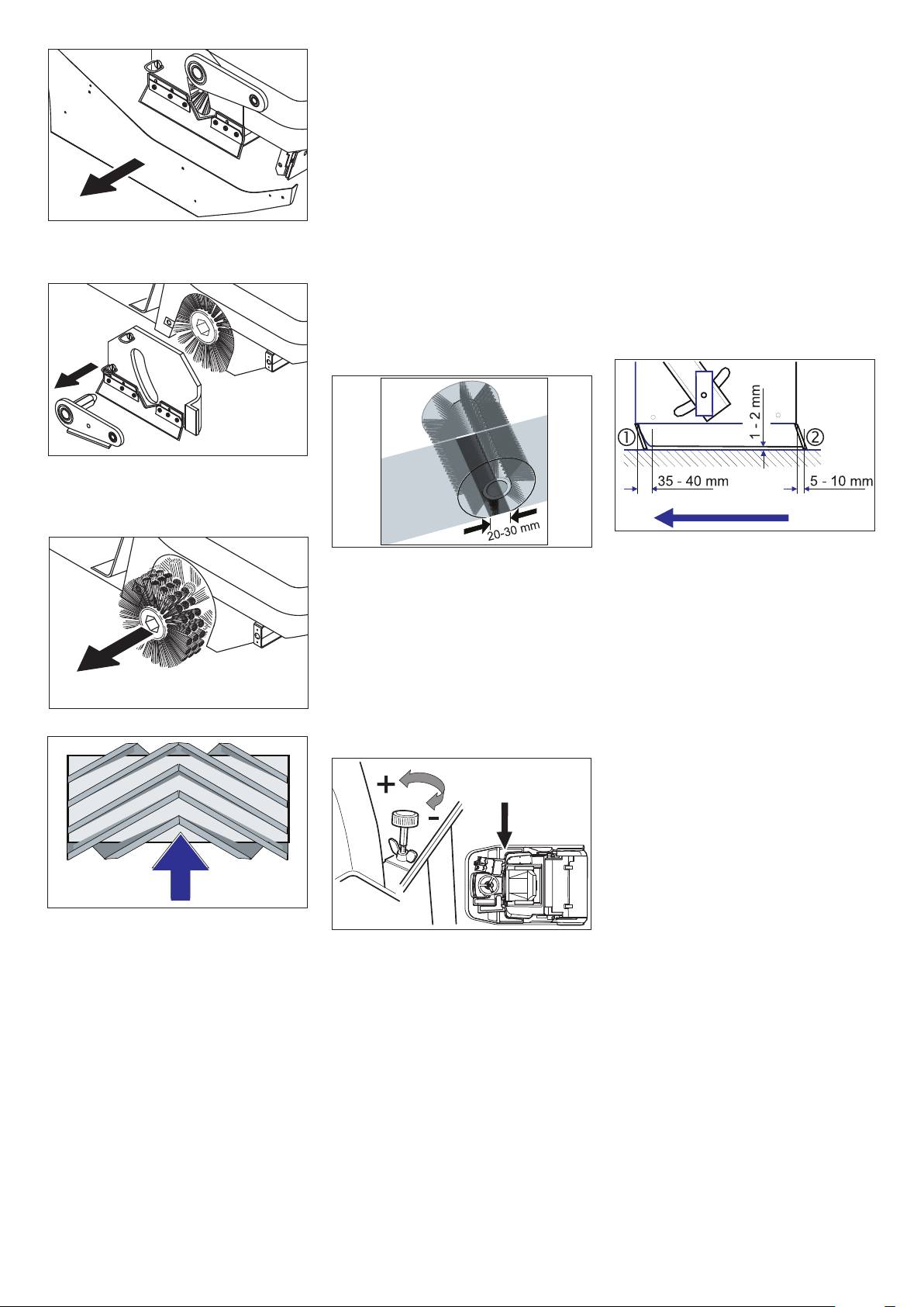
Check and adjust roller brush sweeping
Adjusting and replacing sealing strips
track
Park the sweeper on an even surface.
Note
Set programme switch to step 1 (driv-
To do this, the machine must be in basic-
ing). Roller brush is raised.
operating mode. The power button indica-
Turn ignition key to "0" and remove it.
tor light should not light up.
Secure the machine with wheel
Set programme switch to step 1 (driv-
chock(s) to prevent it from rolling away.
ing). The side brush and roller brush are
Lock parking brake.
raised.
Open the side panel quick-release
Drive sweeper on to a smooth, even
locks on both sides.
Remove side panel.
surface covered with a visible layer of
Remove side panels.
Unscrew and withdraw bolt on the roller
dust or chalk.
Front sealing strip
brush swinging arm.
Lower roller brush and allow it to briefly
Loosen retaining nuts for the front seal-
rotate.
ing strip (1) slightly (to replace, un-
Raise roller brush.
screw).
Press pedal which raises bulk waste
Screw on new sealing strip without fully
flap and keep pressed.
tightening the nuts.
Drive machine backwards.
Pull out roller brush swinging arm.
Remove lifting rod assembly from pins.
Open quick-release locks and remove
cover.
Adjust sealing strip.
The sweeping track should have an even
Set the distance of the sealing strip to
rectangular shape which is between 20 and
the floor so that the bottom edge trails
30 mm wide.
behind at a distance of between 35 and
Note
40 mm.
The shape of the sweeping track must not
Tighten nuts.
be trapezoidal. If so, consult Customer Ser-
Rear sealing strip
vice.
Set the distance between the sealing
Note
strip and the floor so that the bottom
edge trails behind at a distance of be-
The sweeping track can be adjusted using
Pull out roller brush.
tween 5 and 10 mm.
a handwheel in basic-operating mode.
Open cover and secure it (Diag. 3).
If worn, replace.
Remove roller brush.
Unscrew retaining nuts for rear sealing
strip (2).
Screw on new sealing strip.
Side sealing strips
Slightly loosen retaining nuts for the
side sealing strip (to replace, unscrew).
Screw on new sealing strip without fully
tightening the nuts.
Installation position of roller brush in direc-
To set the floor clearance, insert a
tion of travel
Release the wing nut.
sheet with a thickness of between 1 and
Push new roller brush into the roller
2 mm under the sealing strip.
Enlarging sweeping track:
brush housing and onto the drive pin.
Turn the adjustment screw in an anti-
Adjust sealing strip.
Note
clockwise direction (+).
Tighten nuts.
When installing the new roller brush, ensure
Reducing sweeping track:
Screw on side panels.
correct positioning of the bristle assembly.
Turn the adjustment screw in a clock-
Position roller brush cover.
wise direction (-).
Push lifting rod assembly on to pins.
Tighten the wing nut.
Push roller brush mount on to the pins.
Note
Tighten bolt on the roller brush mount.
In power-operating mode, the sweeping
Position retaining screws for the roller
track is automatically adjusted due to the
brush cover and screw home.
floating mounting for the side brush as the
Screw on side panel.
bristles wear down. The roller brush must
Note
be replaced if it becomes too worn.
Once the new roller brush has been in-
stalled, the sweeping track must be read-
justed.
34 EN
- 14
Check tension of drive belt and V-belt of
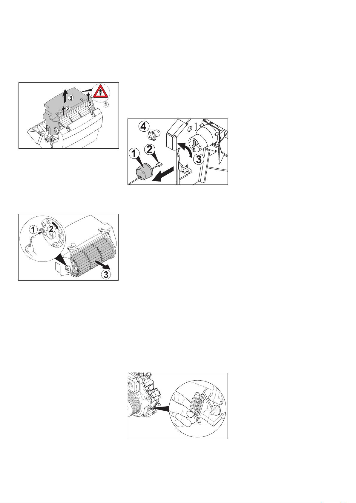
Replacing dust filter
the roller brush also check for wear or
Danger
damage.
Empty waste container before replacing
Only KM 120/150 R LPG and KM 120/
dust filter. Wear a dust mask when working
150 with driver cabin:
around the dust filter. Observe safety regu-
Check tension of drive belt and V-belt of
lations on the handling of fine particulate
the light machine; also check for wear
material.
or damage.
Slightly raise the waste container and
tipp it a little.
Check cup seal
Chek the cup seal at the suction blower
regularly to see that it sits properly.
Replacing electric bulb
Turn ignition key to "0" and remove it.
Remove side brush.
Disconnect filter motor from power sup-
ply (1).
Disconnect the plug connection of the
limit switch.
Loosen the screw joint of the filter agita-
tor motor.
Remove splash guard (1).
Open catches (2).
Disconnect plug (2).
Slightly tip the filter box backwards and
Twist contact plate to one side (3).
take it out (3).
Remove defective bulb (4).
Insert new bulb.
Twist contact plate back into original
position.
Connect plug.
Mount splash guard.
Screw on side brush.
Replacing fuses of drive control/ elec-
tronic system
The drive control/electronic system is in-
stalled behind the front panel. To replace a
Loosen filter mount (1), turn (2) and pull
fuse, the front panel must be removed.
out.
Loosen screws on both sides of the
Remove louver filter (3).
panel.
Insert new filter.
Note
Make sure driver engages with grooves
The assignment of fuses is indicated on the
on drive side.
inside of the front panel. Only use fuses
Snap filter mount back on and tighten
with identical safety ratings.
screws.
Replace defective fuses.
Note
Replace front panel.
Make sure when installing the new filter
Replacing electrical starter in the engine
that the fins are not damaged and the filter
room (only KM 120/150 R D)
case seal does not get jammed.
Open cover and secure it (Diag. 3).
Replacing filter case seal
Lift filter case seal out of groove in the
cover.
Insert new seal.
Checking drive belt
Danger
The engine requires approx. 3-4 seconds
to come to a standstill once it has been
switched off. During this time, stay well
clear of the working area.
Turn ignition key to "0" and remove it.
Replace defective fuse.
Open cover and secure it (Diag. 3).
Check tension of drive belt and V-belt of
the suction blower, also check for wear
or damage.
- 15
35EN

Troubleshooting
Fault Remedy
Appliance cannot be started Sit on the driver seat, activate seat contact mat
Refuel/ replace gas cylinder
Open fuel tap/ gas supply
Check connections and links in petrol or gas lines.
Check fuse of the electrical starter, replace if required (only KM 120/150 R D)
Charging battery
Clean and change spark plug, replace if required (only KM 120/150 R G and R LPG)
Inform Kärcher Customer Service.
For temperatures below +10 °C: Lock parking brake
Engine is running erratically Clean or replace air filter
Check connections and links in petrol or gas lines.
Inform Kärcher Customer Service.
Engine is running but machine is
Release parking brake
not moving
Check setting of freewheel lever
Inform Kärcher Customer Service.
Engine is running but machine is
Release parking brake
only moving slowly
Allow machine to warm up for approx. 3 minutes in sub-zero temperatures
Inform Kärcher Customer Service.
Machine is not sweeping properly Check roller brush and side brushes for wear, replace if necessary.
Check function of bulk waste flap
Check sealing strips for wear, adjust or replace as required
Adjust roller mirror
Check hydraulic system (sweeping) for leaks.
Inform Kärcher Customer Service.
Dust gathers in the machine Empty waste container
Check suction fan drive belt
Check sealing cover on suction fan
Check dust filter, clean or replace
Check filter case seal
Check sealing strips for wear, adjust or replace as required
Poor cleaning performance at
Replace side brush
edges
Check sealing strips for wear, adjust or replace as required
Inform Kärcher Customer Service.
Side brush or roller brush switch-
Check hydraulic system (sweeping) for leaks.
on operation is not working
Inform Kärcher Customer Service.
Side brush or roller brush is not
Inform Kärcher Customer Service.
being lowered
Insufficient vacuum performance Check filter case seal
Check sealing cover on suction fan
Insert lamella filter correct; see Changing dust filter
Roller brush does not turn. Remove belts or cords from roller brush
Charge indicator lamp glows only
Inform Kärcher Customer Service.
during operations (only KM 120/
150 R D and R LPG)
36 EN
- 16

Technical specifications
KM 120/150 R G KM 120/150 R D KM 120/150 R LPG
Machine data
Length x width x height (without driver cabin) mm 1900 x 1230 x 1400 1900 x 1230 x 1400 1900 x 1230 x 1800
Length x width x height (with driver cabin) mm 1900 x 1230 x 2010 1900 x 1230 x 2010 1900 x 1230 x 2010
Length x width x height (with driver cabin and beacon
mm 1900 x 1230 x 2205 1900 x 1230 x 2205 1900 x 1230 x 2205
light)
Unladen weight (without attachment sets) kg 660 670 710
Permissible overall weight kg 1110 1120 1160
Driving speed km/h 10 10 10
Cleaning speed km/h 8 8 8
Max. climbing performance (appliance without driver
%181818
cabin)
Max. climbing performance (appliance with driver
%101010
cabin)
Roller brush diameter mm 300 300 300
Roller brush width mm 850 850 850
Side brush diameter mm 600 600 600
Surface cleaning performance without side brushes m
2
/h 6800 6800 6800
Surface cleaning performance with 2 side brushes m
2
/h 11588 11588 11588
Working width without side brushes mm 850 850 850
Working width with 2 side brushes mm 1470 1470 1470
Volume of waste container l 150 150 150
Protection type, drip-proof -- IPX 3 IPX 3 IPX 3
Engine
Type -- Honda, 1 cyl., four-
Yanmar L100AE, 1
Honda, 1 cyl., four-
stroke
cyl., four-stroke
stroke
Cylinder capacity cm
3
390 406 390
Max. power kW/PS 9,5/13 7,4/10 9,5/13
Maximum torque at 2500 rpm Nm 26,5 -- 26,5
Maximum torque at 2700 rpm Nm -- 27 --
Capacity of fuel tank, normal petrol (unleaded) l 6 -- --
Capacity of fuel tank, diesel l -- 5,5 --
Spark plug, NGK -- BPR 6 ES -- BPR 6 ES
Type of protection -- IP 22 IP 22 IP 22
Battery V, Ah 12, 44 12, 44 12, 44
Fuel consumption l/h ca. 2 ca. 1,3 --
Gas consumption kg/h -- -- ca.
Oil grades
SAE 15 W 40 engine l 1,1 1,65 1,1
Sweeping hydraulics -- HVLP 46 HVLP 46 HVLP 46
Axle drive -- SAE 20 W 50 SAE 20 W 50 SAE 20 W 50
Tyres
Size, front -- 4.00-4 4.00-4 4.00-4
Air pressure, front bar 6 6 6
- 17
37EN
Size, rear -- 4.00-8 4.00-8 4.00-8
Air pressure, rear bar 6 6 6
Brake
Service brake -- hydrostatic hydrostatic hydrostatic
Parking brake -- Hand lever (with
Hand lever (with
Hand lever (with
spring)
spring)
spring)
Filter and vacuum system
Filter surface area, fine dust filter m
2
999
Category of use – filter for non-hazardous dust -- U U U
Nominal vacuum, suction system mbar 12 12 12
Nominal volume flow, suction system l/s 50 50 50
Working conditions
Temperature °C -5 and +40 -5 and +40 -5 and +40
Air humidity, non-condensing % 0 - 90 0 - 90 0 - 90
Noise emission
Sound pressure level L
pA
dB(A) 82 83 82
Machine without driver cabin
Sound pressure level L
pA
dB(A) 88 88 88
Machine with driver cabin
Uncertainty K
pA
dB(A) 2 2 2
Sound power level L
WA
+ Uncertainty K
WA
dB(A) 101 100 100
Machine vibrations
Hand-arm vibration value m/s
2
<2,5 <2,5 <2,5
Seat m/s
2
<0,5 <0,5 <0,5
Uncertainty K m/s
2
0,2 0,2 0,2
KM 120/150 R LPG
EC Declaration of Conformity
Accessories
Measured: 98
We hereby declare that the machine de-
Guaranteed: 100
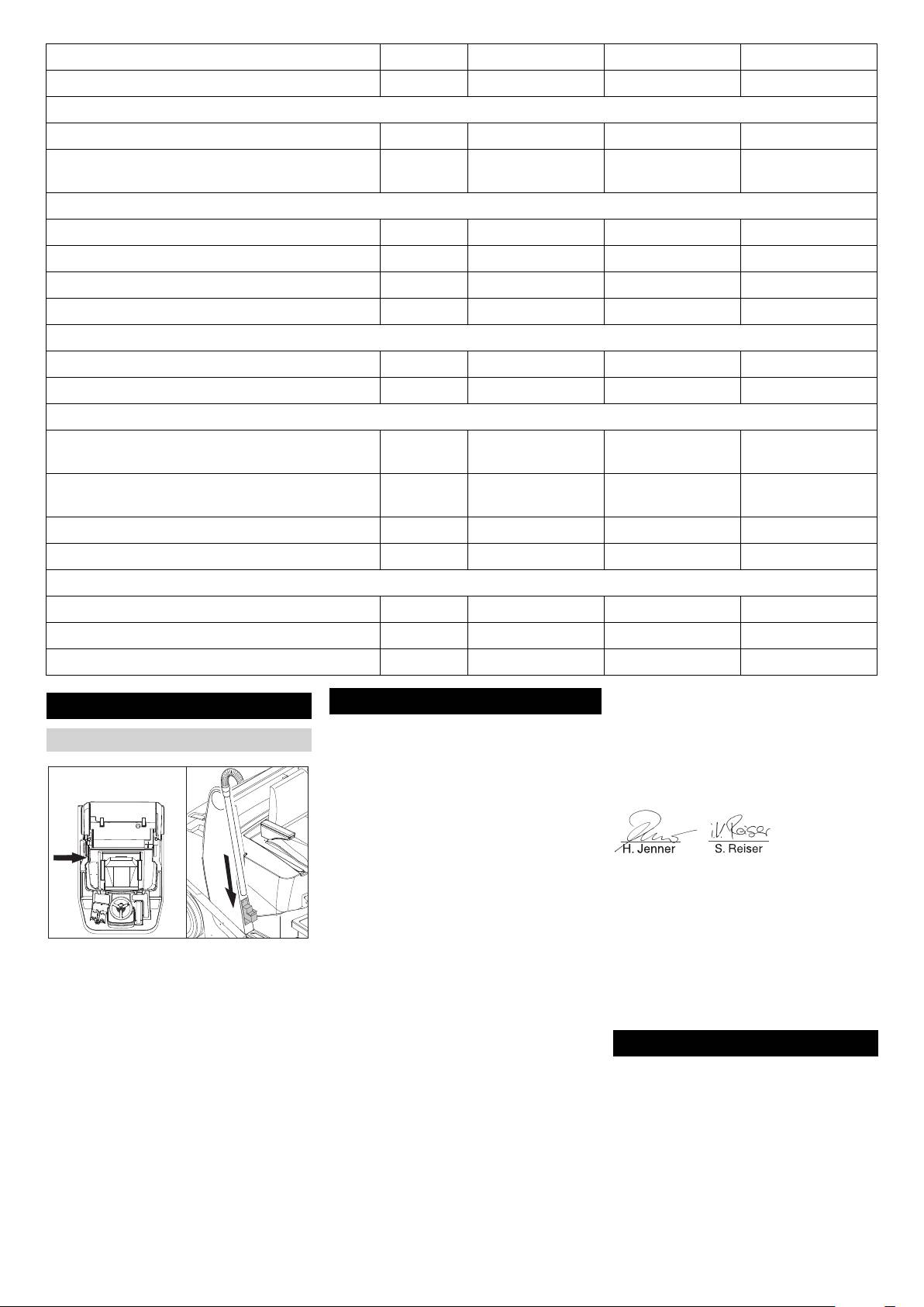
Installation set suction hose
scribed below complies with the relevant
basic safety and health requirements of the
The undersigned act on behalf and under
EU Directives, both in its basic design and
the power of attorney of the company man-
construction as well as in the version put
agement.
into circulation by us. This declaration shall
cease to be valid if the machine is modified
without our prior approval.
CEO
Head of Approbation
Product: Ride-on vacuum sweeper
Type: 1.511-xxx
Authorised Documentation Representative
S. Reiser
Relevant EU Directives
2006/42/EC (+2009/127/EC)
Alfred Kärcher GmbH Co. KG
Remove suction hose from holder.
2004/108/EC
Alfred-Kärcher-Str. 28 - 40
Suck in the dirt.
2000/14/EC
71364 Winnenden (Germany)
Insert the suction hose in the holder.
Applied harmonized standards
Phone: +49 7195 14-0
Note
EN 60335–1
Fax: +49 7195 14-2212
EN 60335–2–72
After completing the suction, ensure that
EN 61000–6–2: 2005
the tube of the suction hose lies on the floor
Warranty
EN 62233: 2008
of the holder.
Applied national standards
The warranty terms published by the rele-
CISPR 12
vant sales company are applicable in each
Applied conformity evaluation method
country. We will repair potential failures of
2000/14/EC: Appendix V
your appliance within the warranty period
Sound power level dB(A)
free of charge, provided that such failure is
KM 120/150 R D
caused by faulty material or defects in man-
Measured: 99
ufacturing. In the event of a warranty claim
Guaranteed: 101
please contact your dealer or the nearest
KM 120/150 R G
authorized Customer Service centre.
Measured: 98
Please submit the proof of purchase.
Guaranteed: 100
38 EN
- 18

Lire ce manuel d'utilisation origi-
Fermer le robinet de carbu-
Risque de basculement en cas de pente la-
nal avant la première utilisation
rant (Seul KM 120/150 R G et
térale trop importante.
de votre appareil, le respecter et le conser-
R D) . . . . . . . . . . . . . . . . FR
. .10
– N'empruntez aucunes pentes supé-
ver pour une utilisation ultérieure ou pour le
Fermer la bouteille à gaz
rieures à 10% dans le sens perpendicu-
(Seul KM 120/150 R LPG) FR
. .10
futur propriétaire.
laire au sens de la marche.
Avant la première mise en service, vous
Transport . . . . . . . . . . . . . . . FR . .10
– Doivent être respectées les mesures de
devez impérativement avoir lu les
Entreposage de l'appareil . . FR . .10
règlement, les règles et les décrets qui
consignes de sécurité N° 5.956-250 !
Entretien et maintenance. . . FR . .10
sont valables pour les automobiles.
Consignes générales . . .
FR
. .10
– L’utilisateur doit utiliser l’appareil de fa-
Table des matières
Nettoyage intérieur du véhi-
çon conforme. Dans la circulation, il doit
cule. . . . . . . . . . . . . . . . . FR
. . 11
prendre en considération les données
Designation de l'appareil. . . FR . . 1
Nettoyage extérieur de l'ap-
locales et lors du maniement de l’appa-
pareil . . . . . . . . . . . . . . . FR
. . 11
Consignes de sécurité . . . . FR . . 1
reil, il doit prendre garde aux tierces
Fréquence de maintenance
. . 11
Consignes générales . .
FR
. . 1
FR
personnes, et en particulier aux en-
Travaux de maintenance
Symboles utilisés sur l'appa-
FR
. . 11
fants.
reil . . . . . . . . . . . . . . . . . FR
. . 2
Assistance en cas de panne FR . .17
– L'appareil doit uniquement être utilisée
Symboles utilisés dans le
par des spécialistes qui sont instruits
Caractéristiques techniques FR . .18
mode d'emploi. . . . . . . . FR
. . 2
dans la manoeuvre ou par des per-
Accessoires . . . . . . . . . . . . . FR . .19
Directives de sécurité pour
sonnes qui peuvent justifiée leur apti-
Lot d'annexe tuyau d'aspira-
des automobiles de gaz li-
tude d'utilisation et qui sont
tion . . . . . . . . . . . . . . . . . FR
. .19
quéfié (Uniquement KM 120/
explicitement mandatées pour l'utilisa-
150 R LPG) . . . . . . . . . . FR
. . 2
Déclaration de conformité CE FR . .19
tion.
Fonction . . . . . . . . . . . . . . . FR . . 3
Garantie. . . . . . . . . . . . . . . . FR . .19
– Ne jamais laisser des enfants ou des
Utilisation conforme . . . . . . FR . . 3
adolescents utiliser l'appareil.
Revêtements appropriés
. . 3
Designation de l'appareil
FR
– La prise de tierce personnes est inter-
Protection de l’environnement FR . . 3
– KM 120/150 R G = Moteur à essence
dit.
Eléments de commande et de
– KM 120/150 R D = Moteur diesel
– Les appareils qu'arrivent en butée mé-
fonction . . . . . . . . . . . . . . . . FR . . 4
– KM 120/150 R LPG = Moteur à gaz
canique ne peuvent être mis seulement
Balayeuses sans cabine de
qu'à partir du siège.
conducteur . . . . . . . . . . FR
. . 4
Pour éviter une utilisation sans droit de
Balayeuses avec cabine de
Consignes de sécurité
l'appareil, la clé de contact doit être re-
conducteur . . . . . . . . . . FR
. . 4
– Cette balayeuse (sans cabine de
tirée.
Repérage de couleur. . .
FR
. . 4
conducteur) doit être utilisée unique-
Pendant le fonctionnement du moteur,
Ouvrir / fermer le capot et sé-
ment sur des surfaces qui présentent
l'appareil doit être tous le temps surveil-
curiser . . . . . . . . . . . . . . FR
. . 5
une pente maximale de 18%.
lée. L'utilisateur ne peut sortir de l'appa-
Pupitre de commande. .
FR
. . 6
– Cette balayeuse (avec cabine de
reil que lorsque le moteur s'arrête,
Avant la mise en service. . . FR . . 7
conducteur) doit être utilisée unique-
l'appareil est assurée contre des mou-
Déchargement de la ma-
ment sur des surfaces qui présentent
vements involontaires, le frein d'arrêt,
chine . . . . . . . . . . . . . . . FR
. . 7
une pente maximale de 10%.
en cas échéant est actionné et la clé de
Déplacement de la ba-
contact est retirée.
layeuse sans autopropulsion FR
. . 7
Consignes générales
Déplacement de la ba-
Machines avec moteur à combustion
Contacter le revendeur en cas de constata-
layeuse sans autopropulsion FR
. . 7
Danger
tion d'une avarie de transport lors du débal-
Mise en service. . . . . . . . . . FR . . 7
lage de l'appareil.
Risque de blessure !
Consignes générales . .
FR
. . 7
– Afin d'assurer un fonctionnement sans
– Le quatrième trou ne peut être fermé.
Faire le plein (Seul KM 120/
danger, observez les avertissements et
– Ne pas se pencher au-dessus ou tou-
150 R G et R D) . . . . . . FR
. . 7
consignes placés sur l'appareil.
cher le quatrième trou (danger de brû-
Monter/changer la bouteille à
– Outre les instructions figurant dans le
lure).
gaz (Seul KM 120/150 R
– Ne pas toucher le moteur de traction
LPG) . . . . . . . . . . . . . . . FR
. . 7
mode d'emploi, il est important de
prendre en considération les consignes
(danger de brûlure).
Travaux de contrôle et de
maintenance . . . . . . . . . FR
. . 8
générales de sécurité et de prévention
– Seul KM 120/150 R LPG: Pour une uti-
contre les accidents imposées par la loi.
lisation de l'appareil dans des locaux
Fonctionnement . . . . . . . . . FR . . 8
fermés, il doit être garanti une ventila-
Réglage du siège du conduc-
Condition de roulage
teur . . . . . . . . . . . . . . . . FR
. . 8
tion suffisante et une évacuation des
Danger
gazes résiduels (danger d'intoxication).
Régler le rétroviseur exté-
Risque de blessure !
rieur (uniquement KM120/
– Les gaz résiduels sont toxiques et no-
150 avec cabine de conduc-
Risque de basculement en cas de pente
cifs, ils ne peuvent être respirés.
teur). . . . . . . . . . . . . . . . FR
. . 8
trop forte.
– Le moteur continue à tourner 3 ou 4 se-
Activer/désactiver l'essuie-
– Dans le sens de la pente, ne rouler que
condes après l'arrêt. Ne pas s'appro-
glace (uniquement KM120/
sur des pentes de moins de 18% (sans
cher de la zone de travail pendant ce
150 avec cabine de conduc-
cabine de conducteur) resp. de 10%
teur). . . . . . . . . . . . . . . . FR
. . 8
laps de temps.
(avec cabine de conducteur).
Choix des programmes.
FR
. . 8
Balayeuses avec cabine de conducteur
Risque de basculement en cas de conduite
Démarrage de la machine
FR
. . 8
rapide dans les virages.
Remarque
Déplacer la balayeuse. .
FR
. . 9
– Roulez lentement dans les virages.
La cabine de conducteur ne constitue
Balayage . . . . . . . . . . . .
FR
. . 9
Risque de basculement en cas de sol ins-
qu'une protection contre les intempéries,
elle n'est pas un toit de sécurité ou une pro-
Vider le bac à poussières
FR
. . 9
table.
– N'utilisez la machine que sur des sols
tection contre les tonneaux.
Mise hors service de l'appa-
reil . . . . . . . . . . . . . . . . . FR
. 10
stabilisés.
Danger
Remisage . . . . . . . . . . . . . . FR . 10
- 1
39FR

Les portes en plastique de la cabine du
bouteille à l'autre. Avec cela, la bou-
Directives de sécurité pour des au-
conducteur sont dotées de fentes d'aéra-
teille surchargée est, après la fermeture
tomobiles de gaz liquéfié (Unique-
tion. Celles-ci doivent impérativement res-
de la valve de la bouteille (compare B.
ment KM 120/150 R LPG)
ter libres pour assurer une aération
1de cette directive), exposée à une
suffisante.
Association principale de l'organisation
augmentation de pression inadmis-
professionnelle industrielle. Les gazes li-
sible.
Danger de trouble au-
quéfié (les gazes carburant) sont butane et
– Lorsque la mention pour la position cor-
ditif. À l'utilisation de
propane ou mélanges de butane/propane.
recte de la bouteilles est "en haut", la
l'appareil utiliser abso-
Sont livrés dans des bouteilles spéciales.
pose de la bouteille pleine est réussit (le
lument un protecteur
La pression de marche de ces gazes dé-
raccord de connexion indique verticale-
d'oreille approprié.
pende de la température extérieure.
ment en haut).
Danger
Procéder avec soin au remplacement des
bouteilles de gaz. Lors du montage et du
Risque d'explosion ! Ne pas traiter le gaz
Accessoires et pièces de rechange
démontage, la tubulure de sortie du gaz de
liquéfié comme l'essence. L'essence s'éva-
– Utiliser uniquement des accessoires et
la valve de la bouteille doit être étanchéi-
pore lentement et le gaz liquéfié passe im-
des pièces de rechange autorisés par le
fiée avec un écrou de verrouillage serré
médiatement à l'état gazeux. Le danger de
fabricant. Des accessoires et des
avec une clé.
gazéification du local et d'inflammation est
pièces de rechange d’origine garan-
– Les bouteilles à gaz non étanche ne
bien supérieur avec le gaz liquéfie qu'avec
tissent un fonctionnement sûr et parfait
doivent plus être utilisée. Elles doivent
l'essence.
de l’appareil.
être immédiatement vidée à l'air, selon
– Une sélection des pièces de rechange
Danger
tous les mesures de précaution, et en-
utilisées le plus se trouve à la fin du
Risque de blessure ! Utiliser uniquement
suite, elle doivent être caractérisée
mode d'emploi.
des bouteilles de gaz liquide avec carbu-
comme non étanche. Lorsque les bou-
– Vous trouverez plus d'informations sur
rant gazeux selon DIN 51622 de la qualité
teilles à gaz sont endommagées à la
les pièces de rechange dans le menu
A ou B, en fonction de la température am-
délivrance ou quand quelqu'un viet les
Service du site www.kaercher.com.
biante.
chercher, le dommage doit être signalé
PRÉCAUTION
immédiatement au loueur ou à son ré-
Symboles utilisés sur l'appareil
Gaz de ville est principiellement inderdit.
presentant (pompiste ou ce genre).
Pour le moteur à gaz sont autorisés des
– Avant de brancher la bouteille à gaz, la
Surfaces brûlantes,
mélanges de gaz liquéfié composant de
tubulure de raccordement doit être véri-
risque de brûlure!
propane/butane, où le rapport de mélange
fiée si elle est en bon état.
Avant d'effectuer toute
se trouve entre 90/10 jusqu'à 30/70. Pour
– Après le raccordement de la bouteille,
opération sur l'appa-
obtenir un meilleur résultat au démarrage à
celle-ci doit être vérifiée à sa étanchéité
reil, laisser refroidir
froid, utiliser, avec une température exté-
à l'aide des liquides d'écume.
suffisamment le sys-
rieure au-dessous de 0 °C (32 °F), en prio-
– Les valves doivent être ouvertes lente-
tème d'échappement.
rité du gaz liguéfié avec un haut
ment. L'ouverture ou la fermeture ne
pourcentage de propane, parce que l'éva-
peut être effectuées qu'à avec des ou-
Symboles utilisés dans le mode
porisation se réalise déjà avec des tempé-
tils de choc.
d'emploi
ratures basses .
– En cas des incendies de gaz liquéfié,
DANGER
Devoirs de la direction et des travail-
utiliser uniquement des extincteurs à
leurs
Pour un danger immédiat qui peut avoir
poudre d'acide carbonique.
pour conséquence la mort ou des bles-
– Toutes les personnes qui travailleront
– Toute la machine à gaz liquéfié doit être
sures corporelles graves.
avec du gaz liquéfié sont obligées de
en permanence vérifiée de son état
prendre connaissance sur le caractére
fonctionnelle, en particulier de son
몇 AVERTISSEMENT
particulier des gazes liquéfiés pour la
étanchéité. L'utilisation du véhicule
Pour une situation potentiellement dange-
réalisation sans risque de l'exploitation.
avec un dispositif à gaz non étanche est
reuse qui peut avoir pour conséquence des
Le manuel présent doit être toujours
interdit.
blessures corporelles graves ou la mort.
avec la balayeuse.
– Avant l'extinction du raccord de tube
PRÉCAUTION
Maintenance doit être fait par un spécia-
respectivement du raccord pour tuyau
Pour une situation potentiellement dange-
liste
flexible, la valve de la bouteille doit être
reuse qui peut avoir pour conséquence des
– Les machines à gaz carburant doivent
fermée. Pour éviter que le gaz sous
blessures légères ou des dommages maté-
être vérifiées à des périodes régulières,
pression, qui se trouve encore dans la
riels.
au moins une fois par an, par un spécia-
tuyauterie, s'échappe spontanément,
liste afin de vérifier la capacité de fonc-
l'écrou de raccord d'entrée à la bouteille
tionnement et à la étanchéité (selon
doit être déserré lentement et seule-
BGG 936).
ment un peu.
– La révision doit être confirmée par écrit.
– Si le gaz est pris d'un récipient de
La révision se fonde sur le § 33 et le §
grande capacité, les règlement à ce
37 de la OLAA "Utilisation de gaz liqué-
titre doivent être demandés au distribu-
fié" (BGV D34).
teur de grand capacité correspondant
de gaz liquéfié.
– La révision des véhicules à gaz liquéfié
se fonde sur les directives du ministre
Danger
de transport.
Risque de blessure !
– Le gaz liquéfié en moule liquide pro-
Mise en service/Fonctionnement
voque sur la peau des engelures.
– Le prélèvement de gaz d'échappement
se fait uniquement d'une bouteille. Le
– Après le démontage, l'écrou de ver-
prélèvement de gaz d'échappement de
rouillage doit être vissé à fond sur le fi-
plusieurs bouteilles peut provoqué le
letage de raccord d'entrée de la
passage du gaz liquéfié passe d'une
bouteille.
40 FR
- 2
