Karcher HDS 10-20 4 M 3X220 – страница 2
Инструкция к Системе Водяного Охлаждения Karcher HDS 10-20 4 M 3X220

Technische Daten
HDS 7/9 HDS 7/10 HDS 7/12
Netzanschluss
Spannung V 100 240 230
Stromart Hz 1~ 50 1~ 50 1~ 50
Anschlussleistung kW 3,2 3,1 3,4
Schutzart -- IPX5 IPX5 IPX5
Schutzklasse -- I I I
Absicherung (träge) A 35 16 16
Maximal zulässige Netzimpedanz Ohm -- -- (0,321+ j0,200)
Wasseranschluss
Zulauftemperatur (max.) °C 30 30 30
Zulaufmenge (min.) l/h (l/min) 1000 (16,7) 1000 (16,7) 1000 (16,7)
Saughöhe aus offenem Behälter (20 °C) m 0,5 0,5 0,5
Zulaufdruck (max.) MPa (bar) 0,6 (6) 0,6 (6) 0,6 (6)
Leistungsdaten
Fördermenge Wasser l/h (l/min) 350-700 (5,8-
350-700 (5,8-
350-700 (5,8-
11,6)
11,6)
11,6)
Arbeitsdruck Wasser (mit Standarddüse) MPa (bar) 3-9 (30-90) 3-10 (30-100) 3-12 (30-120)
Max. Betriebsüberdruck (Sicherheitsventil) MPa (bar) 12 (120) 13 (130) 15 (150)
Fördermenge Dampfbetrieb l/h (l/min) 330-350 (5,5-
330-350 (5,5-
330-350 (5,5-
5,8)
5,8)
5,8)
Max. Arbeitsdruck Dampfbetrieb (mit Dampfdü-
MPa (bar) 3,2 (32) 3,2 (32) 3,2 (32)
se)
Teile-Nr. Dampfdüse -- 2.885-119.0 2.885-119.0 2.885-039.0
Max. Arbeitstemperatur Heißwasser °C 98 98 98
Arbeitstemperatur Dampfbetrieb °C 155 155 155
Reinigungsmittelansaugung l/h (l/min) 0-45 (0-0,75) 0-45 (0-0,75) 0-45 (0-0,75)
Brennerleistung kW 58 58 58
Maximaler Heizölverbrauch kg/h 4,6 4,6 4,6
Rückstoßkraft der Handspritzpistole (max.) N 13,5 17,9 17,9
Düsengröße (MX/SX) -- 060 (060) 054 (055) 047 (047)
Ermittelte Werte gemäß EN 60335-2-79
Geräuschemission
Schalldruckpegel L
pA
dB(A) 70 70 70
Unsicherheit K
pA
dB(A) 2 2 2
Schallleistungspegel L
WA
+ Unsicherheit K
WA
dB(A) 88 88 88
Hand-Arm Vibrationswert
2
Handspritzpistole m/s
1,1 1,1 1,1
2
Strahlrohr m/s
3,4 3,4 3,4
2
Unsicherheit K m/s
1,0 1,0 1,0
Betriebsstoffe
Brennstoff -- Heizöl EL oder
Heizöl EL oder
Heizöl EL oder
Diesel
Diesel
Diesel
Ölmenge l 0,75 0,75 0,75
Ölsorte -- 0W40 0W40 0W40
Maße und Gewichte
Länge x Breite x Höhe mm 1330 x 750 x
1330 x 750 x
1330 x 750 x
1060
1060
1060
Typisches Betriebsgewicht, M/S kg 165 167 165
Typisches Betriebsgewicht, MX/SX kg 170 172 170
Brennstofftank l 25 25 25
Reinigungsmitteltank l 10+20 10+20 10+20
– 15
21DE

HDS 8/18
Netzanschluss
Spannung V 230 400
Stromart Hz 3~ 50 3~ 50
Anschlussleistung kW 5,5 5,5
Schutzart -- IPX5 IPX5
Schutzklasse -- I I
Absicherung (träge) A 25 16
Maximal zulässige Netzimpedanz Ohm --
Wasseranschluss
Zulauftemperatur (max.) °C 30
Zulaufmenge (min.) l/h (l/min) 1100 (18,3)
Saughöhe aus offenem Behälter (20 °C) m 0,5
Zulaufdruck (max.) MPa (bar) 0,6 (6)
Leistungsdaten
Fördermenge Wasser l/h (l/min) 400-800 (6,7-13,3)
Arbeitsdruck Wasser (mit Standarddüse) MPa (bar) 3-18 (30-180)
Max. Betriebsüberdruck (Sicherheitsventil) MPa (bar) 20,5 (205)
Fördermenge Dampfbetrieb l/h (l/min) 340-400 (5,6-6,7)
Max. Arbeitsdruck Dampfbetrieb (mit Dampfdüse) MPa (bar) 3,2 (32)
Teile-Nr. Dampfdüse -- 2.885-119.0
Max. Arbeitstemperatur Heißwasser °C 98
Arbeitstemperatur Dampfbetrieb °C 155
Reinigungsmittelansaugung l/h (l/min) 0-50 (0-0,8)
Brennerleistung kW 67
Maximaler Heizölverbrauch kg/h 5,3
Rückstoßkraft der Handspritzpistole (max.) N 24,3
Düsengröße (MX/SX) -- 043 (043)
Ermittelte Werte gemäß EN 60335-2-79
Geräuschemission
Schalldruckpegel L
pA
dB(A) 71
Unsicherheit K
pA
dB(A) 2
Schallleistungspegel L
WA
+ Unsicherheit K
WA
dB(A) 88
Hand-Arm Vibrationswert
2
Handspritzpistole m/s
1,0
2
Strahlrohr m/s
3,4
2
Unsicherheit K m/s
1,0
Betriebsstoffe
Brennstoff -- Heizöl EL oder Diesel
Ölmenge l 0,75
Ölsorte -- SAE 90
Maße und Gewichte
Länge x Breite x Höhe mm 1330 x 750 x 1060
Typisches Betriebsgewicht, M/S kg 165
Typisches Betriebsgewicht, MX/SX kg 170
Brennstofftank l 25
Reinigungsmitteltank l 10+20
22 DE
– 16

HDS 9/18 HDS 10/20 HDS 12/18
Netzanschluss
Spannung V 230 400 230 400 230 400
Stromart Hz 3~ 50 3~ 50 3~ 50 3~ 50 3~ 50 3~ 50
Anschlussleistung kW 6,4 6,4 7,8 7,8 8,4 8,4
Schutzart -- IPX5 IPX5 IPX5 IPX5 IPX5 IPX5
Schutzklasse -- I I I I I I
Absicherung (träge) A 25 16 25 16 35 16
Maximal zulässige Netzimpedanz Ohm -- (0,169+ j0,105) (0,163+ j0,102)
Wasseranschluss
Zulauftemperatur (max.) °C 30 30 30
Zulaufmenge (min.) l/h (l/min) 1200 (20) 1300 (21,7) 1500 (25)
Saughöhe aus offenem Behälter (20 °C) m 0,5 0,5 0,5
Zulaufdruck (max.) MPa (bar) 0,6 (6) 0,6 (6) 0,6 (6)
Leistungsdaten
Fördermenge Wasser l/h (l/min) 450-900 (7,5-15) 500-1000 (8,3-
600-1200 (10-
16,7)
20)
Arbeitsdruck Wasser (mit Standarddüse) MPa (bar) 3-18 (30-180) 3-20 (30-200) 3-18 (30-180)
Max. Betriebsüberdruck (Sicherheitsventil) MPa (bar) 21,5 (215) 24 (240) 21,5 (215)
Fördermenge Dampfbetrieb l/h (l/min) 390-450 (6,5-
460-505 (7,6-
550-610 (9,1-
7,5)
8,4)
10,1)
Max. Arbeitsdruck Dampfbetrieb (mit Dampfdü-
MPa (bar) 3,2 (32) 3,2 (32) 3,2 (32)
se)
Teile-Nr. Dampfdüse -- 2.885-040.0 2.885-041.0 2.885-120.0
Max. Arbeitstemperatur Heißwasser °C 98 98 98
Arbeitstemperatur Dampfbetrieb °C 155 155 155
Reinigungsmittelansaugung l/h (l/min) 0-54 (0-0,9) 0-60 (0-1) 0-72 (0-1,2)
Brennerleistung kW 75 83 100
Maximaler Heizölverbrauch kg/h 5,8 6,4 7,7
Rückstoßkraft der Handspritzpistole (max.) N 28,2 33,0 37,6
Düsengröße (MX/SX) -- 050 (050) 054 (054) 068 (070)
Ermittelte Werte gemäß EN 60335-2-79
Geräuschemission
Schalldruckpegel L
pA
dB(A) 71 73 73
Unsicherheit K
pA
dB(A) 2 2 2
Schallleistungspegel L
WA
+ Unsicherheit K
WA
dB(A) 88 90 90
Hand-Arm Vibrationswert
2
Handspritzpistole m/s
1,0 1,2 1,5
2
Strahlrohr m/s
3,6 5,2 4,8
2
Unsicherheit K m/s
1,0 1,0 1,0
Betriebsstoffe
Brennstoff -- Heizöl EL oder
Heizöl EL oder
Heizöl EL oder
Diesel
Diesel
Diesel
Ölmenge l 0,75 1,0 1,0
Ölsorte -- SAE 90 SAE 90 SAE 90
Maße und Gewichte
Länge x Breite x Höhe mm 1330 x 750 x
1330 x 750 x
1330 x 750 x
1060
1060
1060
Typisches Betriebsgewicht, M/S kg 165 175 192
Typisches Betriebsgewicht, MX/SX kg 170 182 197
Brennstofftank l 25 25 25
Reinigungsmitteltank l 10+20 10+20 10+20
– 17
23DE

Wiederkehrende Prüfungen
Hinweis: Die Prüffristempfehlungen entsprechend der jeweiligen nationalen Anforderun-
gen des Betreiberlandes sind zu beachten.
Prüfung durchge-
Äußere Prüfung Innere Prüfung Festigkeitsprü-
führt durch:
fung
Name Unterschrift der be-
Unterschrift der be-
Unterschrift der be-
fähigten Person/
fähigten Person/
fähigten Person/
Datum
Datum
Datum
Name Unterschrift der be-
Unterschrift der be-
Unterschrift der be-
fähigten Person/
fähigten Person/
fähigten Person/
Datum
Datum
Datum
Name Unterschrift der be-
Unterschrift der be-
Unterschrift der be-
fähigten Person/
fähigten Person/
fähigten Person/
Datum
Datum
Datum
Name Unterschrift der be-
Unterschrift der be-
Unterschrift der be-
fähigten Person/
fähigten Person/
fähigten Person/
Datum
Datum
Datum
Name Unterschrift der be-
Unterschrift der be-
Unterschrift der be-
fähigten Person/
fähigten Person/
fähigten Person/
Datum
Datum
Datum
Name Unterschrift der be-
Unterschrift der be-
Unterschrift der be-
fähigten Person/
fähigten Person/
fähigten Person/
Datum
Datum
Datum
24 DE
– 18
Please read and comply with
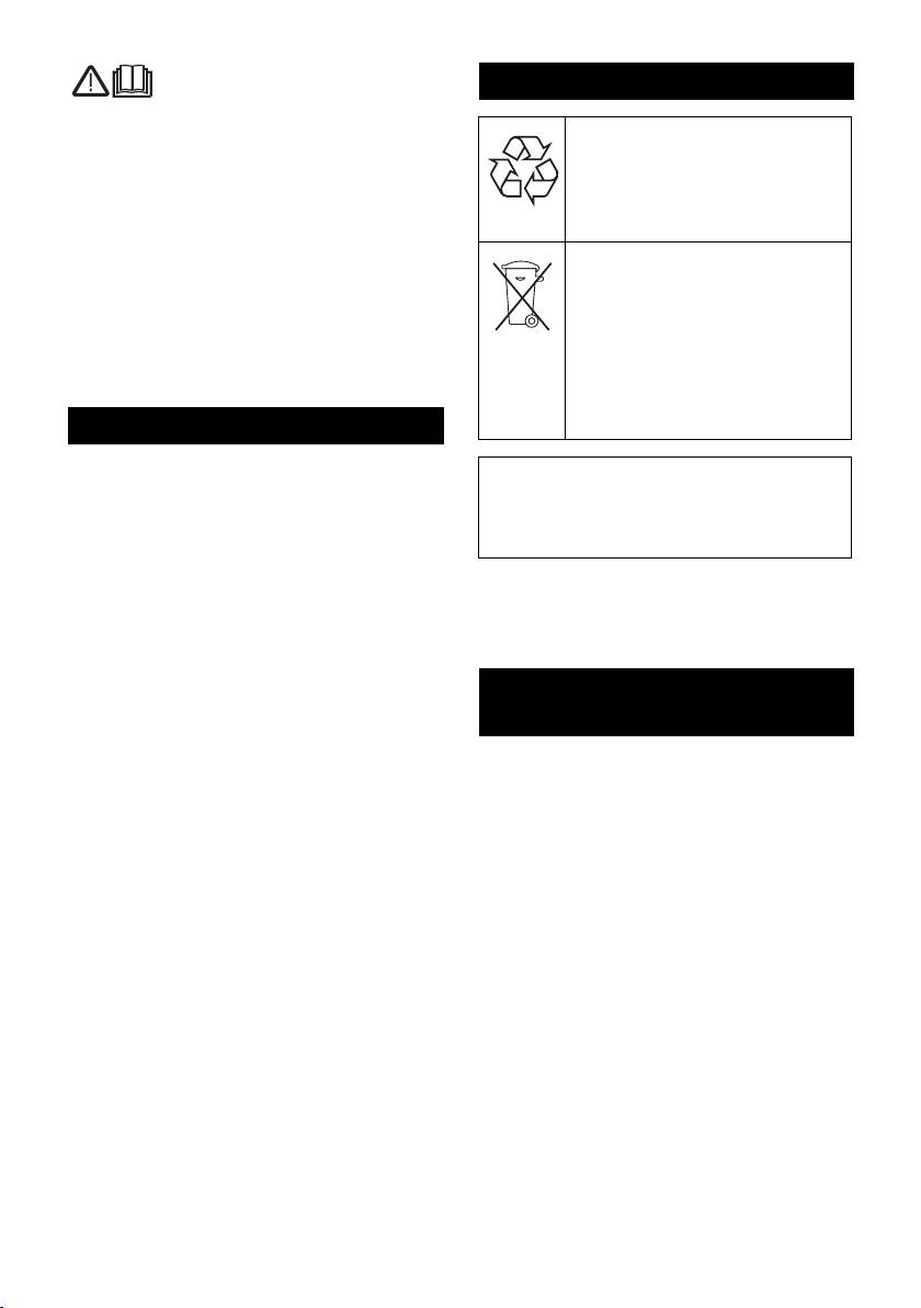
Environmental protection
these original instructions prior
to the initial operation of your appliance and
The packaging material can be
store them for later use or subsequent own-
recycled. Please do not throw
ers.
the packaging material into
– Before first start-up it is definitely nec-
household waste; please send it
essary to read the operating instruc-
for recycling.
tions and safety indications Nr. 5.951-
Old appliances contain valuable
949.0!
materials that can be recycled;
– In case of transport damage inform ven-
these should be sent for recy-
dor immediately
cling. Batteries, oil, and similar
– Check the contents of the pack before
substances must not enter the
unpacking. For scope of delivery see il-
environment. Please dispose of
lustration 1.
your old appliances using ap-
Contents
propriate collection systems.
Environmental protection . . EN . . .1
Please do not release engine oil, fuel oil,
diesel and petrol into the environment Pro-
Symbols in the operating in-
structions . . . . . . . . . . . . . . EN . . .1
tect the ground and dispose of used oil in
Overview . . . . . . . . . . . . . . EN . . .2
an environmentally-clean manner.
Symbols on the machine . . EN . . .3
Notes about the ingredients (REACH)
Proper use . . . . . . . . . . . . . EN . . .3
You will find current information about the
Safety instructions . . . . . . . EN . . .3
ingredients at:
Safety Devices . . . . . . . . . . EN . . .3
www.kaercher.com/REACH
Start up. . . . . . . . . . . . . . . . EN . . .4
Symbols in the operating
Operation . . . . . . . . . . . . . . EN . . .6
instructions
Storage. . . . . . . . . . . . . . . . EN . .10
Transport . . . . . . . . . . . . . . EN . .10
Danger
Maintenance and care . . . . EN . .10
Immediate danger that can cause severe
Troubleshooting . . . . . . . . . EN . .11
injury or even death.
Warranty. . . . . . . . . . . . . . . EN . .13
몇 Warning
Accessories and Spare Parts EN . .13
Possible hazardous situation that could
EC Declaration of Conformity EN . .14
lead to severe injury or even death.
Technical specifications . . . EN . .15
Caution
Recurring tests . . . . . . . . . . EN . .18
Possible hazardous situation that could
lead to mild injury to persons or damage to
property.
– 1
25EN

33 Oil tank
Overview
34 Pressure/quantity regulation of the
pump unit
Device elements
35 Oil drain screw
Figure 1
36 Backflow valve of the detergent infeed
1 Cover
37 Detergent suction hose 1 with filter
2 Support for spray lance
38 Detergent suction hose 2 with filter
(both sides)
39 Fuel filter
3 System care Advance RM 110/RM 111
40 Service switch
4 Steering roller with fixed position brake
41 Water shortage safe guard with sieve
5 Mounting location for transport
42 Float tank
(both sides)
43 Fine filter (water)
6 Wheel
Operating field
7 Water supply set
8 High pressure connection
Figure 2
(M/S only)
A Power switch
9 O-ring set (for replacement)
B Temperature controller
10 High pressure hose
C Dosage valve for detergent
11 Hand spray gun
D Manometer
12 Spray lance
1 Indicator lamp pump
13 High-pressure nozzle (stainless steel)
2 Indicator lamp rotation direction
14 Steam nozzle (brass)
(not HDS 7/9, HDS 7/10, HDS 7/12)
15 Pressure/ quantity regulation at the
3 “Ready for use” indicator lamp
hand spray gun
4 Fuel indicator lamp
16 Safety latch of the hand spray gun
5 Indicator lamp: Detergent 1
17 Power supply
(HDS 12/18 only)
18 Folding compartment
6 Engine indicator lamp
(M/S only)
7 Indicator lamp burner failure
19 Connection for water supply with filter
8 Indicator lamp service
20 Exit opening of the high-pressure hose
9 Indicator lamp system care
(MX/SX only)
10 Indicator lamp: Detergent 2
21 Step depression
(HDS 12/18 only)
22 Pouring vent for detergent 2
Colour coding
23 Hand crank for hose drum
– The operating elements for the cleaning
(MX/SX only)
process are yellow.
24 Pouring vent for detergent 1
– The controls for the maintenance and
25 Hose drum
service are light gray.
(MX/SX only)
26 Pouring vent for fuel
27 Handle
28 Operating field
29 Closing flap for storage compartment
30 Storage compartment for accessories
31 Nameplate
32 Cover lock
26 EN
– 2
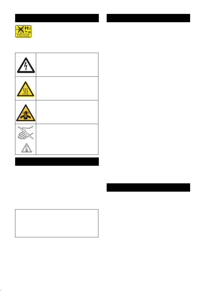
Symbols on the machine
Safety instructions
High-pressure jets can be dan-
– Please follow the national rules and
gerous if improperly used. The
regulations for fuel spray jets of the re-
jet may not be directed at per-
spective country.
sons, animals, live electrical equipment or
– Please follow the national rules and
at the appliance itself.
regulations for accident prevention of
the respective country. Fuel spray jets
Risk of electric shock!
must be tested regularly and the results
Only electricians or authorised
of these tests must be documented in
technicians are permitted to
writing.
work on parts of the plant.
– The heating appliance of the machine is
Risk of burns on account of hot
an ignition plant. All national laws and
surfaces!
regulations about heating systems must
also be followed.
– As per the applicable national guide-
Risk of poisoning! Do not
lines, the first time this high-pressure
breathe in the exhaust fumes.
cleaner must be taken into operation by
a skilled person. KÄRCHER has al-
ready performed this initial start-up for
you and has documented it accordingly.
Risk of injury! Do not reach in.
The documentation can be requested at
your KÄRCHER partner. Please have
the part and plant number of the appli-
ance available when enquiring about
the documentation.
– We would like to point out that the appli-
Proper use
ance must be repeatedly checked by a
skilled person as prescribed by the ap-
Cleaning of: Machines, Vehicles, Struc-
plicable national regulations. Please
tures, Tools, Facades, Terraces, Garden-
contact your KÄRCHER partner.
ing tools, etc.
Danger
Safety Devices
Risk of injury! Follow the respective safety
Safety devices serve for the protection of
regulations when operating at gas stations
the user and must not be put out of opera-
or other dangerous areas.
tion or bypassed with respect to their func-
Please do not let mineral oil contaminated
tion.
waste water reach soil, water or the sew-
age system. Perform engine cleaning and
bottom cleaning therefore only on speci-
fied places with an oil trap.
– 3
27EN

Overflow valve with two pressure
Installing the handle
switches
Figure 3
– While reducing the water supply at the
Caution
pump head or with the Servopress -
Hook the electric supply line into the cable
regulation the overflow valve opens and
guide of the right handle bow. Ensure that
part of the water flows back to the pump
the cable is not damaged.
suck side.
Replace the system care bottle
– If the hand-spray gun is closed, so that
the whole water flows back to the pump
Note: Push the bottle in securely to pene-
suck side, the pressure switch at the
trate the closure. Do not remove bottle until
overflow valve shuts down the pump.
it is empty.
– If the hand spray gun is opened, the
Note: To protect the device, the burner is
pressure switch on the cylinder head
switched off 5 hours after the system care
turns the pump back on.
bottle is empty.
The overflow valve is set by the manufac-
– The system care prevents the calcifica-
tion of the heating spiral while operating
turer and sealed. Setting only by customer
with calciferous tap water. It is dosed
service.
into the supply in the float container
Safety valve
drop by drop.
– The metering is set to medium water ri-
– The safety valve opens, when the over-
gidity by the manufacturer
flow valve resp. the pressure switch is
Note: A system care bottle is included in
broken.
the delivery.
The safety valve is set by the manufacturer
Replace the system care bottle.
and sealed. Setting only by customer ser-
vice.
Adjusting the dosage of the system
care Advance RM 110/RM 111
Water shortage safeguard
Determining the hardness of tap water:
– The water shortage safeguard prevents
the burner to be turned on when there is
– through the public water supply works,
water shortage.
– using a hardness tester (order no.
– A sieve prevents the contamination of
6.768-004)
the safeguard and must be cleaned reg-
Water hard-
Scale on the service switch
ular.
ness (°dH)
Temperature stop for exhaust gases
<3 OFF (no dosing)
3...7 1
– The temperature stop switches off the
machine when the waste gases have
7...14 2
reached very high temperatures.
14...21 3
>21 4
Start up
Set the service switch according to the
몇 Warning
water hardness in the table.
Risk of injury! Device, tubes, high pressure
Note: Observe the following when using
hose and connections must be in faultless
system care Advance 2 RM 111:
condition. Otherwise, the appliance must
– Calcification protection: See table
not be used.
Lock parking brake.
– Pump care and black water protection:
Set the service switch to at least setting 3.
28 EN
– 4

Caution
Refill fuel
Always unwind high pressure hose com-
Danger
pletely
Risk of explosion! Only refill diesel oil or
Installing the replacement
light fuel oil. Unsuitable fuels, e.g. petrol,
high-pressure hose (appliances
are not to be used.
without hose drum)
Caution
Figure 5
Never operate device with empty fuel tank
The fuel pump will otherwise be destroyed.
Installing the replacement
Refill fuel.
high-pressure hose (appliances
Close tank lock.
with hose drum)
Wipe off spilled fuel.
Figure 6
Refill detergent
Completely roll off the high-pressure
hose from the hose drum.
Caution
Rotate the hose drum until the screwed-
Risk of injury!
on semi bowl is pointing toward the top.
– Use Kärcher products only.
Loosen all three screws and remove the
– Under no circumstances fill solvents
loosened semi bowl.
(petrol, aceton, diluting agent etc.)
Figure 7
– Avoid eye and skin contact.
Unlatch the fastening clamp for the
– Observe safety and handling instruc-
high-pressure hose and pull the hose
tions by the detergent manufacturer.
out.
Kärcher offers an individual cleaning
Route the new high-pressure hose
and care appliances program.
through the intended hose guide and
Your dealer will consult you gladly.
the deflection pulley at the bottom of the
Refill detergent.
appliance.
Install the hand-spray gun, the jet
Slide the hose nipple all the way into the
pipe, the nozzle and the high
knot section of the hose drum and se-
cure with the fastening clamp.
pressure hose
Replace the half bowl.
Figure 4
Connect ray tube with hand spray gun
Water connection
Tighten the screw connection of the
For connection values refer to technical
spray lance finger tight.
specifications
Insert high pressure nozzle into cover-
Attach supply hose (minimum length
ing nut
7.5 m, minimum diameter 3/4“) to the
Install covering nut and tighten firmly
water supply set by means of a hose
Appliance without hose drum:
clamp.
Connect the high pressure hose to the
Connect the supply hose to the water
high pressure connection point of the
connection point of the machine and at
machine.
the water supply point (for e.g. a tap).
Device with hose drum:
Note: The supply hose and the hose clamp
Connect high pressure hose to hand
are not included in the scope of delivery.
spray gun
– 5
29EN

Suck in water from vessel Power connection
If you want to suck in water from an exter-
– For connection values, see technical
nal vessel, the following modification is
data and type plate.
necessary:
– The electrical connections must be
Figure 8
done by an electrician according to IEC
Remove the system care bottle.
60364-1.
Release and remove the cover of the
Danger
system care.
Danger of injury by electric shock.
Remove water connection from the fine
– Unsuitable electrical extension cables
filter.
can be hazardous. Only use electrical
Unscrew the fine filter from the pump
extension cables outdoors which have
head.
been approved and labelled for this pur-
Figure 9
pose and have an adequate cable
Remove the system care reservoir.
cross-section.
Unscrew the top supply hose to the
– Always unwind extension lines com-
swimmer container.
pletely.
Figure 10
– The plug and coupling of the extension
Connect the top supply hose at pump
cable used must be watertight.
head.
Caution
Replug the rinse line of the detergent
The highest allowed net impedance at the
dosing valve.
electrical connection point (refer to techni-
Connect suction hose (minimum diame-
cal data) is not to be exceeded. In case of
ter 3/4“) with filter (accessory) to the
confusion regarding the power impedance
water connection point.
present on your connection, please contact
– Max. suck height: 0.5 m
your utilities provider.
Until the pump sucked in water, you should:
Operation
Set the pressure/quantity regulation at
the pump unit to maximum quantity.
Danger
Close the dosing valve for the detergent.
Risk of explosion!
Danger
Do not spray flammable liquids.
Never suck in water from a drinking water
Danger
container. Never suck in liquids which con-
Risk of injury! Never use the appliance
tain solvents like lacquer thinner, petrol, oil
without the spray lance attached. Check
or unfiltered water. The sealings within the
and ensure proper fitting of the spray lance
device are not solvent resistant. The spray
prior to each use. The screw connection of
mist of solvents is highly inflammable, ex-
the spray lance must be fingertight.
plosive and poisonous.
Caution
Note: Assembly in reverse order. Ensure
Never operate device with empty fuel tank
that the solenoid valve cable on the reser-
The fuel pump will otherwise be destroyed.
voir of the system care is not pinched.
30 EN
– 6
Safety instructions
Turning on the Appliance
몇 Warning
Set appliance switch to desired operat-
ing mode.
Long hours of using the appliance can
Indicator lamp for operational readiness
cause circulation problems in the hands on
lights up.
account of vibrations.
It is not possible to specify a generally valid
The device starts briefly and turns off, as
operation time, since this depends on sev-
soon as the working pressure is reached.
eral factors:
Note: If the indicator lamps for pump, rota-
– Proneness to blood circulation deficien-
tion direction, burner malfunction or engine
cies (cold, numb fingers).
are on during operation, turn off the appli-
ance immediately and repair malfunction,
– Low ambient temperature. Wear warm
refer to "Help with malfunctions".
gloves to protect hands.
Release the trigger gun.
– A firm grip impedes blood circulation.
When activating the hand spray gun the de-
– Continuous operation is worse than an
vice switches back on.
operation interrupted by pauses.
Note: If no water comes out of the high
In case of regular, long-term operation of
pressure nozzle, vent pump. Refer to "Help
the device and in case of repeated occur-
with malfunctions - appliance is not building
rence of the symptoms (e.g. cold, numb fin-
up pressure".
gers) please consult a physician.
Adjust cleaning temperature
Replace the nozzle
Set temperature regulator to desired
Danger
temperature.
Switch the appliance off prior to replacing
30 °C to 98 °C
nozzle and activate hand spray gun until
– Clean with hot water.
device is pressureless.
100 °C to 150 °C
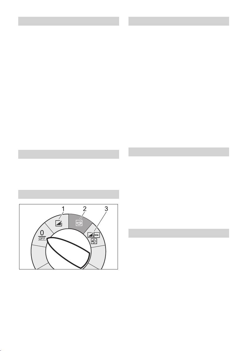
Operating modes
– Clean using steam.
Replace the high-pressure nozzle
(stainless steel) with steam nozzle
(brass), (refer to "Using steam").
Set working pressure and flow rate
Pressure/quantity regulation of the
pump unit
Turn the regulation spindle in a clock-
wise direction: Increase working pres-
sure (MAX).
0/OFF =Off
Turn the regulation spindle in an anti-
1 Operating with cold water
clockwise direction: Reduce working
2 Eco operation (hot water max. 60 °C)
pressure (MIN).
3 Operating with hot water/steam
– 7
31EN

Pressure/ quantity regulation at the
Operating with cold water
hand spray gun
Removal of light contaminations and clear
Set thermostat to max. 98 °C.
rinse, i.e.: Gardening tools, terrace, tools,
Set the operating pressure on the pump
etc.
unit to the maximum value.
Set operating pressure according to
Set the working pressure and feed
need.
quantity by turning (steplessly) the
pressure/quantity regulation mecha-
Eco operation
nism at the hand spray gun (+/-).
The appliance works in the most economi-
Danger
cal temperature range.
When adjusting the pressure/quantity regu-
Note: The temperature can be regulated
lation, make sure that the screw connection
up to 60 °C.
of the spray lance does not become loose.
Operating with hot water/steam
Note: For long term work with low pres-
sure, set pressure at the pump unit.
We recommend the following cleaning tem-
peratures:
Operation with detergent
– Light contaminations
– For considerate treatment of the envi-
30-50 °C
ronment use detergent economically.
– Contaminations containing protein, i.e.
– The detergent must be suitable for the
in the food processing industry
surface to be cleaned.
max. 60 °C
With support of the detergent dose
– Vehicle cleaning, machine cleaning
valve set detergent concentration as
60-90 °C
determined by the manufacturer.
– De-preserve, contaminations contain-
Note: Recommended values at the control
ing strong fat contents
panel at maximum working pressure.
100-110 °C
Cleaning
– De-frosting of surcharge substances,
partially facade cleaning
Set pressure/temperature and deter-
up to 140 °C
gent concentration according to the sur-
face to be cleaned.
Operating with hot water
Note: To prevent damage due to too much
Danger
pressure, always position high pressure ray
Scalding danger!
first from a greater distance towards object
Set temperature regulator to desired
to be cleaned.
temperature.
Recommended cleaning method
Operating with steam
– Loosen the dirt:
Danger
Spray detergent economically and let it
Scalding danger! The operating pressure
work for 1...5 minutes but do not let it
must not exceed 3,2 MPa (32 bar) when
dry up.
operating with temperatures above 98 °C.
– Remove the dirt:
Therefore the following measures must
Spray off loosened dirt with the high
definitely be performed:
pressure jet.
32 EN
– 8

Storing the Appliance
Replace high pressure nozzle (stain-
Lock in the steel pipe into the holder of
less steel) with steam nozzle (brass,
the appliance hood.
order see specification).
Roll up high pressure hose and electri-
Open up the pressure/ quantity regula-
cal conduit and hang them into the re-
tor on the hand spray gun completely,
spective holders.
direction + until stop.
Device with hose drum:
Set the operating pressure on the pump
Before rolling up, stretch out the high
unit to the minimum value.
pressure hose.
Set temperature regulator to min. 100 °C.
Turn the hand crank clockwise (Direc-
After operation with detergent
tion of the arrow).
Note: Do not twist high pressure hose and
Set dosing value for detergent to "0".
electrical conduit.
Set the appliance switch to "1" (opera-
tion with cold water).
Frost protection
Open the hand spray gun and rinse the
Caution
appliance for at least 1 minute.
Frost will destroy the not completely water
Turn off the appliance
drained device.
Store in a frost free area.
Danger
If the device is connected to a chimney, the
Danger of scalding by hot water. After the
following must be observed:
operation with hot water or steam, the de-
Caution
vice must be operated with opened gun
with cold water for at least two minutes.
Threat of damage by penetrating cold air
Set the appliance switch to "0/OFF“.
through the chimney.
Disconnect device from chimney when
Shut off water supply.
outside temperature drops below 0 °C.
Open the hand spray gun.
If it is not possible to store frost free, shut
Turn on pump shortly (appr. 5 seconds)
down device.
with device switch.
Pull main plug out of socket with dry
Shutdown
hands only.
For longer work breaks or if a frost free stor-
Remove water connection.
age is not possible:
Activate hand spray gun until device is
Drain water.
pressure less.
Flush device with anti-freeze agent.
Lock the trigger gun.
Empty detergent tank.
Dump water
Screw off water supply hose and high
pressure hose.
Screw off supply hose at boiler bottom
and drain heating spiral empty.
Operate device for max. 1 minute until
the pump and conduits are empty.
– 9
33EN

Lock the trigger gun.
Flush device with anti-freeze agent
Allow device to cool down.
Note: Observe handling instructions of the
anti-freeze agent manufacturer.
Your Kärcher vender will inform you
Fill anti-freeze agent of the trade into
about the performance of a periodic
swimmer container.
safety inspection resp. signing of a
maintenance contract.
Switch on appliance (without heater) till
the appliance has been completely
Maintenance intervals
rinsed.
A certain corrosion protection is achieved
Weekly
with this as well.
Clean the sieve in the water connection.
Clean the fine filter.
Storage
Check oil level.
Caution
Caution
Risk of injury and damage! Note the weight
In case of lacteous oil inform Kärcher cus-
of the appliance in case of storage.
tomer service immediately
Monthly
Transport
Clean sieve in the water shortage safe
Figure 11
guard.
Caution
Clean filter at the detergent suck hose.
Risk of damage! When loading the appli-
After 500 operating hours, at least annu-
ance with a forklift, observe the illustration.
ally
Caution
Oil change.
Risk of injury and damage! Observe the
At least every 5 years, recurring
weight of the appliance when you transport
Perform the pressure test as per manu-
it.
facturer's instructions.
When transporting in vehicles, secure
the appliance according to the guide-
Maintenance Works
lines from slipping and tipping over.
Clean the sieve in the water connection
Maintenance and care
Take out sieve.
Clean sieve in water and reinstall.
Danger
Cleaning the fine filter
Risk of injury by inadvertent startup of ap-
pliance and electrical shock.
Unpressurize the appliance.
First pull out the plug from the mains before
Unscrew the fine filter from the pump
carrying out any tasks on the machine.
head.
Set the appliance switch to "0/OFF“.
Remove the fine filter and the filter in-
Shut off water supply.
sert.
Open the hand spray gun.
Clean the filter with clean water or com-
Turn on pump shortly (appr. 5 seconds)
pressed air.
with device switch.
Reinstall in reverse sequence.
Pull main plug out of socket with dry
hands only.
Remove water connection.
Activate hand spray gun until device is
pressure less.
34 EN
– 10

Clean sieve in the water shortage safe
4x blinking
guard
– Obstructed reed switch in the water
Loosen covering nut and take off hose.
shortage safe guard.
Take out sieve.
Check water shortage safe guard.
Note: If necessary turn in screw M8 appr. 5
Indicator lamp of rotational
mm inwards and therewith pull out sieve.
direction is blinking (not HDS 7/9,
Clean sieve in water.
HDS 7/10, HDS 7/12)
Push sieve inwards.
Put on hose.
Figure 12
Exchange the poles at the appliance
Tighten covering nut firmly.
plug.
Clean filter at the detergent suck hose
Take out detergent suck supports.
Indicator lamp "Ready for use"
Clean filter in water and reinstall.
turns off
Oil change
– No line voltage, see "Appliance is not
Ready a catch bin for appr 1 Litre oil.
running".
Loosen release screw.
Engine indicator lamp
Dispose of old oil ecologically or turn in at
1x blinking
a gathering point.
– Contactor error
Tighten release screw.
Set the appliance switch to "0/OFF“.
Fill oil slowly up to the MAX marking.
Turn on the appliance.
Note: Air pockets must be able to leak out.
– Error occurs repeatedly.
For oil type refer to technical specifica-
Inform Customer Service
tions.
2x blinking
Troubleshooting
– Engine overload/overheat
Set the appliance switch to "0/OFF“.
Danger
Allow device to cool down.
Risk of injury by inadvertent startup of ap-
Turn on the appliance.
pliance and electrical shock.
– Error occurs repeatedly.
First pull out the plug from the mains before
carrying out any tasks on the machine.
Inform Customer Service
Indicator lamp pump
3x blinking
– Fault in the voltage supply.
1x blinking
Check main connections and mains
– Lack of oil
fuse.
Replenish oil.
4x blinking
2x blinking
– Excessive power consumption.
– Leak in the high pressure system
Check main connections and mains fuse.
Check high pressure system and con-
Inform Customer Service
nections for tightness.
3x blinking
– Water shortage
Check water supply, check connec-
tions.
– 11
35EN

Indicator lamp burner failure
Indicator lamp detergent 2 is
illuminated (HDS 12/18 only)
1x blinking
– Detergent tank 2 is empty.
– The exhaust temperature limiter has
been triggered.
Refill detergent.
Set the appliance switch to "0/OFF“.
Appliance is not running
Allow device to cool down.
– No power
Turn on the appliance.
Check power connection/conduit.
– Error occurs repeatedly.
Inform Customer Service
Device is not building up pressure
2x blinking (option)
– Air within the system
– The flame sensor turned the burner off.
Vent pump:
Inform Customer Service
Set dosing value for detergent to "0".
With open hand spray gun turn device
3x blinking
on and off multiple times with the device
– System care detection defective
switch.
Inform Customer Service
Open and close the pressure/quantity
4x blinking
regulation at the pump unit with the
– Temperature sensor defective
hand spray gun open.
Inform Customer Service
Note: By dismantling the high pressure
Indicator lamp service
hose from the high pressure connection the
venting process is accelerated.
– Service interval
If detergent tank is empty, refill.
Perform service work.
Check connections and conduits.
Fuel indicator lamp glows
– Pressure is set to MIN
Set pressure to MAX.
– Fuel tank empty.
– Sieve in the water connection is dirty
Refill fuel.
Clean sieve.
Indicator lamp system care is
Clean the fine filter; replace it, if neces-
illuminated
sary.
– Amount of water supply is too low.
Note: Burner can operate 5 more hours.
Check water supply level (refer to tech-
– System care bottle empty.
nical data).
Replace the system care bottle.
Device leaks, water drips from the
Indicator lamp system care is
bottom of the device
blinking
– Pump leaky
Note: Burner operation no longer possible.
Note: 3 drops/minute are allowed.
– System care bottle empty.
With stronger leak, have device
Replace the system care bottle.
checked by customer service.
Indicator lamp detergent 1 is
Device turns on and off while hand
illuminated (HDS 12/18 only)
spray gun is closed
– Detergent tank 1 is empty.
– Leak in the high pressure system
Refill detergent.
Check high pressure system and con-
nections for tightness.
36 EN
– 12

Device is not sucking in detergent
Warranty
Leave device running with open deter-
The warranty terms published by our com-
gent dosage valve and closed water
petent sales company are applicable in
supply, until the swimmer tank is
each country. We will repair potential fail-
sucked empty and the pressure falls to
ures of the appliance within the warranty
"0".
period free of charge, provided that such
Open the water supply again.
failure is caused by faulty material or de-
If the pump still is not sucking in any deter-
fects in fabrication.
gent, it could be because of the following
Accessories and Spare Parts
reasons:
– Filter in the detergent suck hose dirty
Note: When connecting the appliance to a
Clean filter.
chimney or if the device cannot be ac-
– Backflow valve stuck
cessed visually, we recommend the instal-
lation of a flame monitor (option).
Remove the detergent hose and loosen
– Only use accessories and spare parts
the backflow valve using a blunt object.
which have been approved by the man-
Burner does not start
ufacturer. The exclusive use of original
accessories and original spare parts
– System care bottle empty.
ensures that the appliance can be oper-
Replace the system care bottle.
ated safely and trouble free.
– Fuel tank empty.
– At the end of the operating instructions
Refill fuel.
you will find a selected list of spare parts
– Water shortage
that are often required.
Check water supply, check connec-
– For additional information about spare
tions.
parts, please go to the Service section
Clean sieve in the water shortage safe
at www.kaercher.com.
guard.
– Fuel filter dirty
Change fuel filter.
– No ignition spark
If device is in use and no ignition spark
can be seen through the viewing glass,
have device checked by customer ser-
vice.
Set temperature is not achieved
while using hot water
– Working pressure/flow rate to high
Reduce working pressure/flow quantity
at the pressure/volume regulator in the
pump unit.
– Sooty heating spiral
Have device de-sooted by customer
service.
If malfunction can not be fixed, the de-
vice must be checked by customer ser-
vice.
– 13
37EN

Name of the appointed agency:
EC Declaration of Conformity
for 97/23/EG
TÜV Rheinland Industrie Service GmbH
We hereby declare that the machine de-
Am Grauen Stein
scribed below complies with the relevant
51105 Köln
basic safety and health requirements of the
ID No. 0035
EU Directives, both in its basic design and
construction as well as in the version put
Certificate no.:
into circulation by us. This declaration shall
01 202 111/Q-08 0003
cease to be valid if the machine is modified
without our prior approval.
Applied conformity evaluation method
for 2000/14/EG
Product: High pressure cleaner
Appendix V
Type: 1.071-xxx
Type: 1.077-xxx
Sound power level dB(A)
HDS 7/9, HDS 7/10, HDS 7/12
Relevant EU Directives
Measured: 86
97/23/EC
Guaranteed: 88
2006/42/EC (+2009/127/EC)
HDS 8/18
2004/108/EC
Measured: 86
1999/5/EC
Guaranteed: 88
2000/14/EC
HDS 9/18
Component category
Measured: 86
II
Guaranteed: 88
Conformity procedure
HDS 10/20
Module H
Measured: 88
Heating coil
Guaranteed: 90
Conformity assessment Module H
HDS 12/18
Safety valve
Measured: 88
Conformity assessment Art. 3 para 3
Guaranteed: 90
control block
Conformity assessment Module H
5.957-902
various pipes
Conformity assessment Art. 3 para 3
The undersigned act on behalf and under
Applied harmonized standards
the power of attorney of the company man-
EN 55014–1: 2006+A1: 2009+A2: 2011
agement.
EN 55014–2: 1997+A1: 2001+A2: 2008
EN 60335–1
EN 60335–2–79
EN 61000–3–2: 2006+A1: 2009+A2: 2009
CEO
Head of Approbation
EN 62233: 2008
HDS 7/9, HDS 7/10, HDS 8/18, HDS 9/18:
Authorised Documentation Representative
EN 61000–3–3: 2008
S. Reiser
HDS 7/12, HDS 10/20, HDS 12/18:
EN 61000–3–11: 2000
Alfred Kärcher GmbH Co. KG
EN 300 330-2 V1.5.1 : 2010
Alfred-Kärcher-Str. 28 - 40
EN 301 489-1 V1.8.1 : 2008
71364 Winnenden (Germany)
EN 301 489-3 V1.4.1 : 2002
Phone: +49 7195 14-0
Applied specifications:
Fax: +49 7195 14-2212
Based on AD 2000
Based on TRD 801
Winnenden, 2013/05/01
38 EN
– 14

Technical specifications
HDS 7/9 HDS 7/10 HDS 7/12
Main Supply
Voltage V 100 240 230
Current type Hz 1~ 50 1~ 50 1~ 50
Connected load kW 3,2 3,1 3,4
Type of protection -- IPX5 IPX5 IPX5
Protective class -- I I I
Protection (slow) A 35 16 16
Maximum allowed net impedance Ohm -- -- (0,321+ j0,200)
Water connection
Max. feed temperature °C 30 30 30
Min. feed volume l/h (l/min) 1000 (16,7) 1000 (16,7) 1000 (16,7)
Suck height from open container (20 °C) m 0,5 0,5 0,5
Max. feed pressure MPa (bar) 0,6 (6) 0,6 (6) 0,6 (6)
Performance data
Water flow rate l/h (l/min) 350-700 (5,8-
350-700 (5,8-
350-700 (5,8-
11,6)
11,6)
11,6)
Operating pressure of water (using standard
MPa (bar) 3-9 (30-90) 3-10 (30-100) 3-12 (30-120)
nozzle)
Max. excess operating pressure (safety valve) MPa (bar) 12 (120) 13 (130) 15 (150)
Steam flow rate l/h (l/min) 330-350 (5,5-
330-350 (5,5-
330-350 (5,5-
5,8)
5,8)
5,8)
Max. operating pressure for working with steam
MPa (bar) 3,2 (32) 3,2 (32) 3,2 (32)
(using steam nozzle)
Part no. of steam nozzle -- 2.885-119.0 2.885-119.0 2.885-039.0
Max. operating temperature of hot water °C 98 98 98
Working temperature steam operation °C 155 155 155
Detergent suck in l/h (l/min) 0-45 (0-0,75) 0-45 (0-0,75) 0-45 (0-0,75)
Burner performance kW 58 58 58
Maximum consumption of heating oil kg/h 4,6 4,6 4,6
Max. recoil force of hand spray gun N 13,5 17,9 17,9
Nozzle size (MX/SX) -- 060 (060) 054 (055) 047 (047)
Values determined as per EN 60355-2-79
Noise emission
Sound pressure level L
pA
dB(A) 70 70 70
Uncertainty K
pA
dB(A) 2 2 2
Sound power level L
WA
+ Uncertainty K
WA
dB(A) 88 88 88
Hand-arm vibration value
2
Hand spray gun m/s
1,1 1,1 1,1
2
Spray lance m/s
3,4 3,4 3,4
2
Uncertainty K m/s
1,0 1,0 1,0
Fuel
Fuel -- Fuel oil EL or
Fuel oil EL or
Fuel oil EL or
Diesel
Diesel
Diesel
Amount of oil l 0,75 0,75 0,75
Oil grade -- 0W40 0W40 0W40
Dimensions and weights
Length x width x height mm 1330 x 750 x
1330 x 750 x
1330 x 750 x
1060
1060
1060
Typical operating weight, M/S kg 165 167 165
Typical operating weight, MX/SX kg 170 172 170
Fuel tank l 25 25 25
Detergent Tank l 10+20 10+20 10+20
– 15
39EN

HDS 8/18
Main Supply
Voltage V 230 400
Current type Hz 3~ 50 3~ 50
Connected load kW 5,5 5,5
Type of protection -- IPX5 IPX5
Protective class -- I I
Protection (slow) A 25 16
Maximum allowed net impedance Ohm --
Water connection
Max. feed temperature °C 30
Min. feed volume l/h (l/min) 1100 (18,3)
Suck height from open container (20 °C) m 0,5
Max. feed pressure MPa (bar) 0,6 (6)
Performance data
Water flow rate l/h (l/min) 400-800 (6,7-13,3)
Operating pressure of water (using standard nozzle) MPa (bar) 3-18 (30-180)
Max. excess operating pressure (safety valve) MPa (bar) 20,5 (205)
Steam flow rate l/h (l/min) 340-400 (5,6-6,7)
Max. operating pressure for working with steam (using
MPa (bar) 3,2 (32)
steam nozzle)
Part no. of steam nozzle -- 2.885-119.0
Max. operating temperature of hot water °C 98
Working temperature steam operation °C 155
Detergent suck in l/h (l/min) 0-50 (0-0,8)
Burner performance kW 67
Maximum consumption of heating oil kg/h 5,3
Max. recoil force of hand spray gun N 24,3
Nozzle size (MX/SX) -- 043 (043)
Values determined as per EN 60355-2-79
Noise emission
Sound pressure level L
pA
dB(A) 71
Uncertainty K
pA
dB(A) 2
Sound power level L
WA
+ Uncertainty K
WA
dB(A) 88
Hand-arm vibration value
2
Hand spray gun m/s
1,0
2
Spray lance m/s
3,4
2
Uncertainty K m/s
1,0
Fuel
Fuel -- Fuel oil EL or Diesel
Amount of oil l 0,75
Oil grade -- SAE 90
Dimensions and weights
Length x width x height mm 1330 x 750 x 1060
Typical operating weight, M/S kg 165
Typical operating weight, MX/SX kg 170
Fuel tank l 25
Detergent Tank l 10+20
40 EN
– 16
