Electrolux ERN29651: INSTALLATION
INSTALLATION: Electrolux ERN29651
INSTALLATION
Location
The appliance should be installed well away from
sources of heat such as radiators, boilers, direct
sunlight etc.
For building into kitchen units follow the special “
Building-in” instructions given.
Attention
It must
be possible to disconnect the appliance from
the mains power supply; the plug must therefore be
easily accessible after installation.
Electrical connection
Before plugging in, ensure that the voltage and
frequency shown on the serial number plate
correspond to your domestic power supply. Voltage
can vary by ±6% of the rated voltage.
For operation with different voltages, a suitably sized
auto-transformer must be used.
The appliance must be earthed.
The power supply cable plug is provided with a
contact for this purpose.
If the domestic power supply socket is not earthed,
connect the appliance to a separate earth in
compliance with current regulations, consulting a
specialist technician.
46
A
B
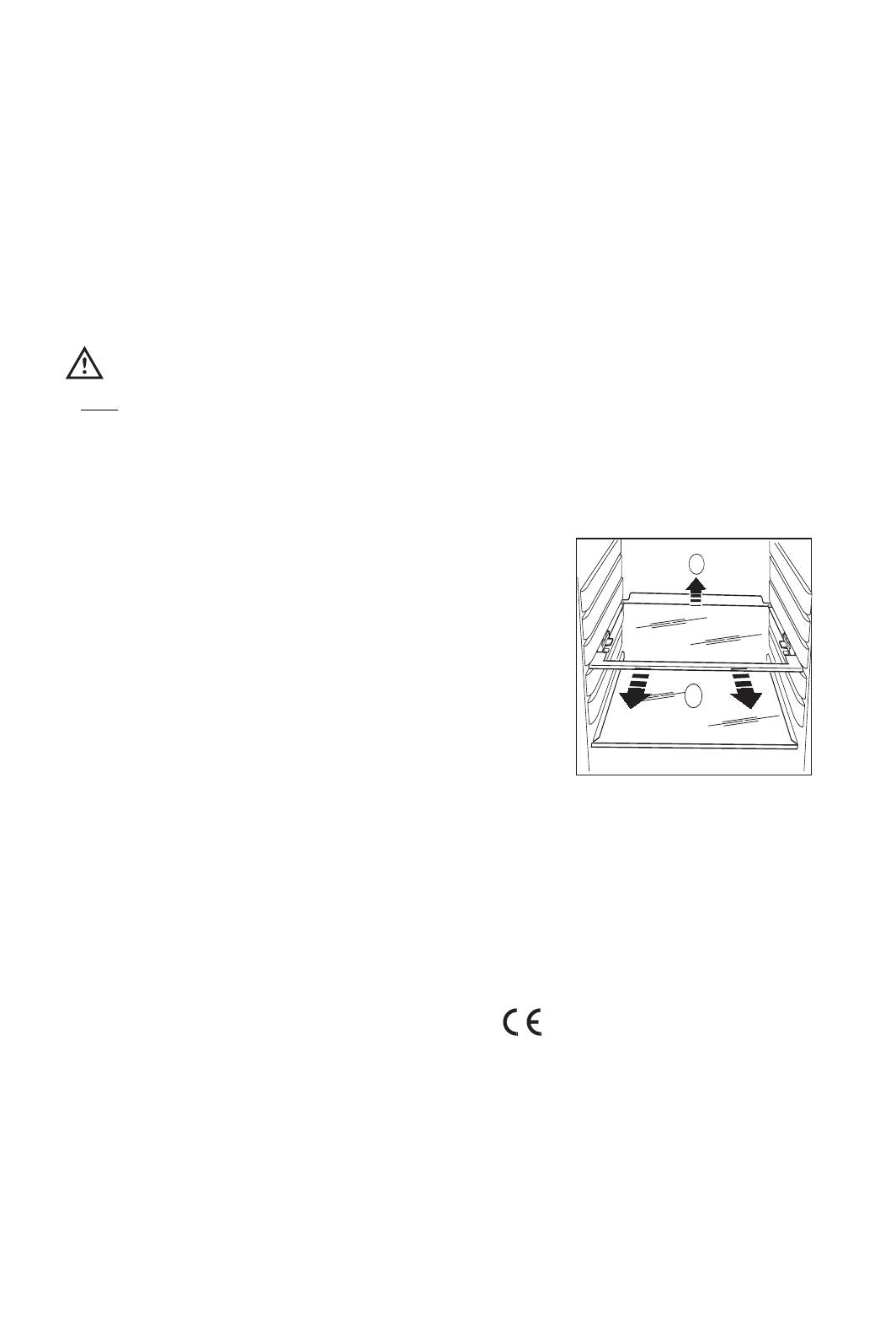
Shelf holders
Your appliance is equipped with shelf retainers that
make it possible to secure the shelves during
transportation.
To remove them proceed as follows:
Raise the shelf from the back, push it in the direction
of the arrow until it is freed and remove the retainers.
The Manufacturer declines all responsibility if
the above safety precautions are not observed.
This appliance complies with the following
E.E.C. Directives:
- 87/308 EEC of 2/6/87 relative to radio interference
suppression.
- 73/23 EEC of 19.2.73 (Low Voltage Directive) and
subsequent modifications;
- 89/336 EEC of 3.5.89 (Electromagnetic Compatibility
Directive) and subsequent modifications.
II
nstructions for totally built-in appliances
Door reversibility
II
nstructions for totally built-in
appliances
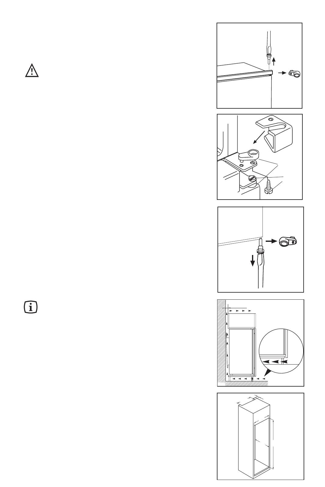
Dimensions of the recess
Height (1) 1780 mm
Depth (2) 550 mm
Width (3) 560 mm
For safety reasons, minimum ventilation must be as
shown in Fig. Attention: keep ventilation
openings clear of obstruction.
Furthermore, it is necessary that the niche is provid
with a conduct of ventilation having the following
dimensions:
depth 50 mm
width 540 mm
47
A
C
B
50 mm
min.
2
200 cm
min.
2
cm
200
D567
The appliance is supplied with the right
or left doors opening. To change the opening
direction of the doors proceed as in the
following instructions before installing it.
1. Unscrew the upper pin and remove the spacer
2. Remove the upper door
3. Unscrew the pins (B) and the spacers (C) and
refit them on the middle hinge of the opposite
side. Snap the hinge cover (A).
4. Refit the upper door, the upper pin and the
spacer on the opposite side
5. Unscrew the lower pin and remove the spacer
and refit them on the opposite side
50
540
3
2
1
PR01
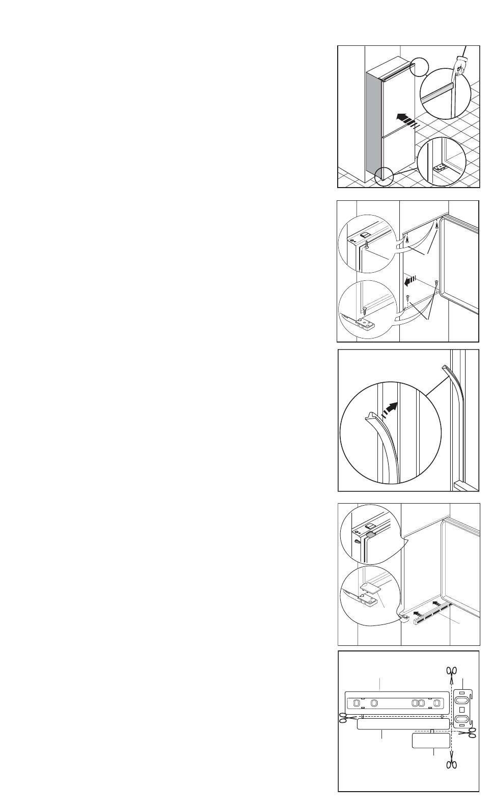
Fit the appliance in the niche by making sure that it
stands against the interior surface of the unit on the
side where the door hinges of the appliances are
fitted. Insert the appliance until the upper strip butts
up against the unit (1) and make sure that the lower
hinge is in line with the surface of the unit (2).
48
1
2
D023
D724
Apply the sealing strip pushing it between the
refrigerator and the adjacent cabinet.
I
P
Fasten the appliance with 4 screws provided in the
kit included with the appliance.
(I = Short) (P = Long)
Apply covers (C-D) on joint cover lugs and into
hinge holes.
Snap vent grille (B) and hinge cover (E) into
position.
Ha
Hb
Hc
Hd
PR266
Separate parts Ha, Hb, Hc, Hd as shown in the
figure.
C
D
E
B
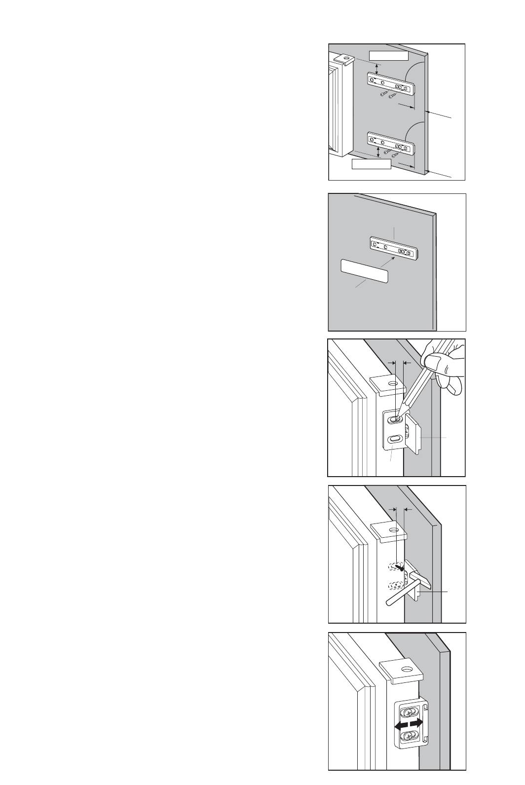
Place guide (Ha) on the inside part of the furniture
door, up and down as shown in the figure and mark
the position of external holes. After having drilled
holes, fix the guide with the screws supplied.
49
ca. 50 mm
90
2
1
m
m
90
ca. 50 mm
2
1
m
m
Fix cover (Hc) on guide (Ha) until it clips into place
Ha
Hc
PR33
8mm
Ha
Hb
PR167
Open the appliance door and the furniture door at
90°. Insert the small square (Hb) into guide (Ha).
Put together the appliance door and the furniture
door and mark the holes as indicated in the figure.
Hb
PR168
Place the small square on the guide again and fix it
with the screws supplied.
Should the lining up of the furniture door be
necessary, use the clearance of slots.
At the end of operations, it is necessary to check if
the door of the furniture closes properly.
8mm
K
Ha
Remove the brackets and mark a distance of 8 mm
from the outer edge of the door where the nail must
be fitted (K).
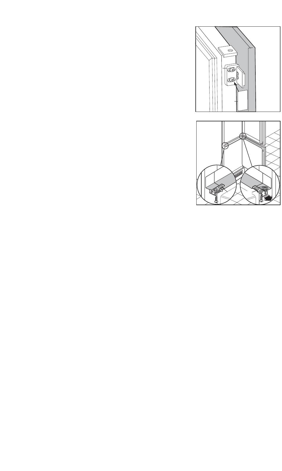
If the appliance is fixed to the side of the kitchen
unit, simply slacken the screws in the fixing brackets
(E), move the brackets as shown in the figure and
re-tighten the screws.
50
E
E
D735
Warning:
After having reversed the opening direction of
the doors check that all the screws are properly
tightened and that the magnetic seal adheres to
the cabinet. If the ambient temperature is cold
(i.e. in Winter), the gasket may not fit perfectly to
the cabinet. In that case, wait for the natural
fitting of the gasket or accelerate this process by
heating up the part involved with a normal
hairdrier.
Hb
Hd
PR167/1
Fix cover (Hd) on guide (Hb) until it clips into place.
Оглавление
- ZZAALLEECCEENNIIAA WWSSTT¢¢PPNNEE
- Głośne działanie
- DDÒÒLLEEÎÎIITTÁÁ UUPPOOZZOORRNNùùNNÍÍ
- HHlluuããnnoosstt
- WARNINGS
- CONTENTS
- USE
- HINTS
- MAINTENANCE
- Noise level
- CUSTOMER SERVICE AND SPARE PARTS
- INSTALLATION
- AVVERTENZE E CONSIGLI IMPORTANTI
- INDICE
- CONSIGLI
- MANUTENZIONE
- Rumorosità
- SE QUALCOSA NON VA
- INSTALLAZIONE
- CENTRI ASSISTENZA
- ПРЕДУПРЕЖДЕНИЯ
- ОГЛАВЛЕНИЕ
- ЭКСПЛУАТАЦИЯ
- РЕКОМЕНДАЦИИ
- УХОД
- Уровень шума
- СЛУЖБА ПОДДЕРЖКИ КЛИЕНТОВ И ЗАПАСНЫЕ ЧАСТИ
- УСТАНОВКА


