Electrolux EGG6242NOX: 8. INSTALLATION
8. INSTALLATION: Electrolux EGG6242NOX
ENGLISH 11
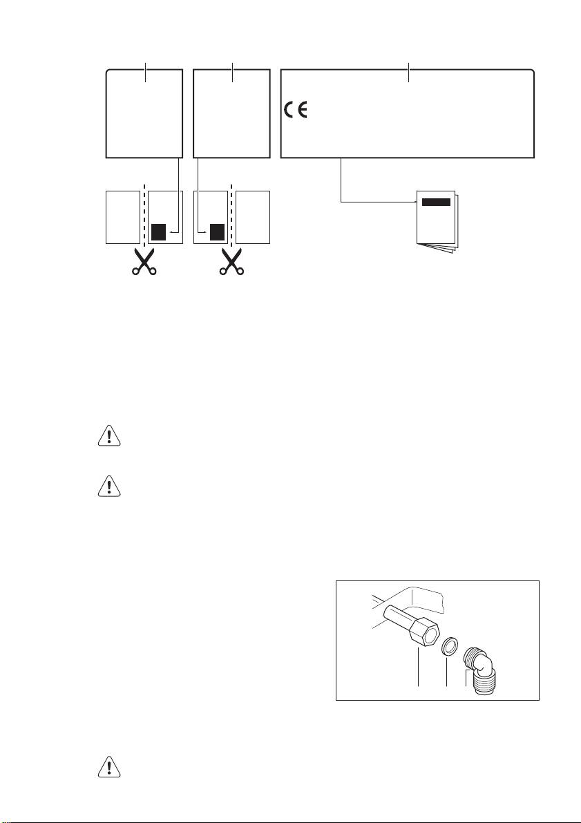
A B C
MOD.
MOD.
MOD.
TYPE
PROD.NO.
230V-50Hz
PROD.NO.
PROD.NO.
SER.NO.
IP20
0049
SER.NO
SER.NO
03 IT
DATA
DATA
MADE IN ITALY
MODELMODEL
A)
Stick it on Guarantee Card and send
C)
Stick it on instruction booklet
this part (if applicable)
B)
Stick it on Guarantee Card and keep
this part (if applicable)
8. INSTALLATION
WARNING!
If the supplied pressure has not the speci-
Refer to "Safety information"
fied value, it is necessary to assemble a
chapter.
proper pressure regulator in compliance
with the standard UNI EN 88. For Liquid
WARNING!
Gas (LPG) the use of pressure regulator is
The following instructions about
allowed only if they are in compliance with
installation, maintenance and ven-
UNI EN 12864. The adjustable connection
tilation must be carried out by
is fixed to the comprehensive ramp by
qualified personnel in compliance
means of a threaded nut G 1/2". Screw
with the regulation in force (UNI-
the parts without force, adjust the con-
CIG 7129 - 7131). Make sure that
nection in the necessary direction and
the kitchen is well ventilated: keep
tighten everything.
natural ventilation holes open (at
least 100 cm²) or install a me-
chanical extractor hood.
8.1 Gas Connection
Choose fixed connections or use a flexible
pipe in stainless steel in compliance with
the regulation in force. If you use flexible
ABC
metallic pipes, be careful they do not
come in touch with mobile parts or they
A)
End of shaft with nut
are not squeezed. Also be careful when
B)
Washer
the hob is put together with an oven.
C)
Elbow
Make sure that the gas supply
pressure of the appliance obeys
the recommended values.
12
www.electrolux.com
Rigid connection:
A
Carry out connection by using metal rigid
pipes (copper with mechanical end) (UNI-
CIG 7129).
Flexible connection:
Use a flexible pipe in stainless steel (UNI-
CIG 9891) with a maximum length 2 m.
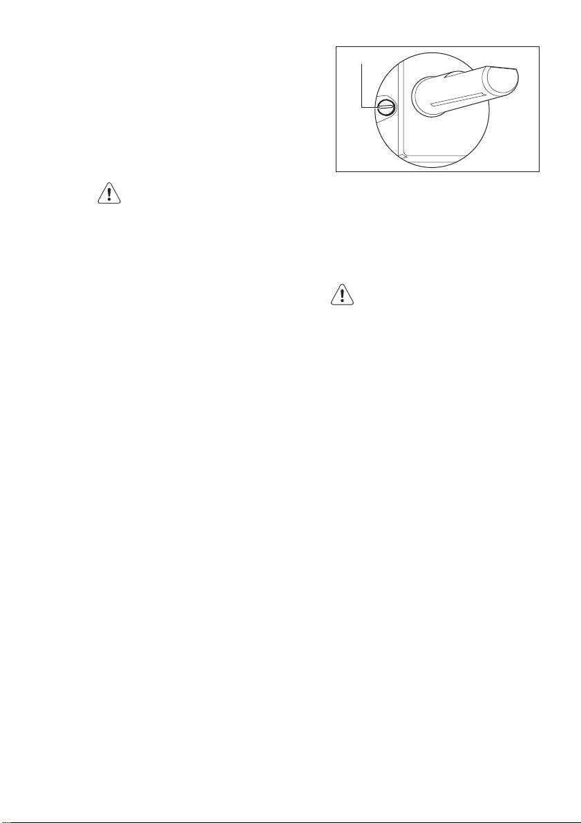
A)
The by-pass screw
When installation is complete,
make sure that the seal of each
• If you change from natural gas G20 20
pipe fitting is correct. Use a soapy
mbar to liquid gas, fully tighten the ad-
solution, not a flame!
justment screw in.
• If you change from liquid gas to natural
gas G20 20 mbar, undo the by-pass
8.2 Injectors replacement
screw approximately 1/4 of a turn.
1.
Remove the pan supports.
WARNING!
2.
Remove the caps and crowns of the
Make sure the flame does not go
burner.
out when you quickly turn the
3.
With a socket spanner 7 remove the
knob from the maximum position
injectors and replace them with the
to the minimum position.
ones which are necessary for the type
of gas you use (see table in "Techni-
8.4 Electrical connection
cal Information" chapter).
4.
Assemble the parts, follow the same
• Ground the appliance according to
procedure backwards.
safety precautions.
5.
Replace the rating plate (it is near the
• Make sure that the rated voltage and
gas supply pipe) with the one for the
type of power on the rating plate agree
new type of gas supply. You can find
with the voltage and the power of the
this plate in the package supplied
local power supply.
with the appliance.
• This appliance is supplied with a mains
If the supply gas pressure is changeable
cable. It has to be supply with a correct
or different from the necessary pressure,
plug, able to support the load marked
you must fit an applicable pressure ad-
on the rating plate. The plug has to be
juster on the gas supply pipe.
fitted in a correct socket.
• Any electrical component must be in-
8.3 Adjustment of minimum level
stalled or replaced by the Service Force
Centre technician or qualified service
To adjust the minimum level of the burn-
personnel.
ers:
• Always use a correctly installed shock-
1.
Light the burner.
proof socket.
2.
Turn the knob on the minimum posi-
• Make sure that there is an access to
tion.
the mains plug after installation.
3.
Remove the knob.
• Do not pull the mains cable to discon-
4.
With a thin screwdriver, adjust the by-
nect the appliance. Always pull the
pass screw position.
mains plug.
• The appliance must not be connected
with an extension cable, an adapter or
a multiple connection (risk of fire).
Check that the ground connection is in
conformity with the standard and regu-
lations force.
ENGLISH 13
• The power cable must be placed in
such a way that it does not touch any
hot part.
• Connect the appliance to the mains
with a device that lets to disconnect the
A
appliance from the mains at all poles
with a contact opening width of mini-
mum 3 mm, eg. automatic line protect-
10 mm
11 mm
ing cut-out, earth leakage trips or fuse.
3 mm
No part of the power cable must heat to a
11 mm
temperature of more than 90° C.
Use clamps installed on the side of the
cabinet to prevent contact with the equip-
ment below the cooktop. See an example
A
of an optimal path in Figure.
A
B
A)
supplied seal
B)
supplied brackets
A)
Rigid copper pipe or flexible pipe in
stainless steel
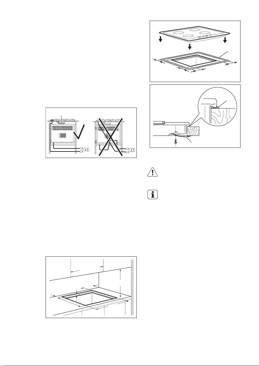
CAUTION!
Install the appliance only on a
worktop with flat surface.
8.5 Replacement of the
connection cable
If you install the hob under a
hood, please see the installation
To replace the connection cable use only
instructions of the hood for the
H05V2V2-F T90 or equivalent type. Make
minimum distance between the
sure that the cable section is applicable to
appliances.
the voltage and the working temperature.
The yellow/green earth wire must be ap-
proximately 2 cm longer than the brown
8.7 Possibilities for insertion
(or black) phase wire.
Kitchen unit with door
8.6 Building In
The panel installed below the hob must
be easy to remove and let an easy access
in case a technical assistance intervention
min. 600 mm
is necessary.
min. 150 mm
min. 650 mm
min. 55 mm
30 mm
480 mm
560 mm
Оглавление
- CONTENTS
- 1. SAFETY INFORMATION
- 2. SAFETY INSTRUCTIONS
- 3. PRODUCT DESCRIPTION
- 5. HELPFUL HINTS AND TIPS
- 6. CARE AND CLEANING
- 7. TROUBLESHOOTING
- 8. INSTALLATION
- 9. TECHNICAL INFORMATION
- 10. ENVIRONMENT CONCERNS
- INHALT
- 1. SICHERHEITSINFORMATIONEN
- 2. SICHERHEITSHINWEISE
- 3. GERÄTEBESCHREIBUNG
- 4. TÄGLICHER GEBRAUCH
- 5. PRAKTISCHE TIPPS UND HINWEISE
- 7. FEHLERSUCHE
- 8. MONTAGE
- 9. TECHNISCHE DATEN
- 10. UMWELTTIPPS
- СОДЕРЖАНИЕ
- 1. СВЕДЕНИЯ ПО ТЕХНИКЕ БЕЗОПАСНОСТИ
- 2. УКАЗАНИЯ ПО БЕЗОПАСНОСТИ
- 3. ОПИСАНИЕ ИЗДЕЛИЯ
- 4. ЕЖЕДНЕВНОЕ ИСПОЛЬЗОВАНИЕ
- 5. ПОЛЕЗНЫЕ СОВЕТЫ
- 7. ПОИСК И УСТРАНЕНИЕ НЕИСПРАВНОСТЕЙ
- 8. УСТАНОВКА
- 9. ТЕХНИЧЕСКИЕ ДАННЫЕ
- 10. ОХРАНА ОКРУЖАЮЩЕЙ СРЕДЫ
