Yamaha A-S700: CONNECTIONS
CONNECTIONS: Yamaha A-S700
PREPARATION
CONNECTIONS
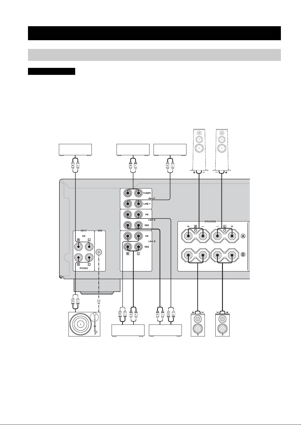
Connecting speakers and other components
CAUTION
• Do not connect this unit or other components to the main power until all connections between components are
complete.
• All connections must be correct: L (left) to L, R (right) to R, “+” to “+” and “–” to “–”. If the connections are faulty,
no sound will be heard from the speakers, and if the polarity of the speaker connections is incorrect, the sound will be
unnatural and lack bass. Also, refer to the owner’s manual for each of your components.
• Use RCA stereo cable for audio units except speakers.
Speakers A
CD player DVD player, etc.
Tuner
Audio out
Audio out
Audio out
Audio out
GND
Audio
Audio
out
Audio in
out
Turntable
Tape deck, etc.
CD recorder,
Speakers B
etc.
y
• The PHONO jacks are designed to connect a turntable with an MM cartridge.
• Connect your turntable to the GND terminal to reduce noise in the signal. However, you may hear less noise without the connection to
the GND terminal for some turntable(s).
6 En
CONNECTIONS
CAUTION
• The IMPEDANCE SELECTOR must be set to the appropriate position before connecting one or two speaker sets.
See page 5 for details.
• Do not let the bare speaker wires touch each other or do not let them touch any metal part of this unit. This could
damage this unit and/or the speakers.
• Do not connect this unit or other components to the main power until all connections between components are
complete.
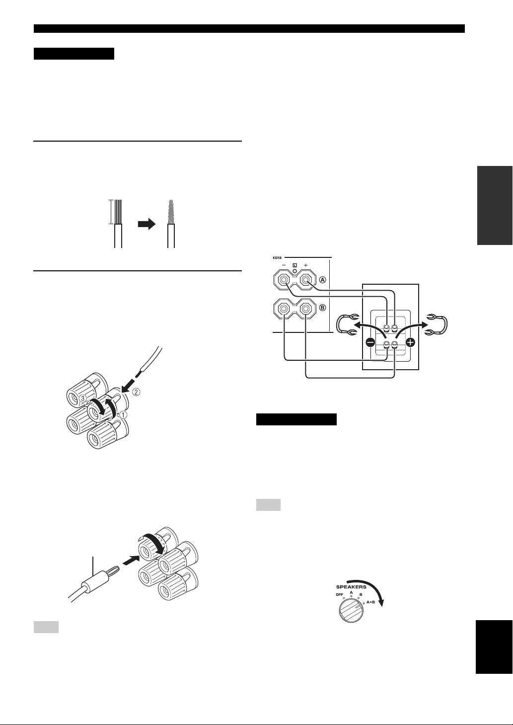
■ Bi-wire connection
1 Remove approximately 10 mm (3/8 in) of
The bi-wire connection separates the woofer from the
insulation from the end of each speaker
combined midrange and tweeter section. A bi-wire
PREPARATION
cable and twist the exposed wires of the
compatible speaker has four binding post terminals. These
two sets of terminals allow the speaker to be split into two
cable together to prevent short circuits.
independent sections. With these connections, the mid and
high frequency drivers are connected to one set of
10 mm (3/8 in)
terminals and the low frequency driver to another set of
terminals.
This unit
Speaker
2 Connect the speaker cable.
1 Unscrew the knob.
2 Insert one bare wire into the hole in the side
of each terminal.
3 Tighten the knob to secure the wire.
Red: positive (+)
Connect the other speaker to the other set of terminals in
Black: negative (–)
the same way.
CAUTION
When making bi-wire connections, set the IMPEDANCE
SELECTOR switch to HIGH or LOW depending on the
impedance of your speakers:
■ Connecting via banana plug
6 Ω or higher: HIGH
(Except for Asia, Korea, U.K. and Europe
4 Ω or higher: LOW
See page 5 for IMPEDANCE SELECTOR switch.
models)
First, tighten the knob and then insert the banana plug into
Note
the end of the corresponding terminal.
When making bi-wire connections, remove the shorting bridges
or cables on the speaker.
y
Banana plug
To use the bi-wire connections, switch the SPEAKERS selector
to the A+B position.
Note
English
One or two speaker sets can be connected to this unit.
7 En
CONNECTIONS
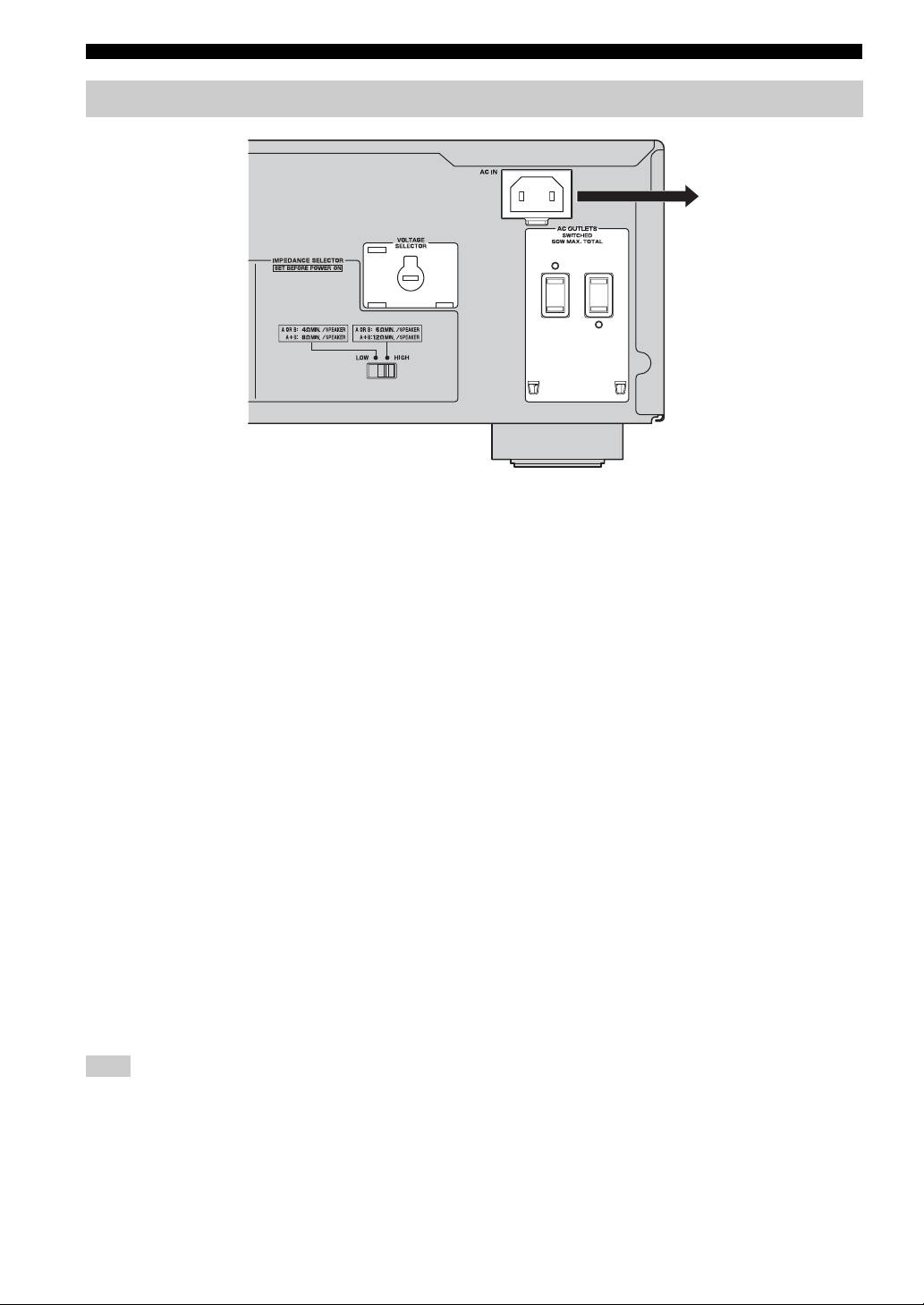
Connecting the supplied power cable
To the wall outlet with the
supplied power cable
(Asia and General models)
■ VOLTAGE SELECTOR
(Asia and General models only)
The VOLTAGE SELECTOR on the rear panel of this unit
must be set for your local main voltage BEFORE plugging
the supplied power cable into the wall outlet.
Improper setting of the VOLTAGE SELECTOR may
cause damage to this unit and create a potential fire
hazard.
Rotate the VOLTAGE SELECTOR clockwise or
counterclockwise to the correct position using a straight
slot screwdriver.
Voltages are as follows:
Asia model.......................... AC 220/230–240 V, 50/60 Hz
General model ......AC 110/120/220/230–240 V, 50/60 Hz
■ AC OUTLET(S) (SWITCHED)
U.K. and Australia models ..................................... 1 outlet
Korea model .............................................................. None
Other models ........................................................ 2 outlets
Use these outlets to connect the power cables from your
other components to this unit. The power to the AC
OUTLET(S) is controlled by POWER on the front panel
of this unit (or on the remote control). The outlet(s) supply
power to any connected component whenever the power
of this unit is turned on. For information on the maximum
power (total power consumption of components), see
“SPECIFICATIONS” on page 15.
Note
Do not connect components with a built-in amplifier, such as a
subwoofer, etc.
■ Connecting the supplied power cable
Plug the supplied power cable into the AC IN on the rear
panel of this unit and then, plug the power cable into the
wall outlet after all other connections are complete.
8 En
Оглавление
- CAUTION: READ THIS BEFORE OPERATING YOUR UNIT.
- CONTENTS
- CONTROLS AND FUNCTIONS
- CONNECTIONS
- PLAYING AND RECORDING
- TROUBLESHOOTING
- SPECIFICATIONS
- ATTENTION : VEUILLEZ LIRE CE QUI SUIT AVANT D’UTILISER L’APPAREIL.
- TABLE DES MATIÈRES
- COMMANDES ET FONCTIONS
- RACCORDEMENTS
- LECTURE ET ENREGISTREMENT
- GUIDE DE DÉPANNAGE
- CARACTÉRISTIQUES TECHNIQUES
- VORSICHT: VOR DER BEDIENUNG DIESES GERÄTES DURCHLESEN.
- INHALT
- BEDIENELEMENTE UND IHRE FUNKTIONEN
- ANSCHLÜSSE
- WIEDERGABE UND AUFNAHME
- STÖRUNGSBEHEBUNG
- TECHNISCHE DATEN
- OBSERVERA: LÄS DETTA INNAN ENHETEN TAS I BRUK.
- INNEHÅLL
- REGLAGE OCH FUNKTIONER
- ANSLUTNINGAR
- SPELA UPP OCH SPELA IN
- FELSÖKNING
- TEKNISKA DATA
- ATTENZIONE: PRIMA DI USARE QUEST’UNITÀ.
- INDICE
- COMANDI E FUNZIONI
- COLLEGAMENTI
- RIPRODUZIONE E REGISTRAZIONE
- RISOLUZIONE DEI PROBLEMI
- DATI TECNICI
- PRECAUCIÓN: LEA LAS INDICACIONES SIGUIENTES ANTES DE UTILIZAR ESTE APARATO.
- ÍNDICE
- CONTROLES Y FUNCIONES
- CONEXIONES
- REPRODUCCIÓN Y GRABACIÓN
- SOLUCIÓN DE PROBLEMAS
- ESPECIFICACIONES
- LET OP: LEES HET VOLGENDE VOOR U DIT TOESTEL IN GEBRUIK NEEMT.
- INHOUD
- REGELAARS EN HUN FUNCTIES
- AANSLUITINGEN
- AFSPELEN EN OPNEMEN
- PROBLEMEN OPLOSSEN
- TECHNISCHE GEGEVENS
- ПРЕДУПРЕЖДЕНИЕ: ВНИМАТЕЛЬНО ИЗУЧИТЕ ЭТО ПЕРЕД ИСПОЛЬЗОВАНИЕМ АППАРАТА.
- СОДЕРЖАНИЕ
- ОРГАНЫ УПРАВЛЕНИЯ И ФУНКЦИИ
- СОЕДИНЕНИЯ
- ВОСПРОИЗВЕДЕНИЕ И ЗАПИСЬ
- ВОЗМОЖНЫЕ НЕИСПРАВНОСТИ И СПОСОБЫ ИХ УСТРАНЕНИЯ
- ТЕХНИЧЕСКИЕ ХАРАКТЕРИСТИКИ
