Yamaha A-S700: instruction
Class: Household, kitchen appliances, electronics and equipment
Type:
Manual for Yamaha A-S700
Table of contents
- CAUTION: READ THIS BEFORE OPERATING YOUR UNIT.
- CONTENTS FEATURES SUPPLIED ACCESSORIES
- CONTROLS AND FUNCTIONS Front panel
- Remote control
- Installing batteries in the remote Using the remote control control
- Rear panel
- Connecting speakers and other components CAUTION
- ■ Bi-wire connection CAUTION ■ Connecting via banana plug
- Connecting the supplied power cable
- Playing a source
- ■ Using the PURE DIRECT switch ■ Adjusting the BASS and TREBLE controls Adjusting the tonal quality ■ Using the CD DIRECT AMP switch
- ■ Adjusting the LOUDNESS control Recording a source
- TROUBLESHOOTING ■ General Problems Possible Causes Solutions
- Problems Possible Causes Solutions
- ■ Remote control Problems Possible Causes Solutions
- SPECIFICATIONS

G
Integrated Amplifier
Amplificateur Intégré
OWNER’S MANUAL
MODE D’EMPLOI
BEDIENUNGSANLEITUNG
BRUKSANVISNING
MANUALE DI ISTRUZIONI
MANUAL DE INSTRUCCIONES
GEBRNUIKSAANWIJZIG
CAUTION: READ THIS BEFORE OPERATING YOUR UNIT.
1 To assure the finest performance, please read this manual
19 VOLTAGE SELECTOR (Asia and General models only)
carefully. Keep it in a safe place for future reference.
The VOLTAGE SELECTOR on the rear panel of this unit
2 Install this sound system in a well ventilated, cool, dry, clean
must be set for your local main voltage BEFORE plugging
into the wall outlet. Voltages are:
place – away from direct sunlight, heat sources, vibration,
Asia model............................. AC 220/230–240 V, 50/60 Hz
dust, moisture, and/or cold. Allow ventilation space of at least
General model ......... AC 110/120/220/230–240 V, 50/60 Hz
30 cm (11-13/16 in) on the top, 20 cm (7-7/8 in) on the left
and right, and 20 cm (7-7/8 in) on the back of this unit.
20 The batteries shall not be exposed to excessive heat such as
sunshine, fire or like.
3 Locate this unit away from other electrical appliances, motors,
21 Excessive sound pressure from earphones and headphones
or transformers to avoid humming sounds.
can cause hearing loss.
4 Do not expose this unit to sudden temperature changes from
cold to hot, and do not locate this unit in an environment with
As long as this unit is connected to the wall outlet, it is
high humidity (i.e. a room with a humidifier) to prevent
not disconnected from the AC power source even if
condensation inside this unit, which may cause an electrical
you turn off this unit by POWER or set it to the
shock, fire, damage to this unit, and/or personal injury.
standby mode by button on the remote control.
5 Avoid installing this unit where foreign objects may fall onto
this unit and/or this unit may be exposed to liquid dripping or
splashing. On the top of this unit, do not place:
WARNING
– Other components, as they may cause damage and/or
TO REDUCE THE RISK OF FIRE OR ELECTRIC
discoloration on the surface of this unit.
SHOCK, DO NOT EXPOSE THIS UNIT TO RAIN
– Burning objects (i.e. candles), as they may cause fire,
OR MOISTURE.
damage to this unit, and/or personal injury.
– Containers with liquid in them, as they may fall and liquid
This unit enters the standby mode when you press
may cause electrical shock to the user and/or damage to
POWER inward to the ON position and then press
this unit.
button on the remote control. In this state, this unit is
6 Do not cover this unit with a newspaper, tablecloth, curtain,
etc. in order not to obstruct heat radiation. If the temperature
designed to consume a very small quantity of power.
inside this unit rises, it may cause fire, damage to this unit,
and/or personal injury.
7 Do not plug in this unit to a wall outlet until all connections
are complete.
8 Do not operate this unit upside-down. It may overheat,
possibly causing damage.
9 Do not use force on switches, knobs and/or cords.
10 When disconnecting the power cable from the wall outlet,
grasp the plug; do not pull the cable.
11 Do not clean this unit with chemical solvents; this might
damage the finish. Use a clean, dry cloth.
12 Only voltage specified on this unit must be used. Using this
unit with a higher voltage than specified is dangerous and may
cause fire, damage to this unit, and/or personal injury.
Yamaha will not be held responsible for any damage resulting
from use of this unit with a voltage other than specified.
13 To prevent damage by lightning, keep the power cable
disconnected from a wall outlet or the unit during a lightning
storm.
14 Do not attempt to modify or fix this unit. Contact qualified
Yamaha service personnel when any service is needed. The
cabinet should never be opened for any reasons.
15 When not planning to use this unit for long periods of time
(i.e. vacation), disconnect the AC power plug from the wall
outlet.
16 Install this unit near the AC outlet and where the AC power
plug can be reached easily.
17 Be sure to read the “TROUBLESHOOTING” section in the
owner’s manual on common operating errors before
concluding that this unit is faulty.
18 Before moving this unit, press POWER to turn off this unit
and then disconnect the AC power plug from the wall outlet.
i En
CONTENTS
INTRODUCTION
OPERATION
FEATURES............................................................. 1
PLAYING AND RECORDING.............................9
SUPPLIED ACCESSORIES ................................. 1
Playing a source......................................................... 9
CONTROLS AND FUNCTIONS ......................... 2
Adjusting the tonal quality ...................................... 10
Front panel................................................................. 2
Recording a source .................................................. 11
Remote control........................................................... 3
Installing batteries in the remote control ................... 4
Using the remote control ........................................... 4
ADDITIONAL INFORMATION
PREPARATIONINTRODUCTION
Rear panel.................................................................. 5
TROUBLESHOOTING .......................................12
SPECIFICATIONS...............................................15
PREPARATION
CONNECTIONS .................................................... 6
Connecting speakers and other components.............. 6
Connecting the supplied power cable........................ 8
OPERATION
■ About this manual
• y indicates a tip for your operation.
• Some operations can be performed by using either the buttons on the main unit or on the remote control. In cases
when the button names differ between the main unit and the remote control, the names of the buttons on the remote
control are given in parentheses.
• This manual is printed prior to production. Design and specifications are subject to change in part as a result of
improvements, etc. In case of differences between the manual and the product, the product has priority.
INTRODUCTION
INFORMATION
ADDITIONAL
FEATURES
◆ Highly dynamic power, low impedance drive capability
◆ Minimum RMS output power
◆ Continuously variable loudness control
90 W + 90 W (8 Ω), 0.019% THD, 20 Hz to 20 kHz
◆ CD DIRECT AMP switch used to obtain the highest
◆ REC OUT selector independent of input source selection
sound quality of compact discs
◆ Remote control capability
◆ PURE DIRECT switch used to reproduce the purest
source sound
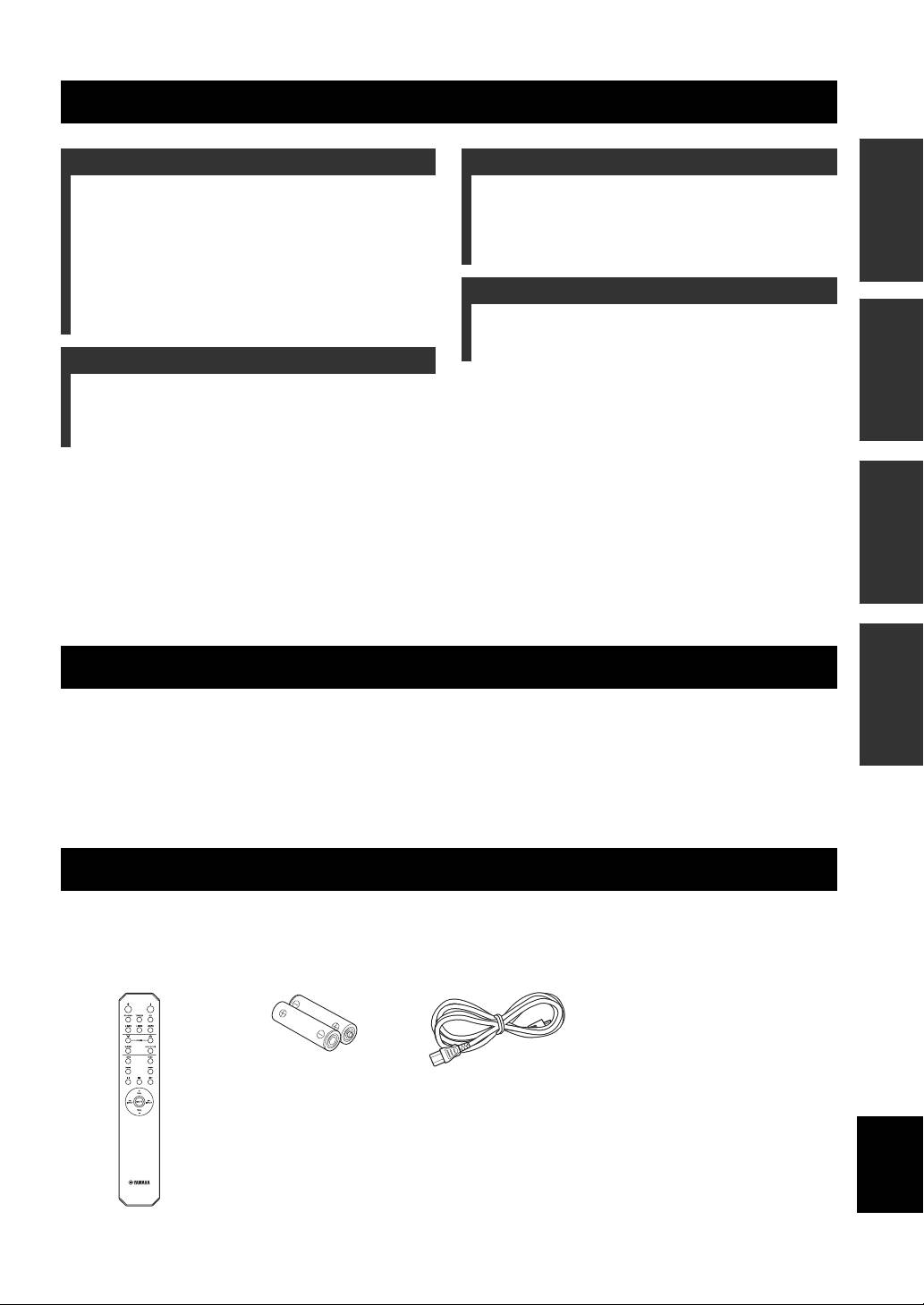
SUPPLIED ACCESSORIES
Please check that you received all of the following parts:
Remote control Batteries (× 2)
Power cable
(AA, R6, UM-3)
English
1 En
CONTROLS AND FUNCTIONS
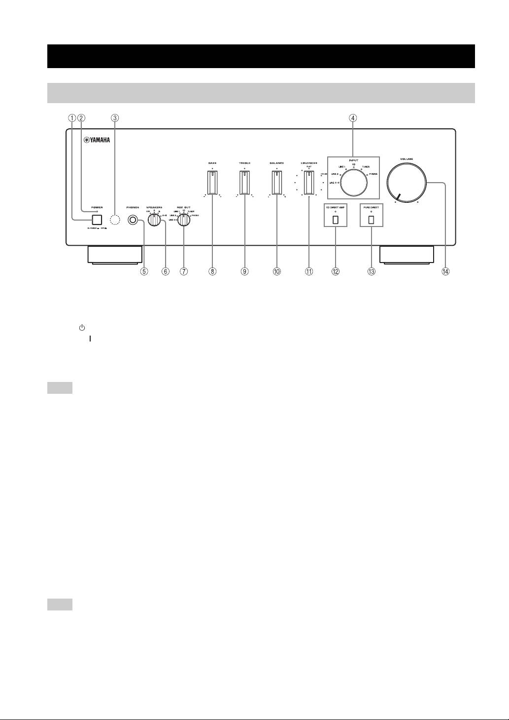
Front panel
1 POWER
5 PHONES jack
Press inward to the ON position to turn on the power of
Connect headphones for private listening.
this unit. You can set this unit to standby mode by
Rotate the SPEAKERS selector on the front panel to the
pressing button on the remote control or turn on the unit
OFF position to turn off the sound from the speakers.
by pressing button on the remote control when this unit is
6 SPEAKERS selector
turned on.
Turn on or off the speaker set connected to the
Press again to release it outward to the OFF position to
SPEAKERS A and/or B terminals on the rear panel each
turn off this unit.
time the corresponding SPEAKERS selector is set to A, B
Note
or A+B.
Even when this unit is turned off, this unit consumes a small
7 REC OUT selector
amount of power to preserve the memory.
Select a source for recording independently of the INPUT
2 POWER on indicator
selector setting, allowing you to record the selected source
while listening to another source.
Lights up as follows:
See page 11 for details.
ON: Bright
Standby mode: Dark
8 BASS
OFF: Off
Increase or decrease the low frequency response.
3 Remote control sensor
See page 10 for details.
Receives signals from the remote control.
9 TREBLE
4 INPUT selector and indicators
Increase or decrease the high frequency response.
See page 10 for details.
Select the input source you want to listen to.
The input source indicators light up when the
0 BALANCE
corresponding input sources are selected.
Adjust the sound output balance of the left and right
y
speakers. See page 10 for details.
The input source names correspond to the names of the
A LOUDNESS
connection jacks on the rear panel.
Retain a full tonal range at any volume level.
Note
See page 11 for details.
The input setting is retained for about 1 week after the power
B CD DIRECT AMP and indicator
cable is unplugged.
Reproduces CD sound in the highest signal quality
regardless of the INPUT selector setting.
The indicator above it lights up when this function is
turned on. See page 10 for details.
2 En
CONTROLS AND FUNCTIONS
C PURE DIRECT and indicator
D VOLUME
Reproduces any input source in the purest sound possible.
Control the sound output level.
The indicator above it lights up when this function is
This does not affect the REC level for recording.
turned on. See page 10 for details.
INTRODUCTION
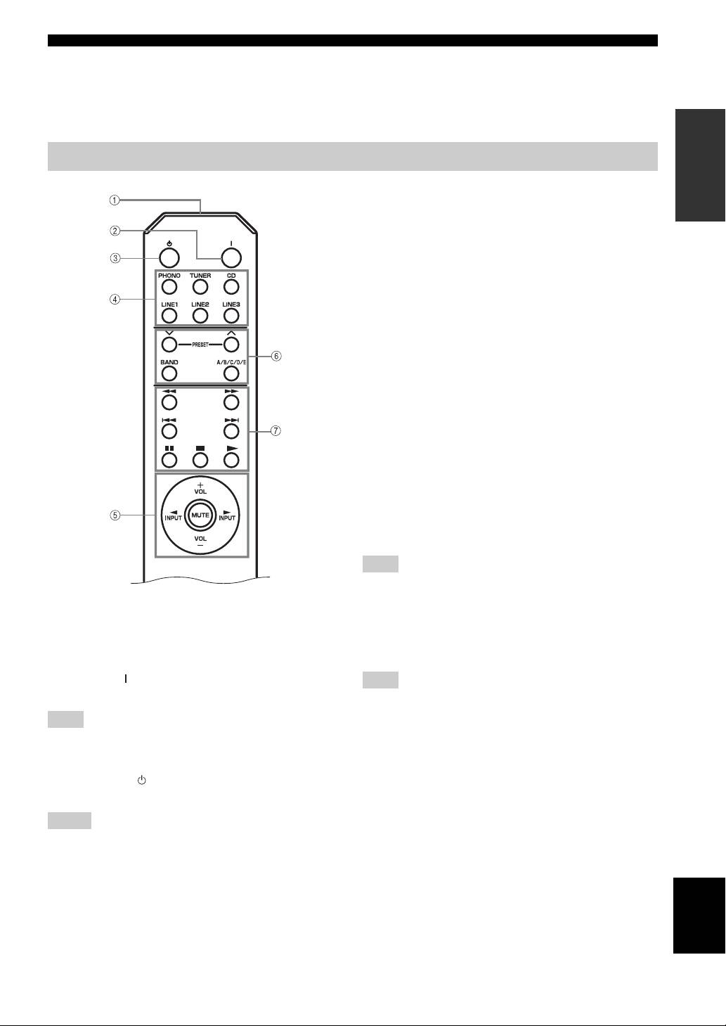
Remote control
4 Input selector buttons
Select the input source you want to listen to.
5 Amplifier control buttons
INPUT l / h
Select the input source you want to listen to.
VOL +/–
Control the sound output level.
This does not affect the REC level for recording.
MUTE
Mute the sound output. Press MUTE again to resume the
audio output. Selected Input indicator blinks when the
sound is muted.
■ Controlling other components
The functions of the buttons to control other Yamaha
components are the same as those of the corresponding
buttons on those components. Refer to the components’
instruction manuals for details.
6 Yamaha tuner control buttons
Control various functions of Yamaha tuner. Refer to the
owner’s manual of your tuner for details.
Note
Not all Yamaha tuners or functions can be controlled by this
remote control.
■ Controlling this unit
7 Yamaha CD player control buttons
1 Infrared signal transmitter
Control various functions of Yamaha CD player. Refer to
Sends signals to the main unit.
the owner’s manual of your CD player for details.
2 POWER ( )
Note
Turn on the unit.
Not all Yamaha CD players or functions can be controlled by this
remote control.
Note
This button is operational only when POWER on the front panel
is pressed inward to the ON position.
3 STANDBY ( )
Set this unit to the standby mode.
Notes
• This button is operational only when POWER on the front
panel is pressed inward to the ON position.
• In the standby mode, this unit consumes a small amount of
power in order to receive infrared-signals from the remote
English
control.
3 En
CONTROLS AND FUNCTIONS
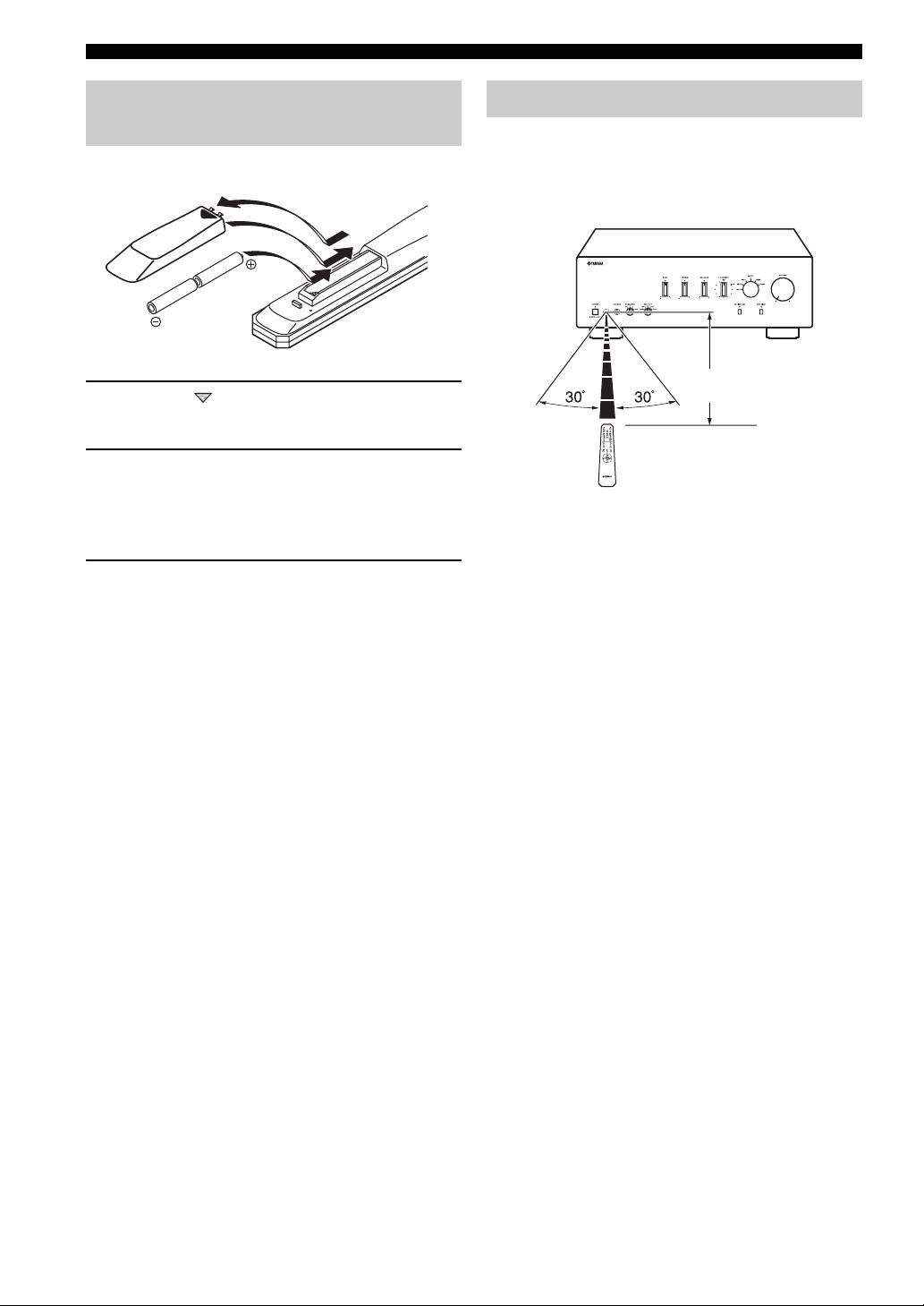
Installing batteries in the remote
Using the remote control
control
The remote control transmits a directional infrared beam.
Be sure to aim the remote control directly at the remote
control sensor on the front panel of this unit during
1
operation.
3
2
Within 6m
1 Press the part and slide the battery
(20 ft)
compartment cover off.
2 Insert two supplied batteries
(AA, R6, UM-3) according to the polarity
markings (+ and –) on the inside of the
battery compartment.
■ Handling the remote control
• The area between the remote control and this unit must
be clear of large obstacles.
3 Slide the cover back until it snaps into place.
• Do not spill water or other liquids on the remote
control.
■ Notes on batteries
• Do not drop the remote control.
• Change both batteries when the operation range of the
• Do not leave or store the remote control in the
remote control decreases.
following types of conditions:
• Use AA, R6, UM-3 batteries.
– high humidity, such as near a bath
• Make sure that the polarities are correct. See the
– high temperature, such as near a heater or a stove
illustration inside the battery compartment.
– extremely low temperatures
• Remove the batteries if the remote control is not to be
– dusty places
used for an extended period of time.
• Do not expose the remote control sensor to strong
• Do not use old batteries together with new ones.
lighting, in particular, an inverter type fluorescent
• Do not use different types of batteries (such as alkaline
lamp; otherwise, the remote control may not work
and manganese batteries) together. Read the packaging
properly. If necessary, position the unit away from
carefully as these different types of batteries may have
direct lighting.
the same shape and color.
• If the batteries have leaked, dispose of them
immediately. Avoid touching the leaked material or
letting it come into contact with clothing, etc. Clean the
battery compartment thoroughly before installing new
batteries.
• Do not throw away batteries with general house waste;
dispose of them correctly in accordance with your local
regulations.
4 En
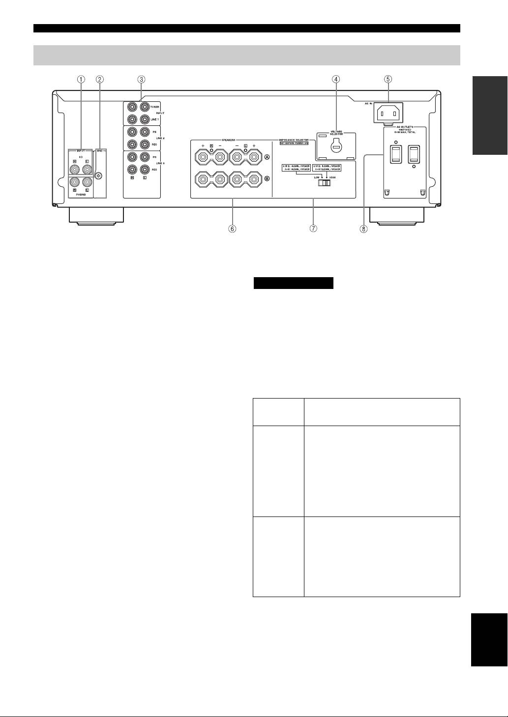
CONTROLS AND FUNCTIONS
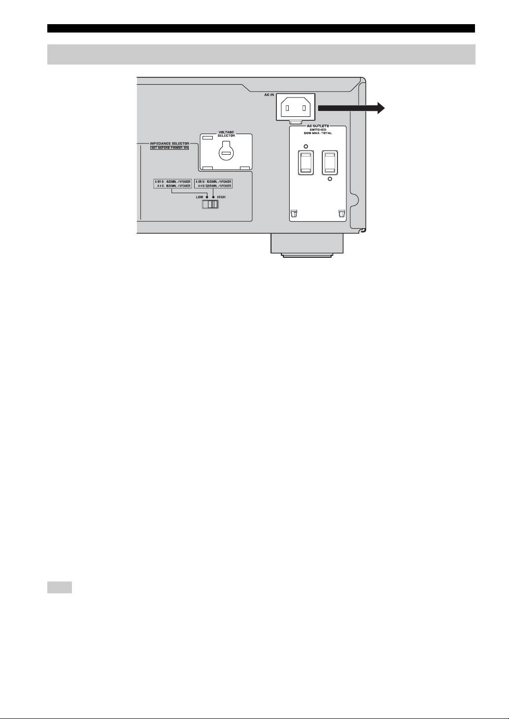
Rear panel
INTRODUCTION
(Asia and General models)
1 CD input jacks
■ IMPEDANCE SELECTOR switch
Connect a CD player.
CAUTION
See page 6 for connection information.
Do not change the IMPEDANCE SELECTOR switch
2 PHONO jacks and GND terminal
while the power of this unit is turned on, as doing so may
The PHONO jacks are designed to connect a turntable
damage the unit.
with an MM cartridge.
If the unit fails to turn on, the IMPEDANCE SELECTOR
See page 6 for connection information.
switch may not be fully slid to either position. If this is the
3 Audio input/output jacks
case, slide the switch all the way to either position when
Connect external components, such as a tuner, etc.
this unit’s power supply is completely cut off.
See page 6 for connection information.
Select the switch position (LOW or HIGH) according to
the impedance of the speakers in your system.
4 VOLTAGE SELECTOR
(Asia and General models only)
Switch
Impedance level
The VOLTAGE SELECTOR must be set to your local
position
main voltage before plugging the supplied power cable
• If you use one set (A or B), the impedance of
into the wall outlet.
the speaker must be 6
Ω or higher.
See page 8 for details.
• If you use two sets (A and B) simultaneously,
the impedance of each speaker must be 12
Ω
5 AC IN
HIGH
or higher. (Except for U.S.A and Canada
Use to plug in the supplied power cable.
models)
See page 8 for connection information.
• If you make bi-wire connections, the
impedance of the speaker must be 6
Ω or
6 SPEAKERS terminals
higher. See page 7 for details.
Connect one or two speaker sets.
• If you use one set (A or B), the impedance of
See page 6 for connection information.
the speaker must be 4
Ω or higher.
• If you use two sets (A and B) simultaneously,
7 IMPEDANCE SELECTOR switch
the impedance of each speaker must be 8
Ω or
See IMPEDANCE SELECTOR switch on this page.
LOW
higher.
• If you make bi-wire connections, the
8 AC OUTLET(S)
impedance of the speaker must be 4
Ω or
Use to supply power to your other audio/video
higher. See page 7 for details.
components.
See page 8 for details.
English
5 En
PREPARATION
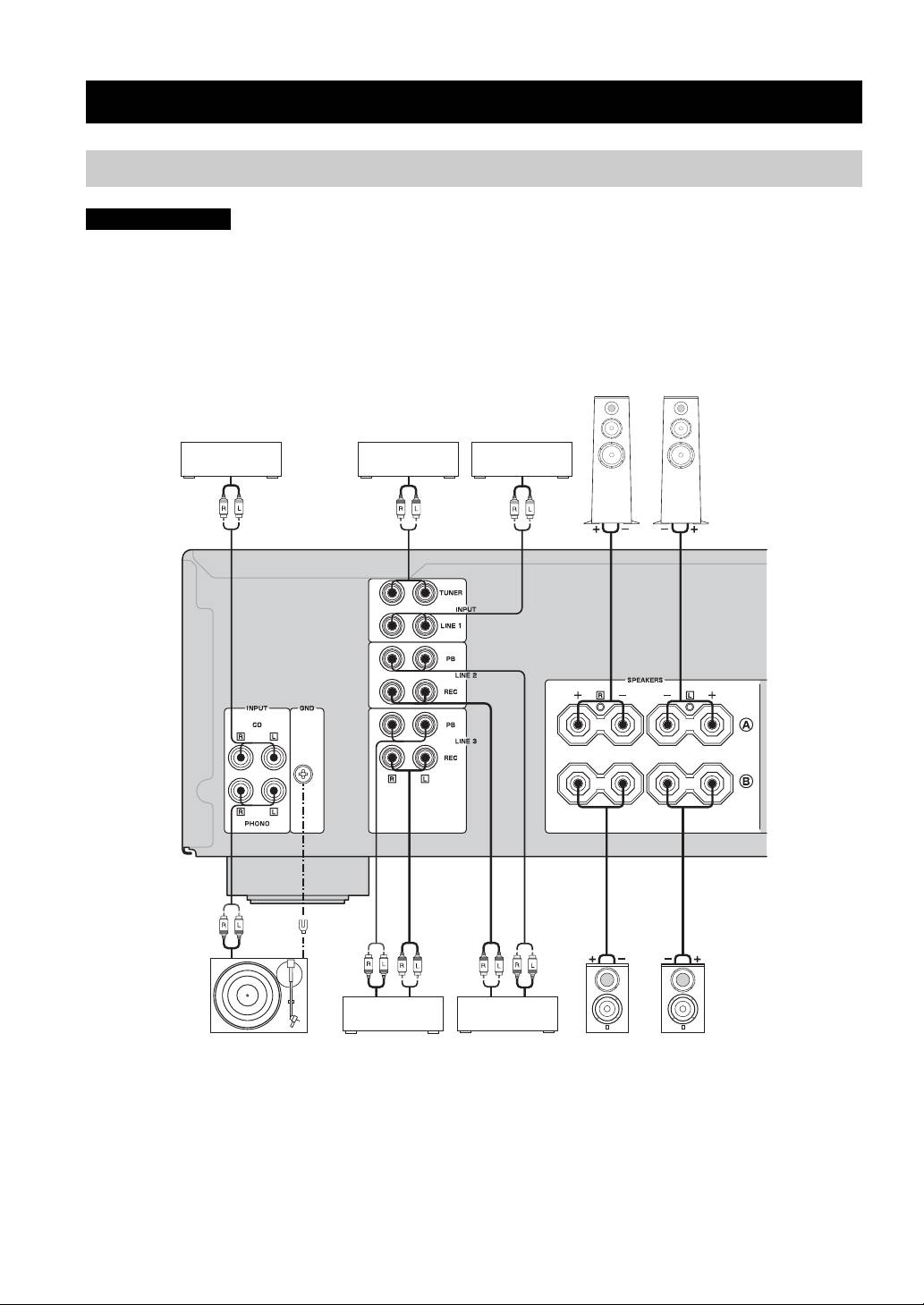
CONNECTIONS
Connecting speakers and other components
CAUTION
• Do not connect this unit or other components to the main power until all connections between components are
complete.
• All connections must be correct: L (left) to L, R (right) to R, “+” to “+” and “–” to “–”. If the connections are faulty,
no sound will be heard from the speakers, and if the polarity of the speaker connections is incorrect, the sound will be
unnatural and lack bass. Also, refer to the owner’s manual for each of your components.
• Use RCA stereo cable for audio units except speakers.
Speakers A
CD player DVD player, etc.
Tuner
Audio out
Audio out
Audio out
Audio out
GND
Audio
Audio
out
Audio in
out
Turntable
Tape deck, etc.
CD recorder,
Speakers B
etc.
y
• The PHONO jacks are designed to connect a turntable with an MM cartridge.
• Connect your turntable to the GND terminal to reduce noise in the signal. However, you may hear less noise without the connection to
the GND terminal for some turntable(s).
6 En
CONNECTIONS
CAUTION
• The IMPEDANCE SELECTOR must be set to the appropriate position before connecting one or two speaker sets.
See page 5 for details.
• Do not let the bare speaker wires touch each other or do not let them touch any metal part of this unit. This could
damage this unit and/or the speakers.
• Do not connect this unit or other components to the main power until all connections between components are
complete.
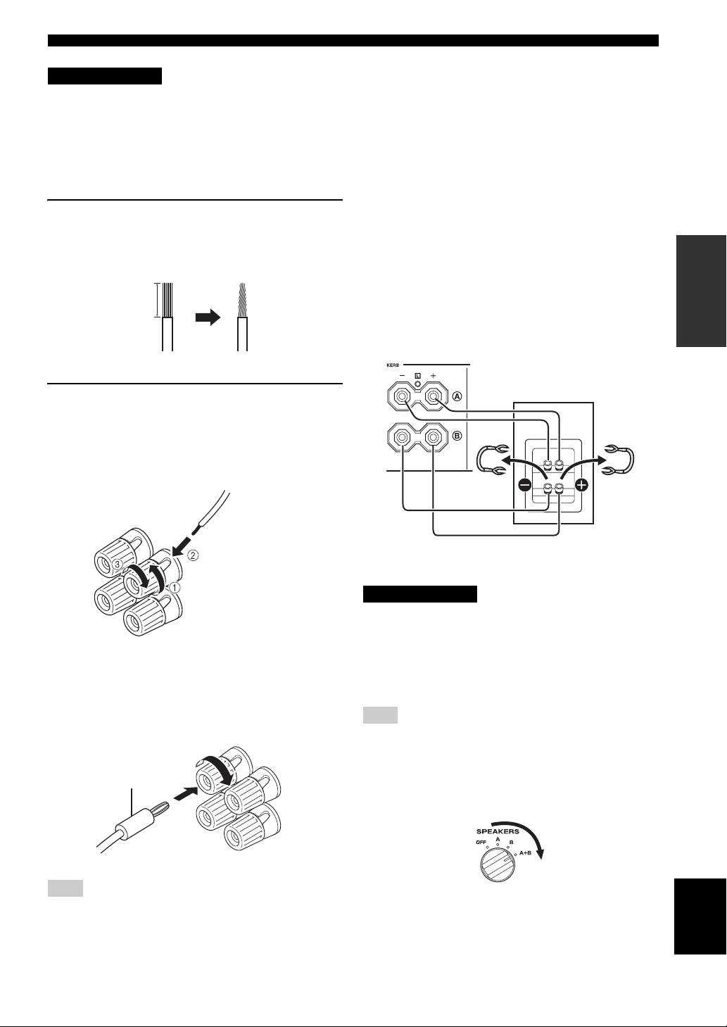
■ Bi-wire connection
1 Remove approximately 10 mm (3/8 in) of
The bi-wire connection separates the woofer from the
insulation from the end of each speaker
combined midrange and tweeter section. A bi-wire
PREPARATION
cable and twist the exposed wires of the
compatible speaker has four binding post terminals. These
two sets of terminals allow the speaker to be split into two
cable together to prevent short circuits.
independent sections. With these connections, the mid and
high frequency drivers are connected to one set of
10 mm (3/8 in)
terminals and the low frequency driver to another set of
terminals.
This unit
Speaker
2 Connect the speaker cable.
1 Unscrew the knob.
2 Insert one bare wire into the hole in the side
of each terminal.
3 Tighten the knob to secure the wire.
Red: positive (+)
Connect the other speaker to the other set of terminals in
Black: negative (–)
the same way.
CAUTION
When making bi-wire connections, set the IMPEDANCE
SELECTOR switch to HIGH or LOW depending on the
impedance of your speakers:
■ Connecting via banana plug
6 Ω or higher: HIGH
(Except for Asia, Korea, U.K. and Europe
4 Ω or higher: LOW
See page 5 for IMPEDANCE SELECTOR switch.
models)
First, tighten the knob and then insert the banana plug into
Note
the end of the corresponding terminal.
When making bi-wire connections, remove the shorting bridges
or cables on the speaker.
y
Banana plug
To use the bi-wire connections, switch the SPEAKERS selector
to the A+B position.
Note
English
One or two speaker sets can be connected to this unit.
7 En
CONNECTIONS
Connecting the supplied power cable
To the wall outlet with the
supplied power cable
(Asia and General models)
■ VOLTAGE SELECTOR
(Asia and General models only)
The VOLTAGE SELECTOR on the rear panel of this unit
must be set for your local main voltage BEFORE plugging
the supplied power cable into the wall outlet.
Improper setting of the VOLTAGE SELECTOR may
cause damage to this unit and create a potential fire
hazard.
Rotate the VOLTAGE SELECTOR clockwise or
counterclockwise to the correct position using a straight
slot screwdriver.
Voltages are as follows:
Asia model.......................... AC 220/230–240 V, 50/60 Hz
General model ......AC 110/120/220/230–240 V, 50/60 Hz
■ AC OUTLET(S) (SWITCHED)
U.K. and Australia models ..................................... 1 outlet
Korea model .............................................................. None
Other models ........................................................ 2 outlets
Use these outlets to connect the power cables from your
other components to this unit. The power to the AC
OUTLET(S) is controlled by POWER on the front panel
of this unit (or on the remote control). The outlet(s) supply
power to any connected component whenever the power
of this unit is turned on. For information on the maximum
power (total power consumption of components), see
“SPECIFICATIONS” on page 15.
Note
Do not connect components with a built-in amplifier, such as a
subwoofer, etc.
■ Connecting the supplied power cable
Plug the supplied power cable into the AC IN on the rear
panel of this unit and then, plug the power cable into the
wall outlet after all other connections are complete.
8 En
OPERATION
PLAYING AND RECORDING
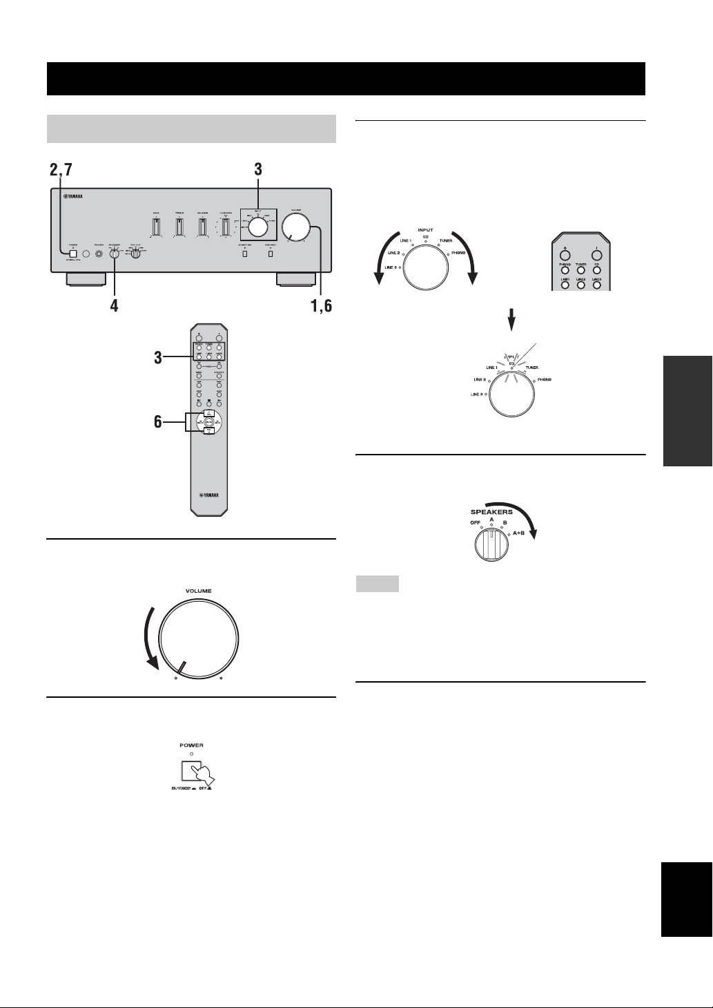
Playing a source
3 Rotate the INPUT selector on the front panel
(or press one of the input selector buttons on
the remote control) to select the input source
you want to listen to.
The indicator of the selected input source lights up.
or
Front panel Remote control
Lights up
OPERATION
4 Rotate the SPEAKERS selector on the front
panel to select SPEAKERS A, B or A+B.
1 Rotate VOLUME on the front panel to the
extreme counterclockwise position.
Notes
• Switch the SPEAKERS selector to the A+B position when
making bi-wire connections, or when using two sets of speakers
simultaneously (A and B).
• If you listen with headphones, rotate the selector to the OFF
position.
5 Play the source.
2 Press POWER on the front panel inward to
the ON position.
English
9 En
PLAYING AND RECORDING
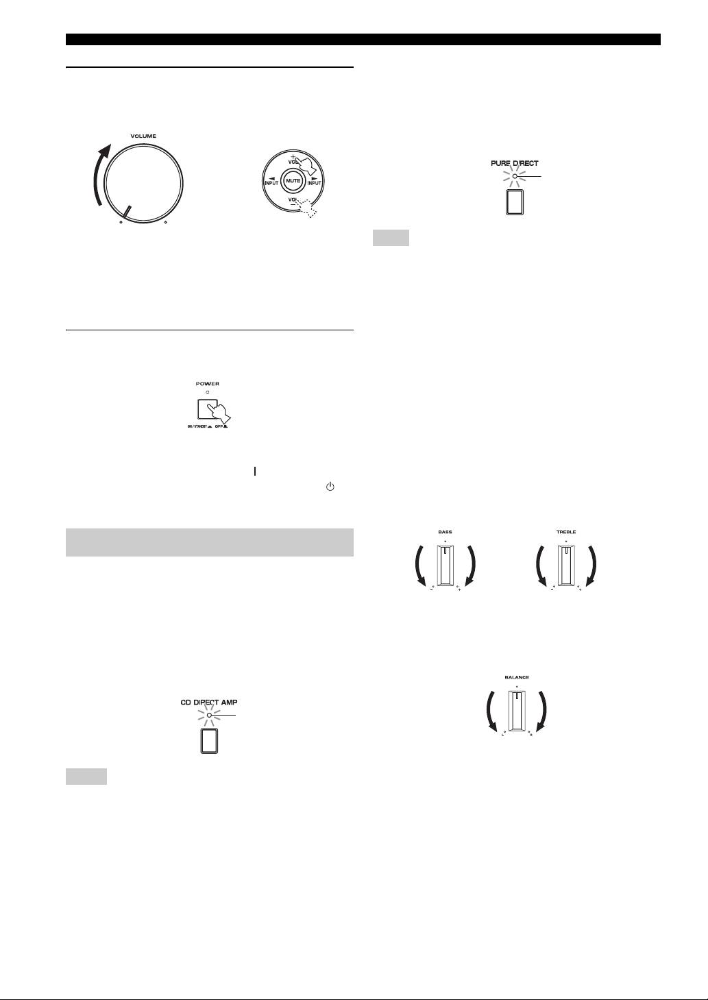
■ Using the PURE DIRECT switch
6 Rotate VOLUME on the front panel (or press
Routes input signals from your audio sources. As a result,
VOL +/– on the remote control) to adjust the
the input signals bypass the BASS, TREBLE, BALANCE
sound output level.
and LOUDNESS controls, thus eliminating any alterations
to the audio signals to produce more direct and high-grade
sound from all input sources.
Lights up
or
Remote controlFront panel
Note
The BASS, TREBLE, BALANCE and LOUDNESS controls do
y
not function while the PURE DIRECT switch is turned on.
You can adjust the tonal quality by using the BASS, TREBLE,
BALANCE and LOUDNESS controls, the CD DIRECT AMP
■ Adjusting the BASS and TREBLE
switch, or the PURE DIRECT switch on the front panel.
controls
Adjust the high and low frequency response.
7 After using, press POWER on the front panel
The center position produces a flat response.
to turn off the power.
BASS
When you feel a lack of bass sound, rotate clockwise to
boost. When you feel excessive bass sound, rotate
counterclockwise to suppress.
Control range: –10 dB to +10 dB (20 Hz)
y
TREBLE
You can turn on the power by pressing the button on the remote
When you feel a lack of treble sound, rotate clockwise to
control if you set this unit to standby mode by pressing the
boost. When you feel excessive treble sound, rotate
button on the remote control.
counterclockwise to suppress.
Control range: –10 dB to +10 dB (20 kHz)
Adjusting the tonal quality
■ Using the CD DIRECT AMP switch
Routes input signals directly to the power amplifier from
your CD player, regardless of the INPUT selector setting.
■ Adjusting the BALANCE control
As a result, the input signals bypass the INPUT selector
and the BASS, TREBLE, BALANCE and LOUDNESS
Adjust the sound output balance of the left and right
speakers to compensate for sound imbalance caused by
controls. The gain is also adjusted appropriately for CD so
that the purest possible sound is reproduced without any
speaker locations or listening room conditions.
alterations to the CD signals.
Lights up
Notes
• The BASS, TREBLE, BALANCE, LOUDNESS controls and
INPUT selector do not function while the CD DIRECT AMP
switch is turned on.
• Be sure to connect the CD player to the CD input jacks if you
use the CD DIRECT AMP switch.
10 En
PLAYING AND RECORDING
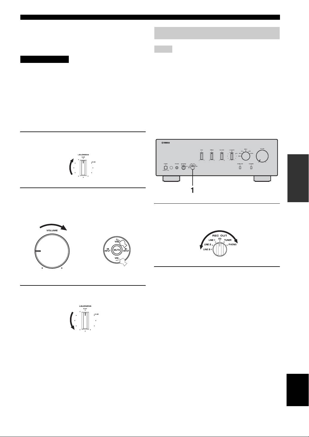
■ Adjusting the LOUDNESS control
Retain a full tonal range at any volume level, thus
Recording a source
compensating for the human ears’ loss of sensitivity to
high and low-frequency ranges at low volume.
Notes
CAUTION
• The audio signals are not output via the LINE 2 REC or LINE 3
REC output jacks when LINE 2 or LINE 3 is selected with the
If the CD DIRECT AMP switch (or the PURE DIRECT
REC OUT selector.
switch) is turned on with the LOUDNESS control set at a
The audio signals are output at both LINE 2 REC and LINE 3
certain level, the input signals bypass the loudness control,
REC output jacks if you select PHONO, TUNER, CD or LINE
resulting in a sudden increase in the sound output level. To
1.
• The VOLUME, BASS, TREBLE, BALANCE and
prevent your ears or the speakers from being damaged, be
LOUDNESS controls and the CD DIRECT AMP switch (and
sure to press the CD DIRECT AMP switch (or the PURE
the PURE DIRECT switch) have no effect on the source being
DIRECT switch) AFTER lowering the sound output level
recorded.
or AFTER checking that the LOUDNESS control is
• Check the copyright laws in your country to record from
properly set.
records, CDs, radio, etc. Recording copyright-protected
material may infringe on copyright laws.
1 Set the LOUDNESS control to the FLAT
position.
OPERATION
2 Rotate VOLUME on the front panel (or press
VOL +/– on the remote control) to set the
sound output level to the loudest listening
1 Rotate the REC OUT selector on the front
level that you would listen to.
panel to select the source you want to
record.
or
Remote controlFront panel
2 Play the source and begin recording on
recording device connected to the REC
output jacks (LINE 2 and/or LINE 3) on the
3 Rotate the LOUDNESS control until the
rear panel. See page 6.
desired volume is obtained.
y
• If you select the same source with the INPUT selector as you
select with the REC OUT selector, you can monitor the
recording.
• To listen to another input source without affecting the current
record out signal, select the source with the INPUT selector.
y
After setting the LOUDNESS control, enjoy listening to music at
your preferred volume level by controlling VOLUME. If the
effect of the loudness control is too strong or weak, readjust the
LOUDNESS control.
English
11 En
ADDITIONAL INFORMATION
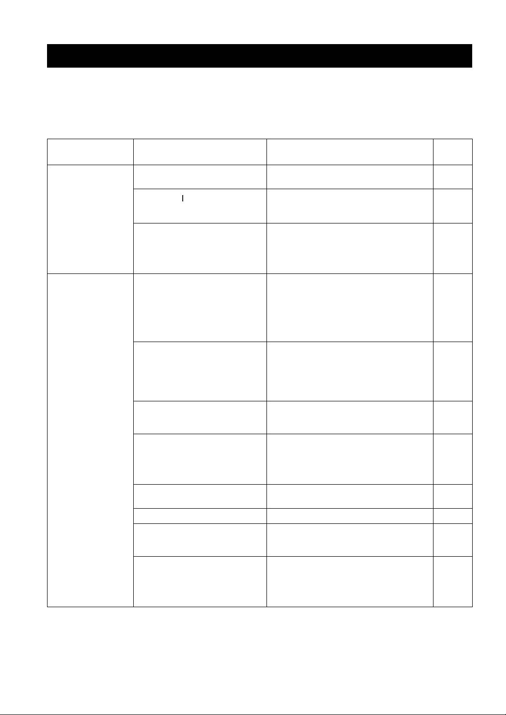
TROUBLESHOOTING
Refer to the chart below if this unit does not function properly. If the problem you are experiencing is not listed below or
if the instructions below do not help, set this unit to the standby mode, disconnect the power cable, and contact the
nearest authorized Yamaha dealer or service center.
■ General
Refer to
Problems Possible Causes Solutions
page
Pressing the POWER
The supplied power cable is not connected
Connect the supplied power cable firmly.
8
switch on the front
or the cable is not completely inserted.
panel does not turn
on this unit. The
The POWER ( ) button is pressed on the
Press POWER on the front panel to ON.
POWER on indicator
remote control while this unit is turned
3
also does not light up.
off.
There is a problem with the internal
Disconnect the AC power cable and contact the
circuitries of this unit.
nearest authorized Yamaha dealer or service center. If
an unusual odor or noise is generated from the unit,
—
do not turn on the power, disconnect the AC power
cable, and contact a service center for repair.
The power of this unit
The speaker wires are touching each other
Connect the speaker cables properly and press the
is turned off suddenly
or shorting out against the rear panel.
power button ON again. The VOLUME is decreased
and the POWER on
automatically and this unit is turned on after the
indicator blinks.
INPUT indicator blinks for about 15 seconds.
7
Confirm normal sound output from speakers by
increasing the volume gradually, then you can operate
This unit is turned off
this unit normally.
after several seconds
The speaker is a malfunction. Replace the speaker set and press the power button
of turning on, and the
ON again. The VOLUME is decreased automatically
POWER on indicator
and this unit is turned on after the INPUT indicator
blinks.
—
blinks for about 15 seconds. Confirm normal sound
output from speakers by increasing the volume
gradually, then you can operate this unit normally.
The protection circuitry has been activated
Rotate the VOLUME control on the front panel to
because of excessive input or excessive
decrease the volume level and then turn the power on
—
volume level.
again.
The protection circuitry has been activated
Allow about 30 minutes for the temperature inside
due to excessive internal temperature.
this unit to decrease, rotate the VOLUME control on
the front panel to lower the volume and then turn the
—
power on again. Set the unit in a place where heat can
readily dissipate from the unit.
The IMPEDANCE SELECTOR switch
Turn the power off and slide the IMPEDANCE
5
may not be fully slid to either position.
SELECTOR switch all the way to either position.
The impedance setting is incorrect. Set the impedance to match your speakers. 5
This unit has been exposed to a strong
Set this unit to the standby mode, disconnect the
external electric shock (such as lightning
power cable, plug it back in after 30 seconds, then use
—
or strong static electricity).
it normally.
There is a problem with the internal
Disconnect the AC power cable and contact the
circuitries of this unit.
nearest authorized Yamaha dealer or service center. If
an unusual odor or noise is generated from the unit,
—
do not turn on the power, disconnect the AC power
cable, and contact a service center for repair.
12 En

TROUBLESHOOTING
Refer to
Problems Possible Causes Solutions
page
No sound Sound is muted. Press MUTE on the remote control to resume the
3
audio output.
Incorrect cable connections. Connect the stereo cable for audio units and the
speaker wires properly. If the problem persists, the
6
cables may be defective.
No appropriate input source has been
Select an appropriate input source with the INPUT
selected.
selector on the front panel (or one of the input
9
selector buttons on the remote control).
The SPEAKERS selector is not set
Set the corresponding SPEAKERS selector to A, B or
9
properly.
A+B position.
The sound suddenly
The protection circuitry has been activated
Check that the IMPEDANCE SELECTOR setting is
5
goes off.
because of a short circuit, etc.
correct.
Check that the speaker wires are not touching each
other or shorting out against the rear panel of this
6
unit, and then turn the power of this unit back on.
Only the speaker on
Incorrect cable connections. Connect the cables properly. If the problem persists,
6
one side can be
the cables may be defective.
heard.
Incorrect setting for the BALANCE
Set the BALANCE control to the appropriate
10
control.
position.
There is a lack of
The + and – wires are connected in
Connect the speaker wires to the correct + and –
bass and no
reverse at the amplifier or the speakers.
phase. 6
ambience.
A “humming” sound
Incorrect cable connections. Connect the audio plugs firmly. If the problem
6
can be heard.
persists, the cables may be defective.
INFORMATION
No connection from the turntable to the
Make the GND connection between the turntable and
ADDITIONAL
6
GND terminal.
this unit.
The volume level is
The turntable is connected to the jacks
Connect the turntable to the PHONO jacks.
6
low while playing a
other than the PHONO jacks.
record.
The record is being played on a turntable
Use a turntable equipped with an MM cartridge.
—
with an MC cartridge.
The volume level
The component connected to LINE 2 REC
Turn on the power of the component.
cannot be increased,
or LINE 3 REC terminals of this unit is
—
or the sound is
turned off.
distorted.
The sound is
The power of this unit is turned off, or this
Turn on the power of this unit.
degraded when
unit is set to the standby mode.
listening with the
headphones
9
connected to the CD
player or the tape
deck connected to
this unit.
The sound level is
The LOUDNESS control is functioning. Set the LOUDNESS control to the FLAT position.
11
low.
The input source
The CD DIRECT AMP switch is turned
Turn off the CD DIRECT AMP switch.
cannot be changed
on.
10
although the INPUT
selector is rotated.
Using the BASS,
The CD DIRECT AMP switch or the
The CD DIRECT AMP switch or the PURE DIRECT
TREBLE, BALANCE
PURE DIRECT switch is turned on.
switch must be turned off to use those controls.
English
and LOUDNESS
10
controls does not
affect the tonal
quality.
13 En

TROUBLESHOOTING
■ Remote control
Refer to
Problems Possible Causes Solutions
page
The remote control
The remote control is too far away or
The remote control will function within a maximum
does not work nor
tilted too much.
range of 6 m (20 ft) and no more than 30 degrees off-
4
function properly.
axis from the front panel.
Direct sunlight or lighting (from an
Reposition this unit or lightning.
inverter type of fluorescent lamp, etc.) is
—
striking the remote control sensor of this
unit.
The batteries are weak. Replace all batteries. 4
14 En

SPECIFICATIONS
POWER SECTION
CONTROL SECTION
• Minimum RMS output power
• Input Sensitivity/Input Impedance
(8 Ω, 20 Hz to 20 kHz, 0.019% THD)...................... 90 W + 90 W
PHONO .................................................................. 3.0 mV/47 kΩ
(6 Ω, 20 Hz to 20 kHz, 0.03% THD).................... 105 W + 105 W
CD, etc. .................................................................. 200 mV/47 kΩ
• Dynamic Power (IHF)
• Output Level/Output Impedance
(8/6/4/2 Ω) ...................................................... 135/160/200/240 W
REC level ................................................... 200 mV/1.2 kΩ or less
• Maximum Output Power
• Headphone Output/Impedance
[Europe model only]
(Input 1 kHz, 200 mV, 8 Ω, 0.015% THD)
(1 kHz, 0.7% THD, 4 Ω) ................................................... 160 W
CD, etc. ................................................................ 0.47 V/470 Ω
[Asia and General models only] (JEITA)
• Channel Separation
(1 kHz, 10% THD, 8/6 Ω) .......................................... 140/160 W
CD, etc. (5.1 kΩ input shorted, 1/10 kHz) ........ 65/50 dB or more
• IEC Output Power [Europe model only]
• Tone Control Characteristics
(1 kHz, 0.019% THD, 8 Ω) ................................................. 105 W
BASS
• Power Band Width
Boost/Cut (20 Hz) .......................................................... ±10 dB
(0.03% THD, 50 W, 8 Ω) .................................... 10 Hz to 50 kHz
Turnover Frequency ........................................................ 350 Hz
TREBLE
• Damping Factor
Boost/Cut (20 kHz) ........................................................ ±10 dB
1 kHz, 8 Ω ................................................................... 240 or more
Turnover Frequency ....................................................... 3.5 kHz
• Maximum Input Signal
• Continuous Loudness Control
PHONO (1 kHz, 0.019% THD) ............................ 70 mV or more
Attenuation (1 kHz) ............................................................ –30 dB
CD, etc. (1 kHz, 0.019% THD) .............................. 2.2 V or more
• Frequency Response
GENERAL
CD, etc. (20 Hz to 20 kHz) ........................................... 0 ± 0.5 dB
• Power Supply
CD DIRECT AMP ON (10 Hz to 100 kHz) ................. 0 ± 1.0 dB
[U.S.A. and Canada models] ............................. AC 120 V, 60 Hz
• RIAA Equalization Deviation
[Asia model] .................................. AC 220/230–240 V, 50/60 Hz
PHONO ............................................................................ ± 0.5 dB
[General model] .............. AC 110/120/220/230–240 V, 50/60 Hz
[China model]......................................................AC 220 V, 50 Hz
• Total Harmonic Distortion
[Korea model] ..................................................... AC 220 V, 60 Hz
PHONO to OUT (REC)
INFORMATION
[Australia model] .............................................. AC 240 V, 50 Hz
ADDITIONAL
(20 Hz to 20 kHz, 3 V) ......................................... 0.008% or less
[U.K. and Europe models] ................................ AC 230 V, 50 Hz
CD, etc. to SP OUT
(20 Hz to 20 kHz, 50 W, 8 Ω) ............................... 0.012% or less
• Power Consumption
[U.S.A. and Canada models] ................................ 260 W, 360 VA
• Signal to Noise Ratio (IHF-A Network)
[Other models] ................................................................... 260 W
PHONO (5 mV input shorted) ................................ 87 dB or more
CD DIRECT AMP (200 mV input shorted) .......... 110 dB or more
• Standby Power Consumption .................................................. 0.1 W
• Residual Noise (IHF-A Network)
• Maximum Power Consumption [General model only]
CD DIRECT AMP ON ....................................................... 30 µV
(6 Ω, 1 kHz, 10% THD)...................................................... 650 W
PURE DIRECT ON .......................................................... 110 µV
•AC Outlets
• Gain Tracking Error (0 to –60 dB) ..................................2 dB or less
[U.K. and Australia models] .............. 1 (Total 100 W maximum)
[Korea model] ....................................................................... None
[General model] .....................................2 (Total 50 W maximum)
[Other models] ................................... 2 (Total 100 W maximum)
• Dimensions (W × H × D) ................................ 435 × 151 × 382 mm
(17-1/8 in × 5-15/16 in × 15-1/16 in)
• Weight..................................................................... 10.9 kg (24 lbs.)
Specifications are subject to change without notice.
English
15 En
Limited Guarantee for European Economic Area (EEA) and Switzerland
Thank you for having chosen a Yamaha product. In the unlikely event that your Yamaha product needs guarantee service, please contact the dealer from
whom it was purchased. If you experience any difficulty, please contact Yamaha representative office in your country. You can find full details on our
website (http://www.yamaha-hifi.com/ or http://www.yamaha-uk.com/ for U.K. resident).
The product is guaranteed to be free from defects in workmanship or materials for a period of two years from the date of the original purchase. Yamaha
undertakes, subject to the conditions listed below, to have the faulty product or any part(s) repaired, or replaced at Yamaha’s discretion, without any charge
for parts or labour. Yamaha reserves the right to replace a product with that of a similar kind and/or value and condition, where a model has been
discontinued or is considered uneconomic to repair.
Conditions
1. The original invoice or sales receipt (showing date of purchase, product code and dealer’s name) MUST accompany the defective product, along with a
statement detailing the fault. In the absence of this clear proof of purchase, Yamaha reserves the right to refuse to provide free of charge service and the
product may be returned at the customer’s expense.
2. The product MUST have been purchased from an AUTHORISED Yamaha dealer within the European Economic Area (EEA) or Switzerland.
3. The product must not have been the subject of any modifications or alterations, unless authorised in writing by Yamaha.
4. The following are excluded from this guarantee:
a. Periodic maintenance and repair or replacement of parts due to normal wear and tear.
b. Damage resulting from:
(1) Repairs performed by the customer himself or by an unauthorised third party.
(2) Inadequate packaging or mishandling, when the product is in transit from the customer. Please note that it is the customer’s responsibility to
ensure the product is adequately packaged when returning the product for repair.
(3) Misuse, including but not limited to (a) failure to use the product for its normal purpose or in accordance with Yamaha’s instructions on the
proper use, maintenance and storage, and (b) installation or use of the product in a manner inconsistent with the technical or safety standards in
force in the country where it is used.
(4) Accidents, lightning, water, fire, improper ventilation, battery leakage or any cause beyond Yamaha’s control.
(5) Defects of the system into which this product is incorporated and/or incompatibility with third party products.
(6) Use of a product imported into the EEA and/or Switzerland, not by Yamaha, where that product does not conform to the technical or safety
standards of the country of use and/or to the standard specification of a product sold by Yamaha in the EEA and/or Switzerland.
(7) Non AV (Audio Visual) related products.
(Products subject to “Yamaha AV Guarantee Statement” are defined in our website at http://www.yamaha-hifi.com/ or
http://www.yamaha-uk.com/ for U.K. resident.)
5. Where the guarantee differs between the country of purchase and the country of use of the product, the guarantee of the country of use shall apply.
6. Yamaha may not be held responsible for any losses or damages, whether direct, consequential or otherwise, save for the repair or replacement of the
product.
7. Please backup any custom settings or data, as Yamaha may not be held responsible for any alteration or loss to such settings or data.
8. This guarantee does not affect the consumer’s statutory rights under applicable national laws in force or the consumer’s rights against the dealer arising
from their sales/purchase contract.
Information for Users on Collection and Disposal of Old Equipment
and Used Batteries
These symbols on the products, packaging, and/or accompanying documents mean that used electrical and
electronic products and batteries should not be mixed with general household waste.
For proper treatment, recovery and recycling of old products and used batteries, please take them to
applicable collection points, in accordance with your national legislation and the Directives 2002/96/EC
and 2006/66/EC.
By disposing of these products and batteries correctly, you will help to save valuable resources and prevent
any potential negative effects on human health and the environment which could otherwise arise from
inappropriate waste handling.
For more information about collection and recycling of old products and batteries, please contact your
local municipality, your waste disposal service or the point of sale where you purchased the items.
[Information on Disposal in other Countries outside the European Union]
These symbols are only valid in the European Union. If you wish to discard these items, please contact
your local authorities or dealer and ask for the correct method of disposal.
Note for the battery symbol (bottom two symbol examples):
This symbol might be used in combination with a chemical symbol. In this case it complies with the
requirement set by the Directive for the chemical involved.

ATTENTION : VEUILLEZ LIRE CE QUI SUIT AVANT D’UTILISER
L’APPAREIL.
1 Pour utiliser l’appareil au mieux de ses possibilités, lisez
14 Ne tentez pas de modifier ni de réparer l’appareil. Consultez
attentivement ce mode d’emploi. Conservez-le soigneusement
le service Yamaha compétent pour toute réparation qui serait
pour référence.
requise. Le coffret de l’appareil ne doit jamais être ouvert,
2 Installez cet appareil audio dans un endroit bien aéré, frais,
quelle que soit la raison.
sec et propre – à l’abri de la lumière directe du soleil, des
15 Si vous envisagez de ne pas vous servir de l’appareil pendant
sources de chaleur ou de vibration, des poussières, de
une longue période (par exemple, pendant les vacances),
l’humidité et du froid. Ménagez un espace libre d’au moins
débranchez la fiche du cordon d’alimentation au niveau de la
30 cm au-dessus, 20 cm sur la gauche et la droite et 20 cm à
prise secteur.
l’arrière de l’appareil pour qu’il soit bien ventilé.
16 Installez cet appareil à proximité de la prise secteur et à un
3 Placez l’appareil loin des équipements, moteurs et
emplacement où la fiche d’alimentation est facilement
transformateurs électriques, pour éviter les ronflements
accessible.
parasites.
17 Lisez la section intitulée « GUIDE DE DÉPANNAGE » où
4 N’exposez pas l’appareil à des variations brutales de
figurent une liste d’erreurs de manipulation ordinaires avant
température, ne le placez pas dans un environnement très
de conclure à une anomalie une anomalie de l’appareil.
humide (par exemple dans une pièce contenant un
18 Avant de déplacer cet appareil, appuyez sur POWER pour le
humidificateur) car cela peut entraîner la condensation
mettre hors tension, puis débranchez le cordon d’alimentation
d’humidité à l’intérieur de l’appareil qui elle-même peut être
de la prise murale.
responsable de secousse électrique, d’incendie, de dommage à
19 VOLTAGE SELECTOR
l’appareil ou de blessure corporelle.
(Modèles pour l’Asie et Standard uniquement)
5 Evitez d’installer l’appareil dans un endroit où des objets
Le sélecteur VOLTAGE SELECTOR situé sur le panneau
peuvent tomber, ainsi que là où l’appareil pourrait être exposé
arrière de cet appareil doit être réglé sur votre tension secteur
à des éclaboussures ou des gouttes d’eau. Sur le dessus de
locale AVANT le raccordement à la prise murale. Les
l’appareil, ne placez pas :
tensions sont les suivantes :
– D’autres appareils qui peuvent endommager la surface de
Modèle pour l’Asie .................. CA 220/230–240 V, 50/60 Hz
l’appareil ou provoquer sa décoloration.
Modèle Standard ........ CA 110/120/220/230–240 V, 50/60 Hz
– Des objets se consumant (par exemple, une bougie) qui
20 Les piles ne doivent pas être exposées à une chaleur extrême,
peuvent être responsables d’incendie, de dommage à
par exemple au soleil, à une flamme, etc.
l’appareil ou de blessure corporelle.
21 Une pression excessive du son par les écouteurs et le casque
–
Des récipients contenant des liquides qui peuvent être à
d’écoute peut entraîner la perte de l’ouïe.
l’origine de secousse électrique ou de dommage à l’appareil.
6 Ne couvrez pas l’appareil d’un journal, d’une nappe, d’un
Aussi longtemps que cet appareil est raccordé à la
rideau, etc. car cela empêcherait l’évacuation de la chaleur.
prise murale, il n’est pas débranché de la source
Toute augmentation de la température intérieure de l’appareil
d’alimentation secteur même si vous le mettez hors
peut être responsable d’incendie, de dommage à l’appareil ou
tension à l’aide de la touche POWER ou le mettez en
de blessure corporelle.
mode veille à l’aide de la touche de la
7 Ne branchez pas la fiche du cordon d’alimentation de
télécommande.
l’appareil sur une prise secteur aussi longtemps que tous les
raccordements n’ont pas été effectués.
AVERTISSEMENT
8 Ne pas faire fonctionner l’appareil à l’envers. Il risquerait de
chauffer et d’être endommagé.
POUR RÉDUIRE LES RISQUES D’INCENDIE OU
9 N’exercez aucune force excessive sur les commutateurs, les
DE SECOUSSE ÉLECTRIQUE, N’EXPOSEZ PAS
boutons et les cordons.
CET APPAREIL À LA PLUIE OU À L’HUMIDITÉ.
10
Pour débrancher la fiche du cordon d’alimentation au niveau de
la prise secteur, saisissez la fiche et ne tirez pas sur le cordon.
Cette appareil passe en mode veille lorsque vous
11 Ne nettoyez pas cet appareil à l’aide de solvants chimiques, au
enfoncez POWER en position ON, puis appuyez sur la
risque d’endommager la finition. Utilisez un chiffon propre et
touche de la télécommande. Dans cet état, l’appareil
sec.
est conçu pour consommer une très faible quantité de
12 N’alimentez l’appareil qu’à partir de la tension prescrite.
courant.
Alimenter l’appareil sous une tension plus élevée est
dangereux et peut être responsable d’incendie, de dommage à
l’appareil ou de blessure corporelle. Yamaha ne saurait être
tenue responsable des dommages résultant de l’alimentation
de l’appareil sous une tension autre que celle prescrite.
13 Pour éviter tout dégât dû à la foudre, débranchez le cordon
d’alimentation de la prise murale ou de l’appareil pendant un
orage.
i Fr
