Yamaha A-S700: Rear panel
Rear panel: Yamaha A-S700
Table of contents
- CAUTION: READ THIS BEFORE OPERATING YOUR UNIT.
- CONTENTS FEATURES SUPPLIED ACCESSORIES
- CONTROLS AND FUNCTIONS Front panel
- Remote control
- Installing batteries in the remote Using the remote control control
- Rear panel
- Connecting speakers and other components CAUTION
- ■ Bi-wire connection CAUTION ■ Connecting via banana plug
- Connecting the supplied power cable
- Playing a source
- ■ Using the PURE DIRECT switch ■ Adjusting the BASS and TREBLE controls Adjusting the tonal quality ■ Using the CD DIRECT AMP switch
- ■ Adjusting the LOUDNESS control Recording a source
- TROUBLESHOOTING ■ General Problems Possible Causes Solutions
- Problems Possible Causes Solutions
- ■ Remote control Problems Possible Causes Solutions
- SPECIFICATIONS
CONTROLS AND FUNCTIONS
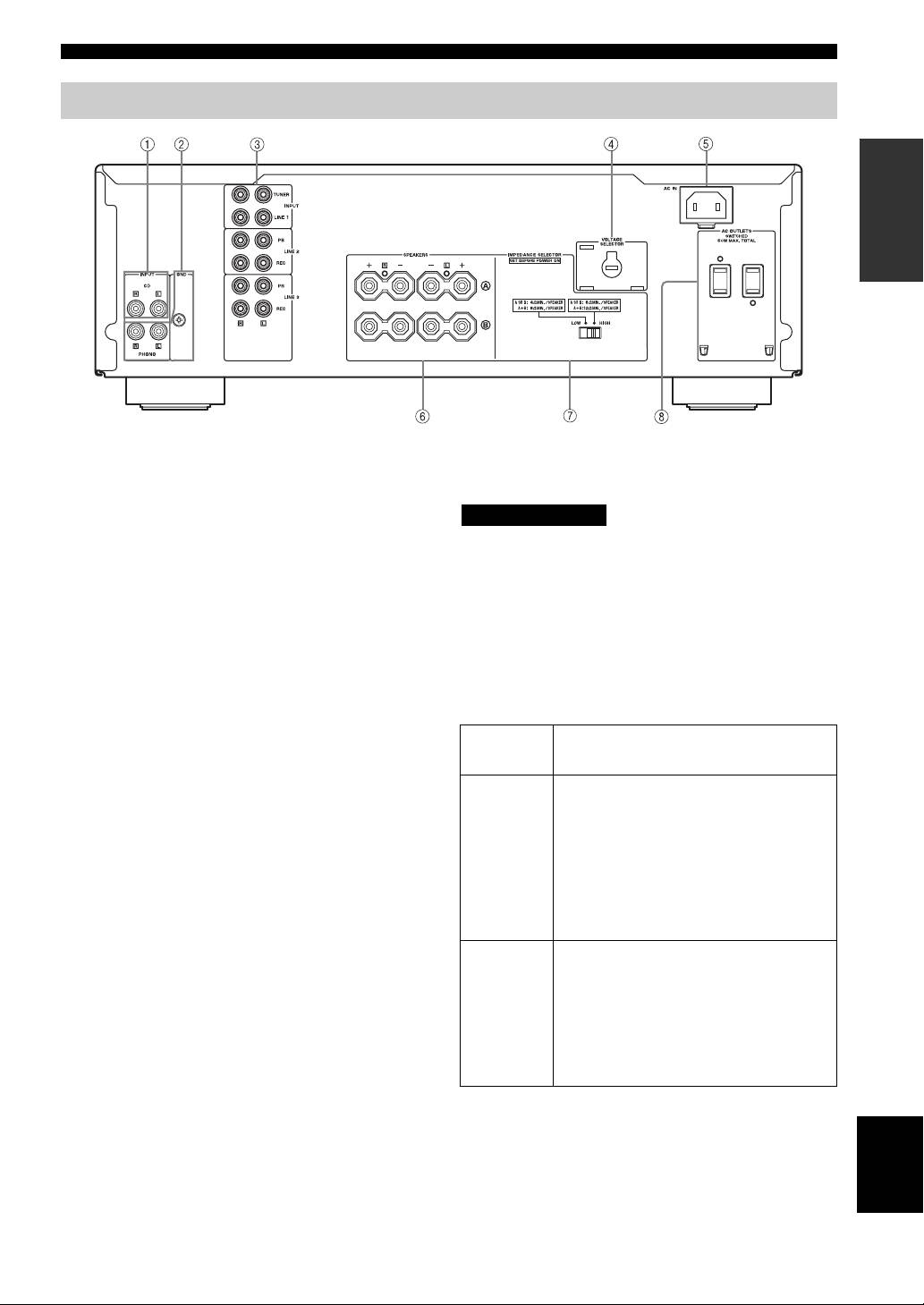
Rear panel
INTRODUCTION
(Asia and General models)
1 CD input jacks
■ IMPEDANCE SELECTOR switch
Connect a CD player.
CAUTION
See page 6 for connection information.
Do not change the IMPEDANCE SELECTOR switch
2 PHONO jacks and GND terminal
while the power of this unit is turned on, as doing so may
The PHONO jacks are designed to connect a turntable
damage the unit.
with an MM cartridge.
If the unit fails to turn on, the IMPEDANCE SELECTOR
See page 6 for connection information.
switch may not be fully slid to either position. If this is the
3 Audio input/output jacks
case, slide the switch all the way to either position when
Connect external components, such as a tuner, etc.
this unit’s power supply is completely cut off.
See page 6 for connection information.
Select the switch position (LOW or HIGH) according to
the impedance of the speakers in your system.
4 VOLTAGE SELECTOR
(Asia and General models only)
Switch
Impedance level
The VOLTAGE SELECTOR must be set to your local
position
main voltage before plugging the supplied power cable
• If you use one set (A or B), the impedance of
into the wall outlet.
the speaker must be 6
Ω or higher.
See page 8 for details.
• If you use two sets (A and B) simultaneously,
the impedance of each speaker must be 12
Ω
5 AC IN
HIGH
or higher. (Except for U.S.A and Canada
Use to plug in the supplied power cable.
models)
See page 8 for connection information.
• If you make bi-wire connections, the
impedance of the speaker must be 6
Ω or
6 SPEAKERS terminals
higher. See page 7 for details.
Connect one or two speaker sets.
• If you use one set (A or B), the impedance of
See page 6 for connection information.
the speaker must be 4
Ω or higher.
• If you use two sets (A and B) simultaneously,
7 IMPEDANCE SELECTOR switch
the impedance of each speaker must be 8
Ω or
See IMPEDANCE SELECTOR switch on this page.
LOW
higher.
• If you make bi-wire connections, the
8 AC OUTLET(S)
impedance of the speaker must be 4
Ω or
Use to supply power to your other audio/video
higher. See page 7 for details.
components.
See page 8 for details.
English
5 En
