Yamaha RX-V1065 Black: инструкция
Раздел: Видео Аудио Фото Оборудование
Тип: Ресивер
Характеристики, спецификации
Инструкция к Ресиверу Yamaha RX-V1065 Black

F
RX-V1065
AV R e c e i ve r
OWNER’S MANUAL
ИНСТРУКЦИЯ ПО ЭКСПЛУАТАЦИИ
Caution: Read this before operating your unit.
1 To assure the finest performance, please read this manual
17 Be sure to read the “Troubleshooting” section on common
carefully. Keep it in a safe place for future reference.
operating errors before concluding that this unit is faulty.
2 Install this sound system in a well ventilated, cool, dry, clean
18 Before moving this unit, press KMAIN ZONE ON/OFF to
place – away from direct sunlight, heat sources, vibration,
set this unit to the standby mode, and disconnect the AC
dust, moisture, and/or cold. Allow ventilation space of at least
power plug from the wall outlet in the main room.
30 cm on the top, 20 cm on the left and right, and 20 cm on
19
VOLTAGE SELECTOR (Asia and General models only)
the back of this unit.
The VOLTAGE SELECTOR on the rear panel of this unit
3 Locate this unit away from other electrical appliances, motors,
must be set for your local main voltage BEFORE plugging
or transformers to avoid humming sounds.
into the AC wall outlet. Voltages are:
4 Do not expose this unit to sudden temperature changes from
..... AC 110/120/220/230-240 V, 50/60 Hz (General model)
cold to hot, and do not locate this unit in an environment with
.........................AC 220/230-240 V, 50/60 Hz (Asia model)
high humidity (i.e. a room with a humidifier) to prevent
20 The batteries shall not be exposed to excessive heat such as
condensation inside this unit, which may cause an electrical
sunshine, fire or like.
shock, fire, damage to this unit, and/or personal injury.
21 Excessive sound pressure from earphones and headphones can
5 Avoid installing this unit where foreign objects may fall onto
cause hearing loss.
this unit and/or this unit may be exposed to liquid dripping or
22 When replacing the batteries, be sure to use batteries of the
splashing. On the top of this unit, do not place:
same type. Danger of explosion may happen if batteries are
– Other components, as they may cause damage and/or
incorrectly replaced.
discoloration on the surface of this unit.
WARNING
– Burning objects (i.e. candles), as they may cause fire,
TO REDUCE THE RISK OF FIRE OR ELECTRIC
damage to this unit, and/or personal injury.
– Containers with liquid in them, as they may fall and liquid
SHOCK, DO NOT EXPOSE THIS UNIT TO RAIN
may cause electrical shock to the user and/or damage to
OR MOISTURE.
this unit.
6 Do not cover this unit with a newspaper, tablecloth, curtain,
As long as this unit is connected to the AC wall outlet,
etc. in order not to obstruct heat radiation. If the temperature
it is not disconnected from the AC power source even
inside this unit rises, it may cause fire, damage to this unit,
if you turn off this unit by KMAIN ZONE ON/OFF.
and/or personal injury.
In this state, this unit is designed to consume a very
7 Do not plug in this unit to a wall outlet until all connections
small quantity of power.
are complete.
8 Do not operate this unit upside-down. It may overheat,
■ For U.K. customers
possibly causing damage.
If the socket outlets in the home are not suitable for the
9 Do not use force on switches, knobs and/or cords.
plug supplied with this appliance, it should be cut off and
10 When disconnecting the power cable from the wall outlet,
an appropriate 3 pin plug fitted. For details, refer to the
grasp the plug; do not pull the cable.
instructions described below.
11 Do not clean this unit with chemical solvents; this might
damage the finish. Use a clean, dry cloth.
Note
12 Only voltage specified on this unit must be used. Using this
The plug severed from the mains lead must be destroyed, as a
unit with a higher voltage than specified is dangerous and may
plug with bared flexible cord is hazardous if engaged in a live
cause fire, damage to this unit, and/or personal injury. Yamaha
socket outlet.
will not be held responsible for any damage resulting from use
■ Special Instructions for U.K. Model
of this unit with a voltage other than specified.
13 To prevent damage by lightning, keep the power cord and
IMPORTANT
outdoor antennas disconnected from a wall outlet or the unit
THE WIRES IN MAINS LEAD ARE COLOURED IN
during a lightning storm.
ACCORDANCE WITH THE FOLLOWING CODE:
14 Do not attempt to modify or fix this unit. Contact qualified
Yamaha service personnel when any service is needed. The
Blue: NEUTRAL
cabinet should never be opened for any reasons.
Brown: LIVE
15 When not planning to use this unit for long periods of time
As the colours of the wires in the mains lead of this apparatus
(i.e. vacation), disconnect the AC power plug from the wall
may not correspond with the coloured markings identifying
outlet.
the terminals in your plug, proceed as follows:
The wire which is coloured BLUE must be connected to the
16 Install this unit near the AC outlet and where the AC power
terminal which is marked with the letter N or coloured
plug can be reached easily.
BLACK. The wire which is coloured BROWN must be
connected to the terminal which is marked with the letter L or
coloured RED.
Making sure that neither core is connected to the earth
terminal of the three pin plug.
Caution-i En

Contents
Using Bluetooth™ components ........................... 36
INTRODUCTION
Pairing the Bluetooth™ wireless audio receiver
and your Bluetooth component............................ 36
Features....................................................................2
INTRODUCTION
Playback of the Bluetooth™ component ................. 36
About this manual................................................... 3
Using USB storage devices................................... 37
Supplied accessories................................................3
Playback of the USB storage device........................ 37
Part names and functions....................................... 4
Other functions ..................................................... 38
Front panel ................................................................. 4
Using the sleep timer ............................................... 38
Rear panel .................................................................. 5
Using the HDMI™ control function........................ 38
Front panel display..................................................... 6
Remote control........................................................... 7
ADVANCED OPERATION
Quick start guide..................................................... 8
L
Setting the option menu for each input source
PREPARATION
(Option menu)................................................... 39
PREPARATION
Option menu items................................................... 39
Preparing remote control ....................................... 9
Selecting a video signal to be output during an
Installing batteries in the remote control ................... 9
audio reproduction............................................... 41
Using the remote control............................................ 9
Editing surround decoders/
Connections ........................................................... 10
sound field programs........................................ 42
Placing speakers....................................................... 10
Setting sound field parameters................................. 42
Connecting speakers ................................................ 11
Sound field parameters ............................................ 42
Information on jacks and cable plugs ...................... 13
Operating various settings for this unit
Connecting a TV monitor or projector .................... 14
Connecting other components ................................. 15
(Setup menu) ..................................................... 46
Connecting a Yamaha iPod universal dock or
Basic operation of the Setup menu .......................... 47
OPERATION
Bluetooth™ wireless audio receiver.................... 17
Speaker Setup .......................................................... 47
BASIC
Connecting a USB storage device ........................... 18
Sound Setup ............................................................. 49
Using the VIDEO AUX jacks.................................. 18
Function Setup ......................................................... 50
Connecting the FM and AM antennas ..................... 18
DSP Parameter ......................................................... 52
Connecting the power cable..................................... 19
Memory Guard......................................................... 52
Turning this unit on and off ..................................... 19
Using multi-zone configuration ........................... 53
Optimizing the speaker setting for your
Connecting Zone2.................................................... 53
listening room (YPAO) .....................................20
Controlling Zone2.................................................... 54
Using Auto Setup..................................................... 20
Controlling other components with the remote
OPERATION
ADVANCED
When an error message is displayed during
control................................................................ 55
measurement ........................................................ 22
Setting remote control codes.................................... 55
When a warning message is displayed after
Resetting all remote control codes........................... 55
measurement ........................................................ 22
Programming from other remote controls ............... 56
Advanced setup..................................................... 57
BASIC OPERATION
APPENDIX
Playback.................................................................23
Basic procedure........................................................ 23
Troubleshooting.................................................... 59
Using the SCENE function ...................................... 23
Glossary ................................................................. 68
INFORMATION APPENDIX
ADDITIONAL
Selecting a source on the GUI screen ...................... 24
Sound field program information ....................... 70
Muting audio output................................................. 24
Information on HDMI™...................................... 71
Adjusting high/low frequency sounds
Specifications......................................................... 72
(tone control) ....................................................... 24
Index ...................................................................... 73
Enjoying pure hi-fi sound ........................................ 24
Using your headphones............................................ 25
(at the end of this manual)
Displaying input signal information ........................ 25
Changing information on the front panel display .... 25
Information about software.................................... i
Enjoying the sound field programs ..................... 26
List of remote control codes................................... ii
Selecting sound field programs................................ 26
Enjoying unprocessed input sources
(Straight decode mode)........................................ 29
Enjoying sound field programs without surround
speakers (Virtual CINEMA DSP) ....................... 29
Enjoy sound field programs with headphones
(SILENT CINEMA™) ........................................ 29
Using CINEMA DSP 3D mode ............................... 29
FM/AM tuning ...................................................... 30
Tuning in to the desired FM/AM station
(Frequency tuning) .............................................. 30
Registering FM/AM stations and tuning in
(Preset tuning)...................................................... 30
Radio Data System tuning.................................... 32
Displaying the Radio Data System information ...... 32
Selecting the Radio Data System program type
English
(PTY Seek) .......................................................... 32
Using the enhanced other networks (EON) data
service.................................................................. 33
Using iPod™ ..........................................................34
Controlling iPod™................................................... 34
1 En

INTRODUCTION
Features
■ Built-in 7-channel power amplifier
■ Digital audio decoders
• Minimum RMS Output Power (20 Hz to 20 kHz, 0.08%
• Dolby TrueHD, Dolby Digital Plus decoder
THD, 8 Ω)
• DTS-HD Master Audio, DTS-HD High Resolution
• FRONT L/R: 105 W + 105 W
Audio, DTS Express
• CENTER: 105 W
• Dolby Digital/Dolby Digital EX decoder
• SURROUND L/R: 105 W + 105 W
• DTS, DTS 96/24 decoder, DTS-ES Matrix 6.1, DTS-ES
• SURROUND BACK L/R: 105 W + 105 W
Discrete 6.1
• Dolby Pro Logic/Dolby Pro Logic II/Dolby Pro Logic
■ Speaker/Preout outputs
IIx decoder
• Speaker terminals (7-channel), extra speaker terminals
• DSD decoder
(2-channel for presence or Zone2), preout jacks (7.1-
•
DTS NEO:6 decoder
channel)
■ Sophisticated FM/AM tuner
■ Input/Output terminals
• 40-station random and direct preset tuning
Input terminals
• Automatic preset tuning
• HDMI input x 4
• Radio Data System tuning
• Audio/Visual input
■
HDMI™ (High-Definition Multimedia Interface)
[Audio] Digital input (coaxial) x 2, digital input
• HDMI interface for standard, enhanced or high-
(optical) x 2, analog input x 2
definition video as well as multi-channel digital audio.
[Video] Component video x 2, S-video x 1, Video x 4
– Automatic audio and video synchronization (lip sync)
• Audio input (analog) x 2
information capability
• Phono input (analog) x 1
– Deep Color video signal (30/36 bit) transmission
• Multi-channel audio input (7.1-channel)
capability
• V-AUX input
– “x.v.Color” video signal transmission capability
[Audio] Analog x 1
– High refresh rate and high resolution video signals
[Video] Video x 1
capability
• DOCK terminal to connect a Yamaha iPod universal
– High definition digital audio format signals capability
dock (such as YDS-11, sold separately) or Bluetooth
• Analog to analog and HDMI digital video up-
wireless audio receiver (such as YBA-10, sold
conversion (video ↔ component video → HDMI)
separately)
capability for monitor out
• USB port to connect a USB storage device
•
Analog video input up-scaling for HDMI digital video
Output terminals
output 480i(576i) or 480p(576p)
→
720p, 1080i or 1080p
• Monitor output
• HDMI control function supported
[Audio/Video] HDMI x 1
■ Automatic speaker setup features
[Video] Component video x 1, Video x 1
• “YPAO” (Yamaha Parametric Room Acoustic
• Audio/Visual output
Optimizer) for automatically optimizing speaker
[Audio] Analog x 1
outputs suitable for listening environments.
[Video] Video x 1
• Audio output
■ Other features
Analog x 1
• 192-kHz/24-bit D/A converter
• Zone2 output
• GUI (graphic user interface) menus to optimize this unit
Analog x 1
to suit individual audiovisual system
• iPod and USB file browsing and album art display
Other terminals
capability
Remote input x 1, Remote output x 1
• Pure Direct mode for pure hi-fi sound for all sources
Trigger output x 1
• Adaptive dynamic range controlling capability
■ Proprietary Yamaha technology for the
• SCENE function for changing input sources and sound
creation of sound fields
field programs with one key
• CINEMA DSP 3D
• Bi-amplification connection capability
• Compressed Music Enhancer mode
• Sleep timer
• Virtual CINEMA DSP
• Multi-zone function
• SILENT CINEMA
2 En

About this manual
• Some operations can be performed by using either the keys on the front panel or the ones on the remote control. In case the key names differ between
the front panel and the remote control, the key name on the remote control is given in parentheses.
• This manual is printed prior to production. Design and specifications are subject to change in part as a result of improvements, etc. In case of
INTRODUCTION
differences between the manual and product, the product has priority.
• For better viewing, we increase the size of characters used in example screen images in this manual. Therefore the size ratio of characters to other
objects (such as icons) may be different from that of the actual display image.
• “KMAIN ZONE ON/OFF” or “dHDMI 1” (example) indicates the name of the parts on the front panel or the remote control. Refer to the
attached sheet or “Part names and functions” (page 4).for the information about each position of the parts.
• ☞ indicates the page describing the related information.
• y indicates a tip for your operation.
Bluetooth
™
Bluetooth is a registered trademark of Bluetooth SIG and is used by
PREPARATION
Yamaha in accordance with a license agreement.
Manufactured under license from Dolby Laboratories.
Dolby, Pro Logic and the double-D symbol are trademarks of Dolby
Laboratories
“HDMI”, the “HDMI” logo and “High-Definition Multimedia
Interface” are trademarks, or registered trademarks of HDMI
Licensing LLC.
Manufactured under license under U.S. Patent No’s:
x.v.Color
OPERATION
5,451,942;5,956,674;5,974,380;5,978,762;6,226,616;6,487,535 &
“x.v.Color” is a trademark of Sony Corporation.
other U.S. and worldwide patents issued & pending. DTS is a
BASIC
registered trademark and the DTS logos, Symbol, DTS-HD and DTS-
HD Master Audio are trademark of DTS, Inc. © 1996-2007 DTS, Inc.
All Rights Reserved.
“SILENT CINEMA” is a trademark of Yamaha Corporation.
iPod™
“iPod” is a trademark of Apple Inc., registered in the U.S. and other
countries.
OPERATION
ADVANCED
Supplied accessories
Check that you received all of the following parts.
• Remote control (page 7)
• Batteries (2) (AAA, R03, UM-4) (page 9)
• Optimizer microphone (page 20)
INFORMATION APPENDIX
ADDITIONAL
• AM loop antenna (page 18)
• Indoor FM antenna (page 18)
English
3 En
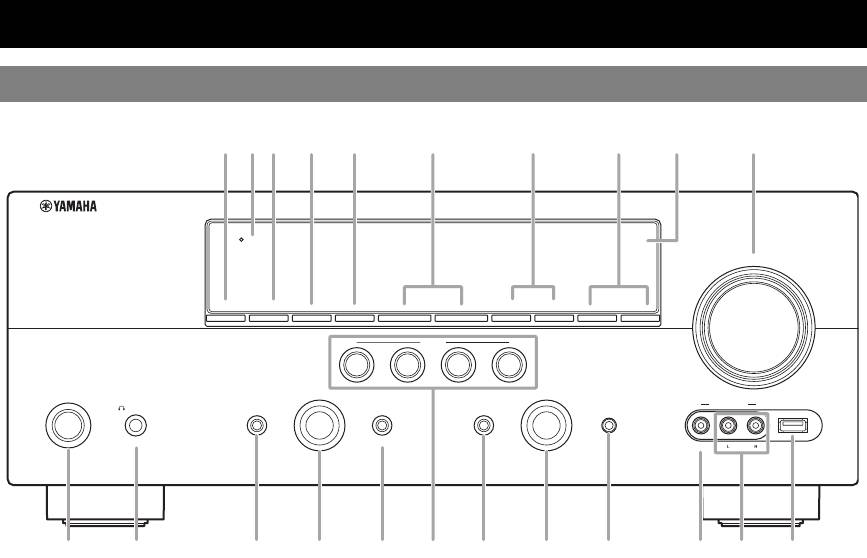
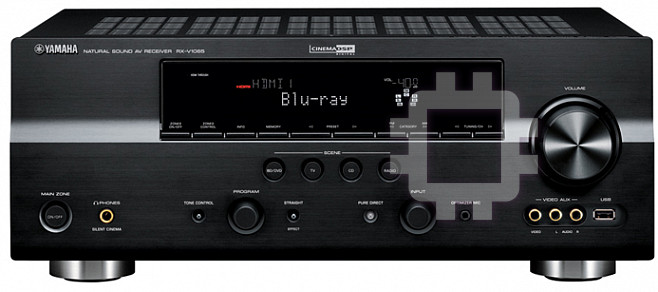
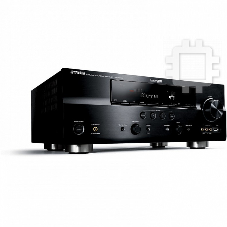
Part names and functions
Front panel
HDMI
THROUGH
VOLUME
ON/OFF
ZONE2
CONTROL
ZONE2
INFO
MEMORY
l
PRESET
h
FM AM TUNING
l
h
SCENE
BD/DVD
TV
CD
RADIO
MAIN
ZONE
PROGRAM
INPUT
PHONES
TONE
CONTROL
STRAIGHT
PURE DIRECT
OPTIMIZER
MIC
VIDEO
AUX
USB
ON/OFF
SILENT
CINEMA
EFFECT
VIDEO
AUDIO
A ZONE2 ON/OFF
N PROGRAM selector
Switches the zone function on and off (page 54).
Changes sound field programs (page 26).
B HDMI THROUGH
O STRAIGHT
Lights up in the following cases while this unit is on standby.
Toggles between the selected sound field program and straight
• when the HDMI control function is on
decode mode (page 29).
• when the HDMI signal standby-through function is currently
P SCENE
working
Switches between linked sets of input sources and sound field
C ZONE2 CONTROL
programs (page 23).
Enables operation of a receiver set in Zone2, including input
Q PURE DIRECT
source switching, volume control and tuner operation, with the
Changes mode to Pure Direct mode (page 24). This key lights up
main amplifier or remote control after this key is pressed
when Pure Direct mode is on.
(page 54).
R INPUT selector
D INFO
Selects an input source (page 23).
Changes information (input, DSP program, audio decoder, etc)
S OPTIMIZER MIC jack
displayed on the front panel display (page 25).
For connecting the supplied optimizer microphone and adjusting
E MEMORY
output characteristics of speakers (page 20).
Registers FM/AM stations as preset stations (page 31).
T VIDEO (VIDEO AUX) jack
F PRESET l / h
For connecting the video output cable of a camcorder or game
Selects an FM/AM preset station (page 31).
console (page 18).
G FM/AM
U AUDIO L/R (VIDEO AUX) jack
Change the tuner bands between FM and AM.
For connecting the audio output cable of a camcorder or game
H TUNING l / h
console (page 18).
Changes FM/AM frequencies.
V USB port
I Front panel display
For connecting a USB memory device or USB portable audio
Displays information on this unit (page 6).
player (page 18)
J VOLUME control
Controls the volume of this unit (page 23).
K MAIN ZONE ON/OFF
Turns this unit on and off (page 19).
L PHONES jack
For plugging headphones (page 25).
M TONE CONTROL
Adjusts high-frequency/low-frequency output of speakers
(page 24).
4 En
ABC D E F G H I J
KNQMO R
SULPTV
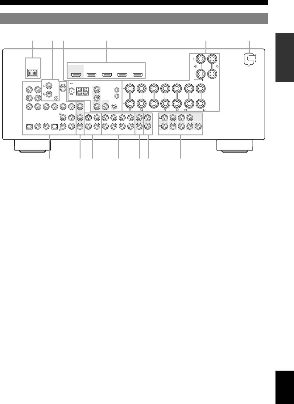
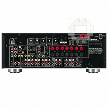
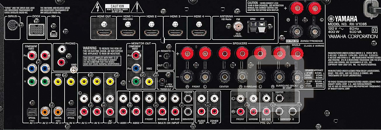
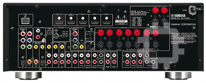
Part names and functions
Rear panel
INTRODUCTION
DOCK
HDMI OUT
HDMI 1
HDMI 2
HDMI 3
HDMI 4
(
BD/DVD
)
EXTRA SP
ZONE2/PRESENCE
PHONO ANTENNA
S VIDEO
MONITOR OUT
SPEAKERS
COMPONENT
SINGLE
VIDEO
UNBAL.
COMPONENT
FM
GND
AM
VIDEO
REMOTE
PR
PR
IN
PREPARATION
GND
OUT
PB
PB
VIDEO
VIDEO
Y
Y
0.1A MAX.
12V
FRONT
CENTER
SURROUND
SURROUND BACK/
TRIGGER OUT
BI-AMP
CENTER
SINGLE
CENTER
OPTICAL
COAXIAL
COAXIAL
OPTICAL
(
TV
)
(
CD
)
FRONT
SURROUND
SUR.BACK
SUBWOOFER
FRONT
SURROUND
SUR. BACK SUBWOOFER
12
AV
1
AV 2
AV 3
AV 4
AV 5
AV 6
OUT
AV
AUDIO1
AUDIO2
MULTI CH INPUT
AUDIO
OUT
ZONE2
OUT
PRE OUT
OPERATION
BASIC
a DOCK terminal
j MULTI CH INPUT jacks
For connecting an optional Yamaha iPod universal dock (YDS-
For connecting a player that supports a multi-channel output
11) or Bluetooth wireless audio receiver (YBA-10) (page 17).
(page 16).
b PHONO jacks
k AUDIO OUT jacks
OPERATION
ADVANCED
For connecting a turntable (page 15).
Outputs audio signals from a selected analog input source to an
external component (page 15).
c ANTENNA terminals
For connecting supplied FM and AM antennas (page 18).
l ZONE2 OUT jacks
Outputs sound of this unit to an external amplifier set in a
MONITOR OUT jacks
different zone (page 53).
Outputs visual signals from this unit to a video monitor, such as
a TV (page 14).
m PRE OUT jacks
Outputs multi-channel signals from up to 7.1 channels to an
REMOTE IN/OUT jacks
external amplifier (page 17).
For connecting an external component that supports the remote
INFORMATION APPENDIX
ADDITIONAL
control function (page 17).
TRIGGER OUT jack
For connecting an external terminal with a trigger input terminal
to operate it linked with operation of this unit. For example,
when an electric screen that supports a trigger input is
connected, it opens and closes linked with operation of an input
source selected in this unit.
d HDMI OUT/HDMI 1-4 jacks
For connecting an HDMI-compatible video monitor or external
components for HDMI inputs 1-4 (pages 14 and 15).
e SPEAKERS terminals
For connecting front, center, surround and surround back
speakers (page 11). Connect the presence speakers (page 11) or
the speakers for Zone2 (page 53) to EXTRA SP terminals.
f Power cable
Connect this cable to an AC wall outlet (page 19).
g AV 1-6 jacks
For connecting external components for audio/visual inputs 1-6
(page 15).
h AV OUT jacks
English
Outputs audio/visual signals from a selected analog input source
to an external component (page 15).
i AUDIO 1/2 jacks
For connecting external components for audio inputs 1-2
(page 15).
5 En
a
cd efb
ghijkl m
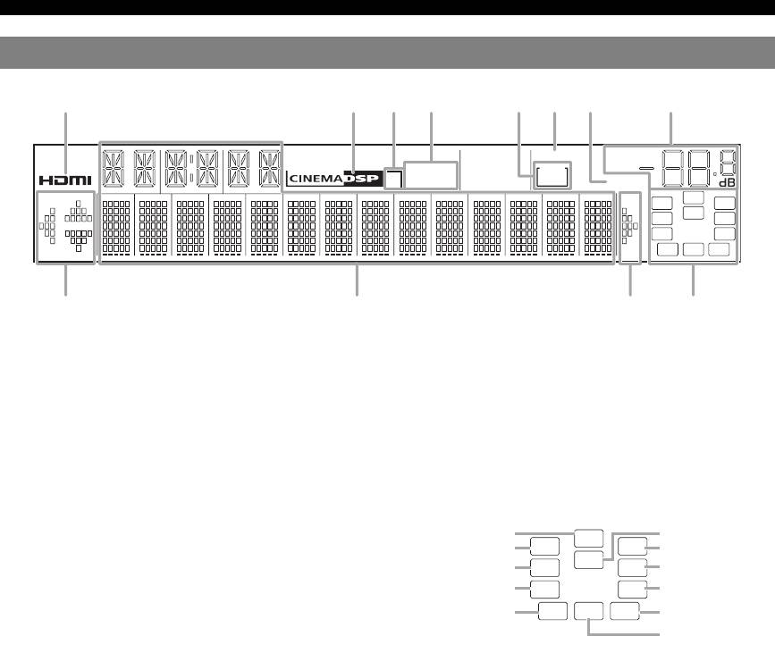
Part names and functions
Front panel display
SLEEP
VOL.
STEREO
ZONE
3
TUNED
2
MUTE
SW
PL PR
C
LR
SL SR
SBL SB SBR
a HDMI indicator
h VOLUME indicator
Lights up during normal communication when HDMI is
Displays volume levels.
selected as an input source.
i Cursor indicators
b CINEMA DSP indicator
Light up if corresponding cursors on the remote control are
Lights up when a sound field program that uses CINEMA DSP
available for operations.
is selected.
j Multi information display
c CINEMA DSP 3D indicator
Displays menu items and settings for the current operation.
Lights up when CINEMA DSP 3D is activated.
k Speaker indicators
d Tuner indicator
Indicate speaker terminals from which signals are currently
Lights up during receiving radio broadcast signals from an FM/
output.
AM station (page 30).
e ZONE2 indicator
Lights up when Zone2 is turned on.
f SLEEP indicator
Lights up when the sleep timer is activated (page 38).
g MUTE indicator
Flashes when audio is muted.
6 En
acbfhedg
ij ki
Subwoofer
Center
SW
Presence L Presence R
PL PR
C
Front L
LR
Front R
Surround L
SL SR
Surround R
Surround back L
SBL SB SBR
Surround back R
Surround back
Part names and functions
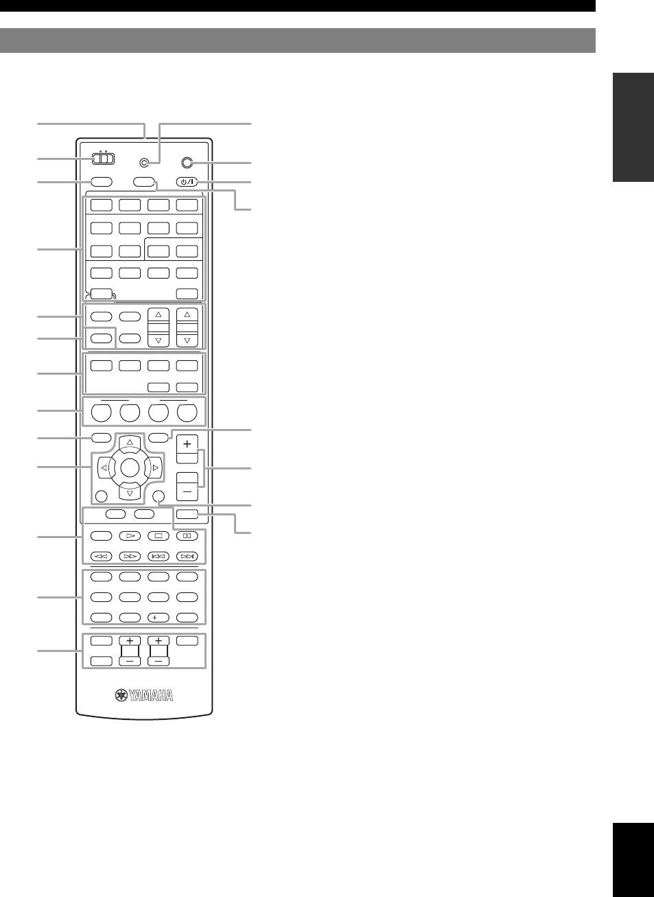
Remote control
d Input selection keys
INTRODUCTION
a
MAIN
ZONE2
TRANSMIT
CODE SET
b
o
POWER
POWER
c
SOURCE
SLEEP
p
HDMI
PREPARATION
1234
AV
1234
AUDIO
e Tuner keys
d
1256
V-AU X
PHONO
USB DOCK
TUNER
MULTI
e
FM
AM
f INFO
OPERATION
PRESET
TUNING
Changes the information shown on the front panel display
INFO
MEMORY
BASIC
(page 25).
ENHANCER SUR. DECODE
g Sound selection keys
MOVIE
MUSIC
STEREO
g
Selects sound field programs (page 26).
STRAIGHT
PURE DIRECT
h SCENE
SCENE
Switches between linked sets of input sources and sound field
BD
h
DVD
TV
CD
RADIO
programs (page 23).
OPTIONON SCREEN
r
i ON SCREEN
OPERATION
ADVANCED
i
Displays the GUI screen (page 24).
ENTER
VOLUME
s
RETURN
DISPLAY
t
TOP
MENU
MENU
MUTE
k External component operation keys
REC
u
k
Operate recording, playback etc. of external components
INFORMATION APPENDIX
ADDITIONAL
(page 55).
l Numeric keys
1234
Enter numbers.
l
7856
m TV control keys
Enables operations of a TV or a projector (page 55).
90
10
ENT
n TRANSMIT
TV
INPUT
POWER
Lights up when a signal is output from the remote control.
m
TV VOL
TV CH
o CODE SET
MUTE
Sets remote control codes for external component operations
(page 55).
p POWER
Switches this unit on and standby (page 19).
q SLEEP
Switches the sleep timer operations (page 38).
r OPTION
Displays the Option menu (page 39).
s VOLUME +/–
Adjust the volume of this unit (page 23).
a Remote control signal transmitter
t DISPLAY
Transmits infrared signals.
Displays the play information on the video monitor.
English
b MAIN/ZONE2
When an iPod is connected: Changes the operation mode of the
Switches amplifiers (Main or Zone2) to be operated by the
iPod connected to the Yamaha iPod universal dock (page 34).
remote control (page 54).
u MUTE
c SOURCE POWER
Turns the mute function on and off (page 24).
Switches an external component on and off.
7 En
n
HDMI 1-4
Selects HDMI inputs 1 through 4.
AV 1-6
Selects AV inputs 1 through 6.
AUDIO 1/2
Selects AUDIO inputs 1 and 2.
V-AUX
Selects a signal input from the VIDEO AUX jacks.
PHONO
Selects a signal input from the PHONO jacks.
USB
Selects a USB device connected to the USB port.
DOCK
Selects a Yamaha iPod universal dock/Bluetooth
wireless audio receiver connected to the DOCK
terminal.
TUNER
Selects the FM/AM tuner.
q
MULTI
Selects a signal input from the MULTI CH
INPUT jacks.
FM/AM
Switches a band between FM and AM.
MEMORY
Presets radio stations.
PRESET k / n
Selects a preset station.
TUNING k / n
Changes FM/AM frequencies.
f
j Cursors k / n / l / h
Select menu items or change
j
settings.
ENTER
Confirms a selected item.
RETURN
Returns to the previous screen or
ends the menu display.
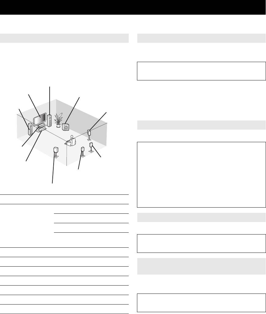
Quick start guide
When you use this product for the first time, perform setup following the steps below. See the related pages for details on
operations and settings.
Step 1: Prepare items for setup
Step 2: Set up your speakers
Prepare speakers, DVD player, cables, and other items
Place your speakers in the room and connect them to this
necessary for setup.
unit.
For example, prepare the following items for setting up a
• Placing speakers ☞P. 1 0
7.1-channel sound system.
• Connecting speakers ☞P. 1 1
Front right speaker
y
Video monitor
• This unit has a YPAO (Yamaha Parametric Room Acoustic Optimizer)
Subwoofer
that automatically optimizes this unit based on room acoustic
Front left
characteristics (audio characteristics of the speakers, speaker positions,
speaker
and room acoustics, etc.).
Surround right speaker
You can enjoy good balanced sound without special knowledge by using
the YPAO technology (☞P. 20).
Step 3: Connect your components
Connect your TV, DVD player, or other components.
Center
• Connecting a TV monitor or projector ☞P. 1 4
speaker
• Connecting other components ☞P. 1 5
Surround Back
• Connecting a multi-format player or an
Components
right speaker
external decoder ☞P. 1 6
(such as DVD player)
Surround Back
• Connecting an external amplifier ☞P. 1 7
left speaker
• Connecting a USB storage device ☞P. 1 8
Surround left speaker
• Connecting a Yamaha iPod universal dock or
Bluetooth wireless audio receiver ☞P. 1 7
Requirements qty.
• Connecting the FM and AM antennas ☞P. 1 8
Speakers Front speaker 2
Center speaker 1
Step 4: Turn on the power
Surround speaker 2
Connect the power cable and turn on this unit.
Surround back
2
• Connecting the power cable ☞P. 1 9
speaker
• Turning this unit on and off ☞P. 1 9
Active subwoofer 1
Speaker cable 7
Step 5: Select the input source and start
Subwoofer cable 1
playback
Reproduction component such as DVD player 1
Select the component connected in step 3 as an input
source and start playback.
Video monitor such as TV 1
Video cable or HDMI cable 2
• Basic procedure ☞P. 2 3
• Selecting sound field programs ☞P. 2 6
Audio cable 2
y
y
• This unit supports the SCENE function (page 23) that changes the input
• Prepare two magnetically shielded speakers (for front). The priority of
source and sound field program at one time. Four scenes are preset for
the requirement of other speakers is as follows:
different purposes for Blu-ray disc, DVD and CD, and you can select
1 Two surround speakers
from a scene from those just by pressing a remote control key.
2 One center speaker
3 One (or two) surround back speaker(s)
• If your video monitor is a CRT, we recommend that you use magnetically
shielded speakers.
• Video and audio cables are unnecessary if you use HDMI cables.
8 En


