Zanussi ZBB 7297: TECHNICAL INFORMATION
TECHNICAL INFORMATION: Zanussi ZBB 7297
TECHNICAL INFORMATION
Fridge Net Capacity lt.
210
Freezer Net Capacity lt.
70
Energy Consumption kWh/24h
0,871
Energy Consumption kWh/annuo
318
Freezing Capacity kg/24h
4
Rising Time
24
The Technical info are on the rating plate situated on the left inside the appliance.
INSTALLATION
Location
Attention
The appliance should be installed well away from
sources of heat such as radiators, boilers, direct
It must be possible to disconnect the appliance from
sunlight etc.
the mains power supply; the plug must therefore be
easily accessible after installation.
For building into kitchen units follow the special “
Building-in” instructions given.
Electrical connection
Before plugging in, ensure that the voltage and
frequency shown on the serial number plate
correspond to your domestic power supply. Voltage
can vary by ±6% of the rated voltage.
For operation with different voltages, a suitably sized
auto-transformer must be used.
The appliance must be earthed.
The power supply cable plug is provided with a
contact for this purpose.
If the domestic power supply socket is not earthed,
connect the appliance to a separate earth in
compliance with current regulations, consulting a
specialist technician.
The Manufacturer declines all responsibility if
the above safety precautions are not observed.
This appliance complies with the following
E.E.C. Directives:
- 87/308 EEC of 2/6/87 relative to radio interference
suppression.
- 73/23 EEC of 19.2.73 (Low Voltage Directive) and
subsequent modifications;
- 89/336 EEC of 3.5.89 (Electromagnetic
Compatibility Directive) and subsequent
modifications.
24
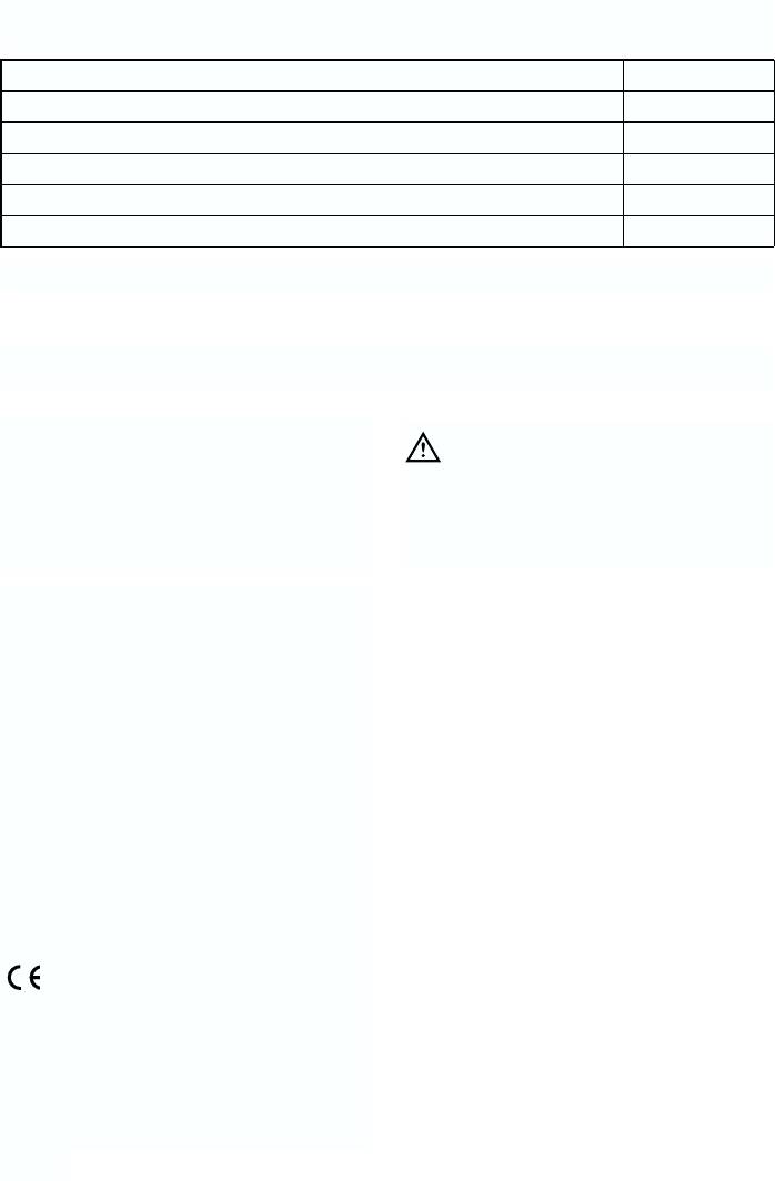
Instructions for totally built-in appliances
Door reversibility
The appliance is supplied with the right
or left door opening. To change the opening
direction of the door proceed as in the
following instructions before installing it.
1. Unscrew the upper pin and remove the spacer.
2. Remove the upper pin and the upper door.
3. Unscrew the middle hinge.
4. Remove the lower door.
5. Unscrew the lower pin and refit it on the opposite side
6. Refit the lower door.
7. Rescrew the middle hinge und the covers on the
opposite side.
8. Refit the upper door and rescrew the hinge pin and
the spacer on the opposite side.
Instructions for totally built-in
50 mm
min.
2
appliances
200 cm
Dimensions of the recess
Height (1) 1780 mm
Depth (2) 550 mm
min.
2
200 cm
Width (3) 560 mm
For safety reasons, minimum ventilation must be as
shown in Fig. Attention: keep ventilation openings
D567
clear of obstruction.
5
0
540
Furthermore, it is necessary that the niche is provid
with a conduct of ventilation having the following
3
dimensions:
depth 50 mm
width 540 mm
2
1
PR01
25
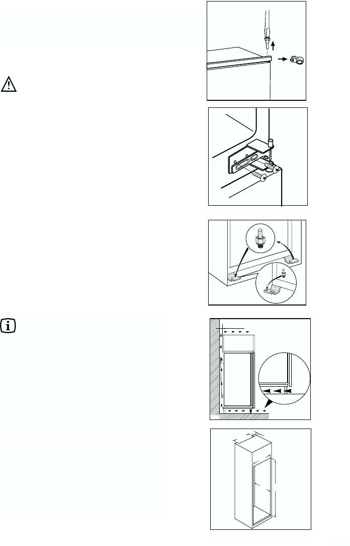
Make sure that a distance of 44 mm is maintained in
the lower part between the kitchen furniture and the
border of the appliance.
The lower hinge cover inserted in the accessories
1
bag, is useful to guarantee the exact position of the
kitchen furniture and the appliance.
Also make sure that the appliance does not clamp
44mm
the mains cable
2
Fasten the appliance with 4 screws provided in the
kit included with the appliance.
(I = short) (P = long)
I
P
Apply the sealing strip pushing it between the
refrigerator and the adjacent cabinet.
D724
From the plastic cover (E), which is used to cover the
hinge with the pivot pin, you must take away the part
as indicated in the drawing.
This operation is made easer since there is, in the
internal part of the cover hinge lid a groove that
facilates the removal of this coomponent.
“Remove the part marked with DX, if the pivot pin is
inserted in the right hinge, SX in opposite case.”
Apply covers (C-D) on joint cover lugs and into hinge
holes.
Snap vent grille (B) and hinge covers (E) into
position.
C
D
E
E
B
26
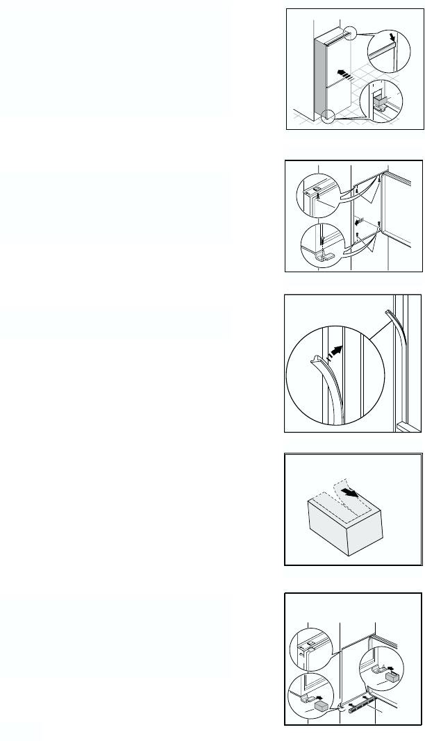
Separate parts Ha, Hb, Hc, Hd as shown in the
figure.
Ha
Hb
Hc
Hd
PR266
Place guide (Ha) on the inside part of the furniture
ca. 50 mm
door, up and down as shown in the figure and mark
90°
the position of external holes. After having drilled
holes, fix the guide with the screws supplied.
2
1
m
m
90°
ca. 50 mm
2
1
m
m
Fix cover (Hc) on guide (Ha) until it clips into place
Ha
Hc
PR33
8mm
Open the appliance door and the furniture door at
90°. Insert the small square (Hb) into guide (Ha).
Put together the appliance door and the furniture
door and mark the holes as indicated in the figure. .
Ha
Hb
PR167
Remove the brackets and mark a distance of 8 mm
8mm
from the outer edge of the door where the nail must
be fitted (K).
K
Ha
27
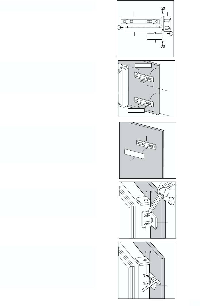
Place the small square on the guide again and fix it
with the screws supplied.
Should the lining up of the furniture door be
necessary, use the clearance of slots.
At the end of operations, it is necessary to check if
the door of the furniture closes properly.
Hb
PR168
Fix cover (Hd) on guide (Hb) until it clips into place.
Hb
Hd
PR167/1
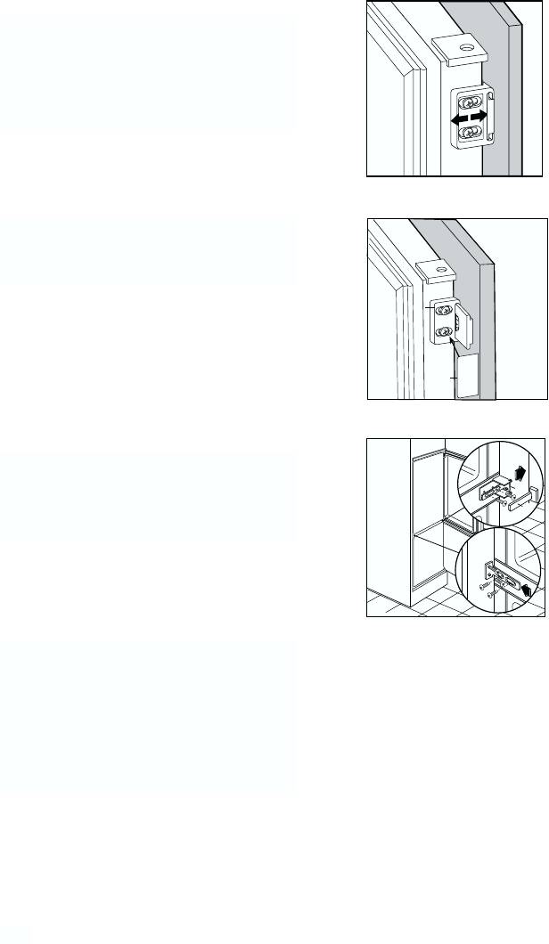
If the appliance is to be fitted laterally to the kitchen
unit, it will be sufficient to loosen the screws of the
little plates (D), move them as shown in Fig. and
D
then fasten them up again. Fit the cover (E).
E
D734
After having reversed the opening direction of
the doors check that all the screws are properly
tightened and that the magnetic seal adheres to
the cabinet. If the ambient temperature is cold
(i.e. in Winter), the gasket may not fit perfectly to
the cabinet. In that case, wait for the natural
fitting of the gasket or accelerate this process by
heating up the part involved with a normal
hairdrier.
28


www.electrolux.com
www.zanussi.ru


