Asus V2-PH1: Internal components Selecting the voltage
Internal components Selecting the voltage: Asus V2-PH1
Table of contents
- Front panel features Rear panel features
- Internal components Selecting the voltage
- Removing the side cover and front panel assembly Installing a CPU
- To install a CPU:
- English
- Installing the CPU fan and heatsink assembly
- Installing a DIMM Installing an expansion card
- Installing storage drives
- Removing the bay covers and reinstalling the front panel assembly and side cover
Internal components
55
55
5
22
22
2
English
PS/2KBMS
CPU_FAN
T: Mouse
B: Keyboard
33
33
3
COM1
ATX12V
I/O
LGA775
Super
PWR_FAN
11
11
1
66
66
6
FLOPPY
PARALLEL PORT
44
44
¤
4
VGA
Bottom:
Top:
COM2
99
99
9
USB1
88
88
8
77
77
USB2
1394
7
LAN_USB34
Intel
¤
GMCH
DDR DIMM_A1 (64 bit,240-pin module)
DDR DIMM_A2 (64 bit,240-pin module)
DDR DIMM_B1 (64 bit,240-pin module)
DDR DIMM_B2 (64 bit,240-pin module)
AUDIO
945G
EATXPWR
CHA_FAN
PCIEX16
PRI_IDE
1010
1010
10
82573L
Intel
PCI1
SB_PWR
Intel
¤
Intel FWH
4Mb
11
11
1
11
11
1
ICH7
PLED
CHASSIS
SPEAKER
11
11
1
33
33
3
PCI2
CD
SATA4SATA 3
CR2032 3V
ALC882
PCIEX1_1
TSB43AB22A
TI
Lithium Cell
SATA 1 SATA 2
11
11
1
22
22
CMOS Power
2
CLRTC
BUZZ
F_PANEL
AAFP
SPDIF_OUT
IE1394_2
USB56
USB78
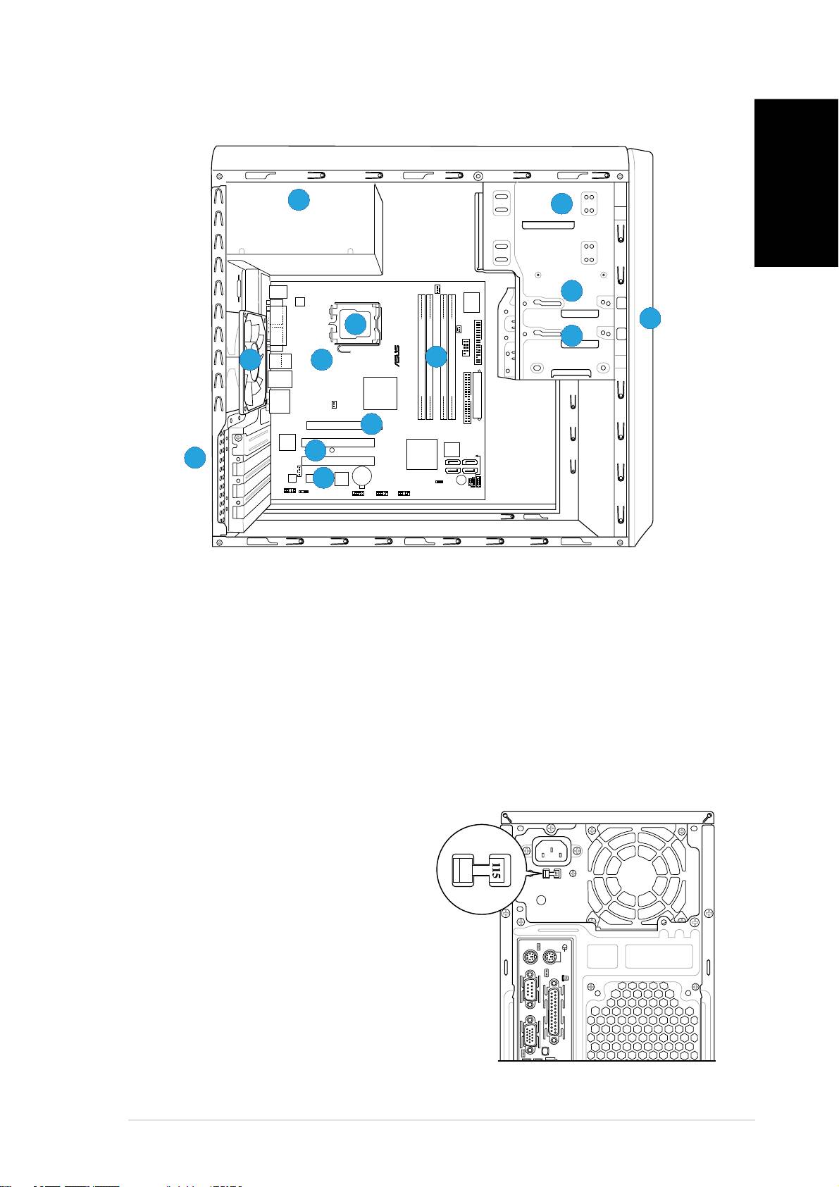
1. Front panel cover
8. ASUS motherboard
2. 5.25-inch optical drive bays
9. Chassis fan
3. Hard disk drive bay
10. PCI Express x16 slot
4. Floppy disk drive bay
11. PCI slots
5. Power supply unit
12. PCI Express x1 slot
6. CPU socket
13. Metal bracket lock
7. DIMM sockets
Selecting the voltage
The system’s power supply unit has a
115 V/230 V voltage selector switch
located beside the power connector.
Use this switch to select the
appropriate system input voltage
according to the voltage supply in your
area.
If the voltage supply in your area is
100-127 V, set the switch to 115 V.
If the voltage supply in your area is
200-240 V, set the switch to 230 V.
Quick installation guideQuick installation guide
Quick installation guideQuick installation guide
Quick installation guide
33
33
3
