Asus Pundit-PH3: instruction
Class: Household, kitchen appliances, electronics and equipment
Type: Computer
Manual for Asus Pundit-PH3
Table of contents
- Front panel features Rear panel features
- Internal components Selecting the voltage
- Removing the cover Removing the front panel assembly
- Installing a CPU Installing the CPU
- Reinstalling the CPU fan and heatsink assembly Installing a DIMM
- Installing an expansion card Installing an optical drive Installing a SATA hard disk drive
- Replacing the covers
English
Pundit-PH3
Pundit-PE3
Barebone Systems
Quick Start Guide
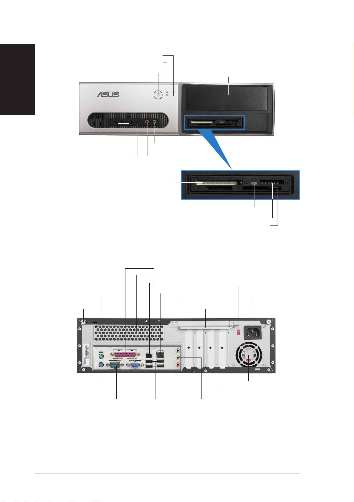
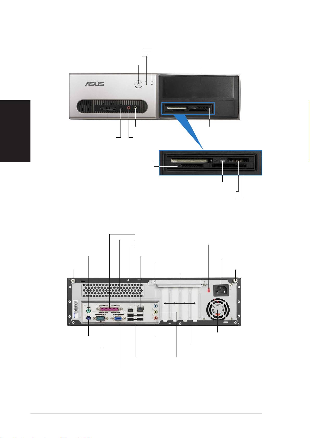
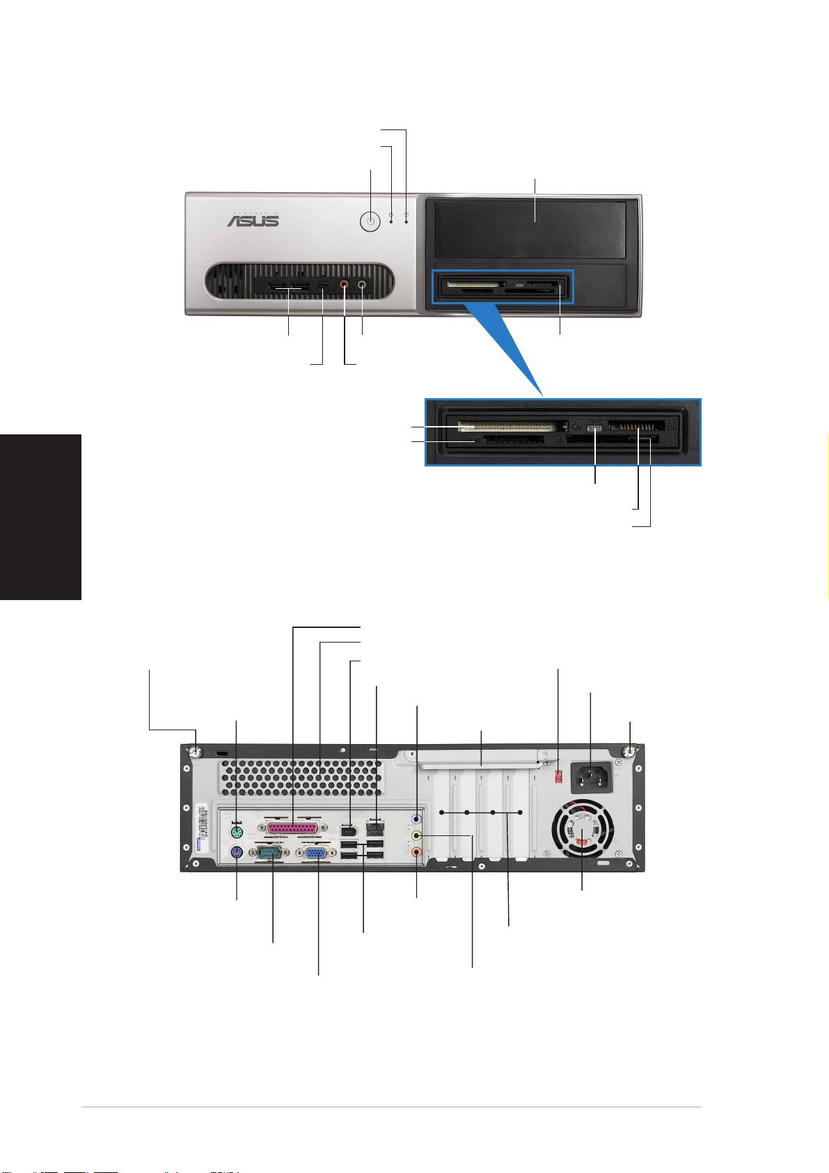
Front panel features
HDD LEDHDD LED
HDD LEDHDD LED
HDD LED
English
Power LEDPower LED
Power LEDPower LED
Power LED
Power buttonPower button
Power buttonPower button
Power button
5.25-inch drive bay cover5.25-inch drive bay cover
5.25-inch drive bay cover5.25-inch drive bay cover
5.25-inch drive bay cover
USB 2.0 portsUSB 2.0 ports
USB 2.0 portsUSB 2.0 ports
USB 2.0 ports
Microphone portMicrophone port
Microphone portMicrophone port
Microphone port
6-in-1 card reader*6-in-1 card reader*
6-in-1 card reader*6-in-1 card reader*
6-in-1 card reader*
4-pin IEEE 1394a port
4-pin IEEE 1394a port4-pin IEEE 1394a port
4-pin IEEE 1394a port4-pin IEEE 1394a port
Headphone portHeadphone port
Headphone portHeadphone port
Headphone port
®®
®®
®
CompactFlashCompactFlash
CompactFlashCompactFlash
CompactFlash
card slot card slot
card slot card slot
card slot
Secure Digital™/MultimediaCard slotSecure Digital™/MultimediaCard slot
Secure Digital™/MultimediaCard slotSecure Digital™/MultimediaCard slot
Secure Digital™/MultimediaCard slot
*Pundit-PH3 model only
Card reader LEDCard reader LED
Card reader LEDCard reader LED
Card reader LED
®®
®®
®
Memory StickMemory Stick
Memory StickMemory Stick
Memory Stick
/Pro™ card slot/Pro™ card slot
/Pro™ card slot/Pro™ card slot
/Pro™ card slot
®®
®®
®
SmartMediaSmartMedia
SmartMediaSmartMedia
SmartMedia
card slot card slot
card slot card slot
card slot
Rear panel features
Parallel portParallel port
Parallel portParallel port
Parallel port
Air ventsAir vents
Air ventsAir vents
Air vents
IEEE 1394a portIEEE 1394a port
IEEE 1394a portIEEE 1394a port
IEEE 1394a port
Voltage selectorVoltage selector
Voltage selectorVoltage selector
Voltage selector
PS/2 mouse portPS/2 mouse port
PS/2 mouse portPS/2 mouse port
PS/2 mouse port
LAN (RJ-45) portLAN (RJ-45) port
LAN (RJ-45) portLAN (RJ-45) port
LAN (RJ-45) port
Power connectorPower connector
Power connectorPower connector
Power connector
Line In portLine In port
Line In portLine In port
Line In port
Cover screwCover screw
Cover screwCover screw
Cover screw
Metal bracket lockMetal bracket lock
Metal bracket lockMetal bracket lock
Metal bracket lock
Cover screwCover screw
Cover screwCover screw
Cover screw
Power fan ventsPower fan vents
Power fan ventsPower fan vents
Power fan vents
Line OutLine Out
Line OutLine Out
Line Out
PS/2 keyboard portPS/2 keyboard port
PS/2 keyboard portPS/2 keyboard port
PS/2 keyboard port
portport
port
PCI slot metal bracketsPCI slot metal brackets
PCI slot metal bracketsPCI slot metal brackets
PCI slot metal brackets
portport
Serial portSerial port
Serial portSerial port
Serial port
USB 2.0 portsUSB 2.0 ports
USB 2.0 portsUSB 2.0 ports
USB 2.0 ports
Microphone portMicrophone port
Microphone portMicrophone port
Microphone port
VGA portVGA port
VGA portVGA port
VGA port
22
22
2
Quick Installation GuideQuick Installation Guide
Quick Installation GuideQuick Installation Guide
Quick Installation Guide
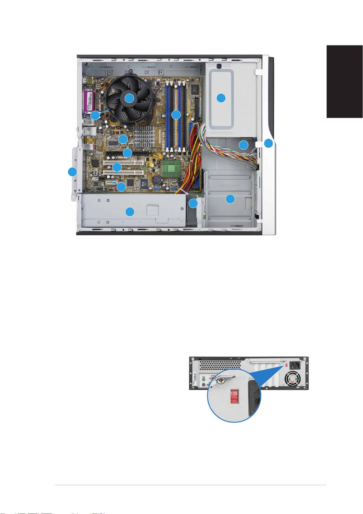
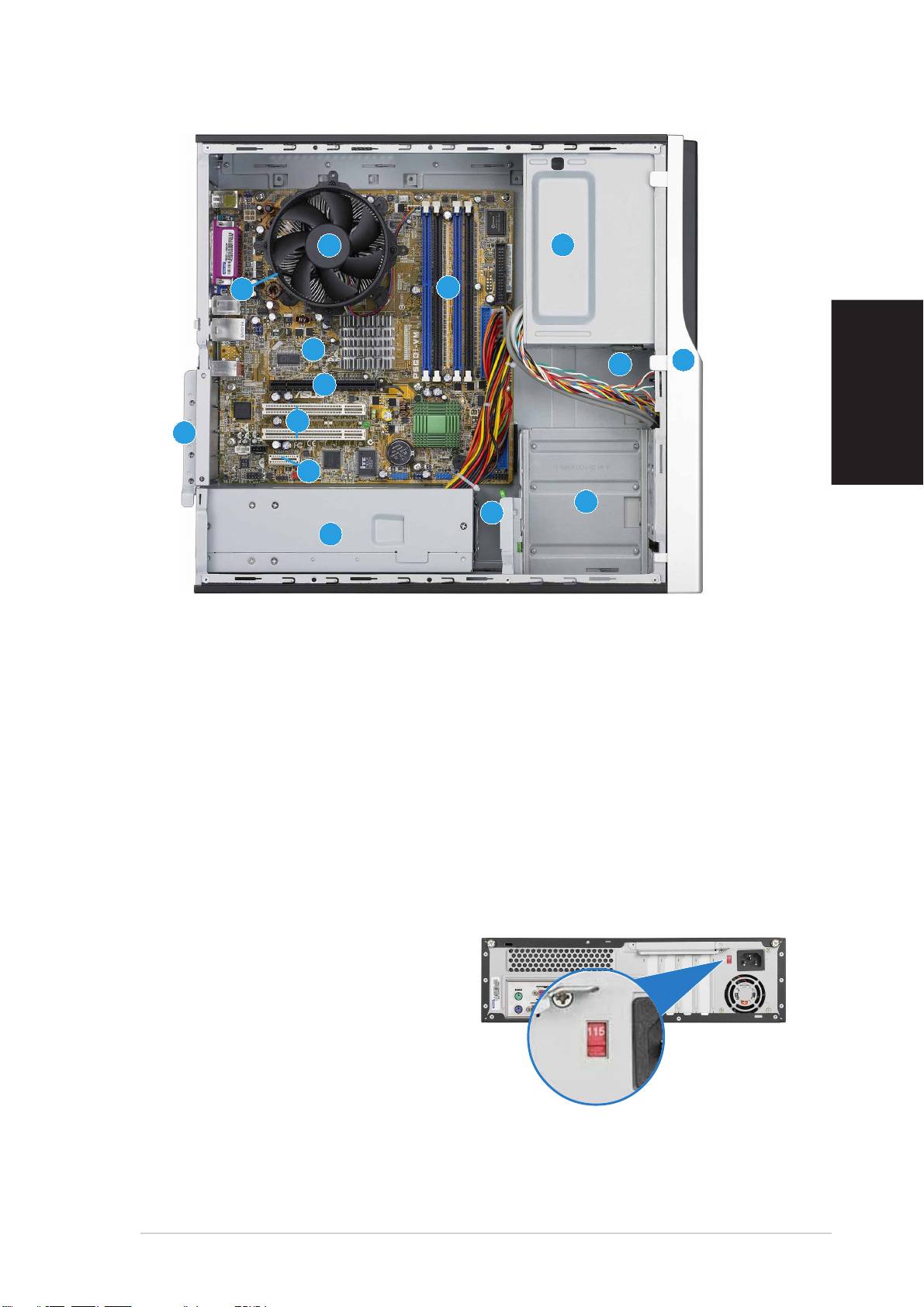
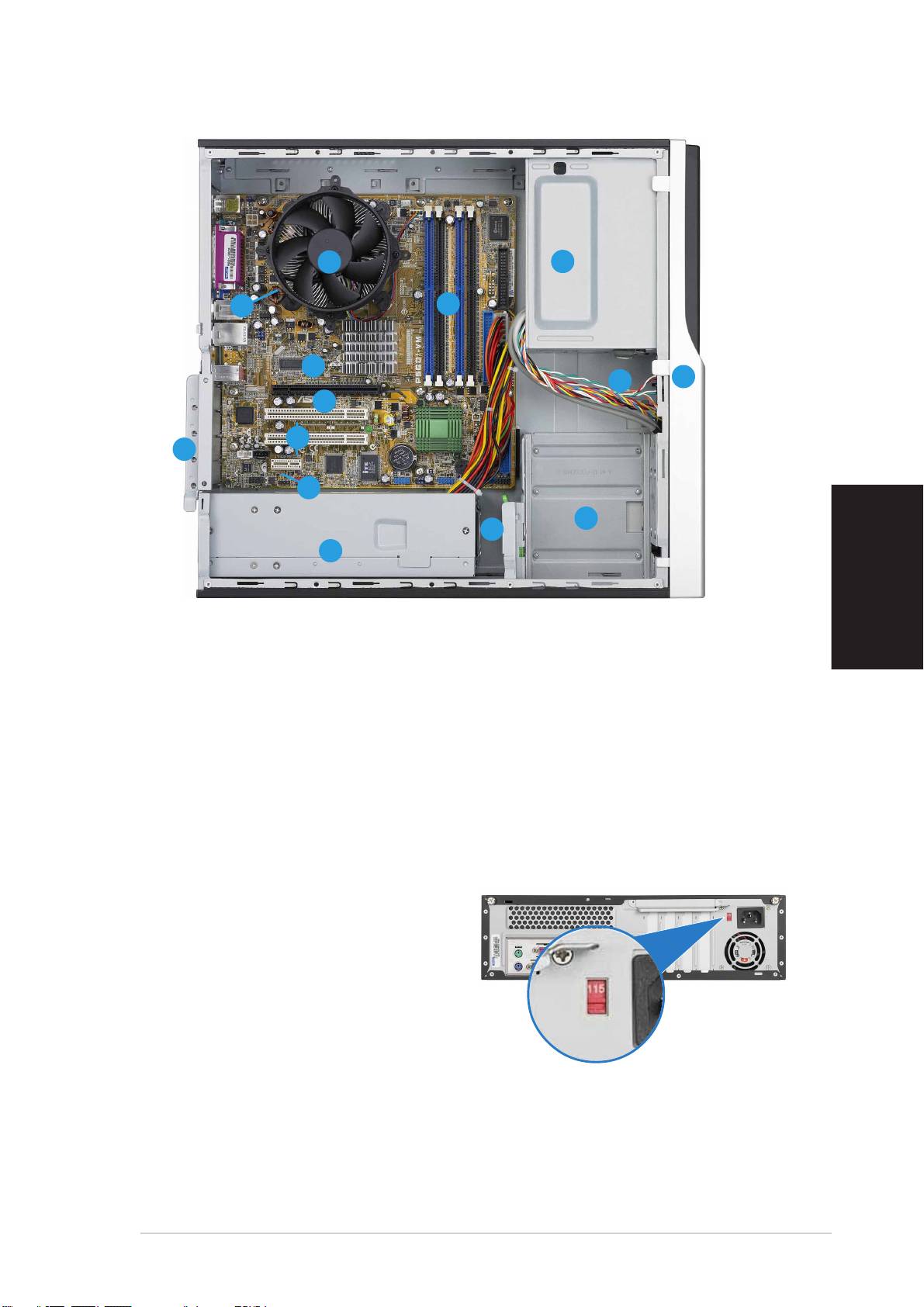
Internal components
English
11
11
1
33
33
3
11
11
1
11
11
1
22
22
2
1414
1414
14
1010
1010
10
2
3
22
22
33
33
99
99
9
88
88
8
11
11
1
11
11
1
77
77
7
44
44
4
55
55
5
66
66
6
1. 5.25-inch empty optical drive bay
9. PCI Express x16 slot
2. Front panel cover
(on Pundit-PH3 model only)
3. Optical drive lock
10. ASUS motherboard
4. Hard disk drive bays
11. Metal bracket lock
5. Hard disk drive lock
12. LGA775 socket
(under the CPU
fan and heatsink assembly)
6. Power supply unit
13. CPU fan and heatsink assembly
7. PCI Express x1 slot
14. DIMM sockets
8. PCI slots
Selecting the voltage
The system’s power supply unit has
a 115 V/230 V voltage selector
switch located beside the power
connector. Use this switch to select
the appropriate system input voltage
according to the voltage supply in
your area.
If the voltage supply in your area is
100-127 V, set the switch to 115 V.
If the voltage supply in your area is
200-240 V, set the switch to 230 V.
Quick Installation GuideQuick Installation Guide
Quick Installation GuideQuick Installation Guide
Quick Installation Guide
33
33
3
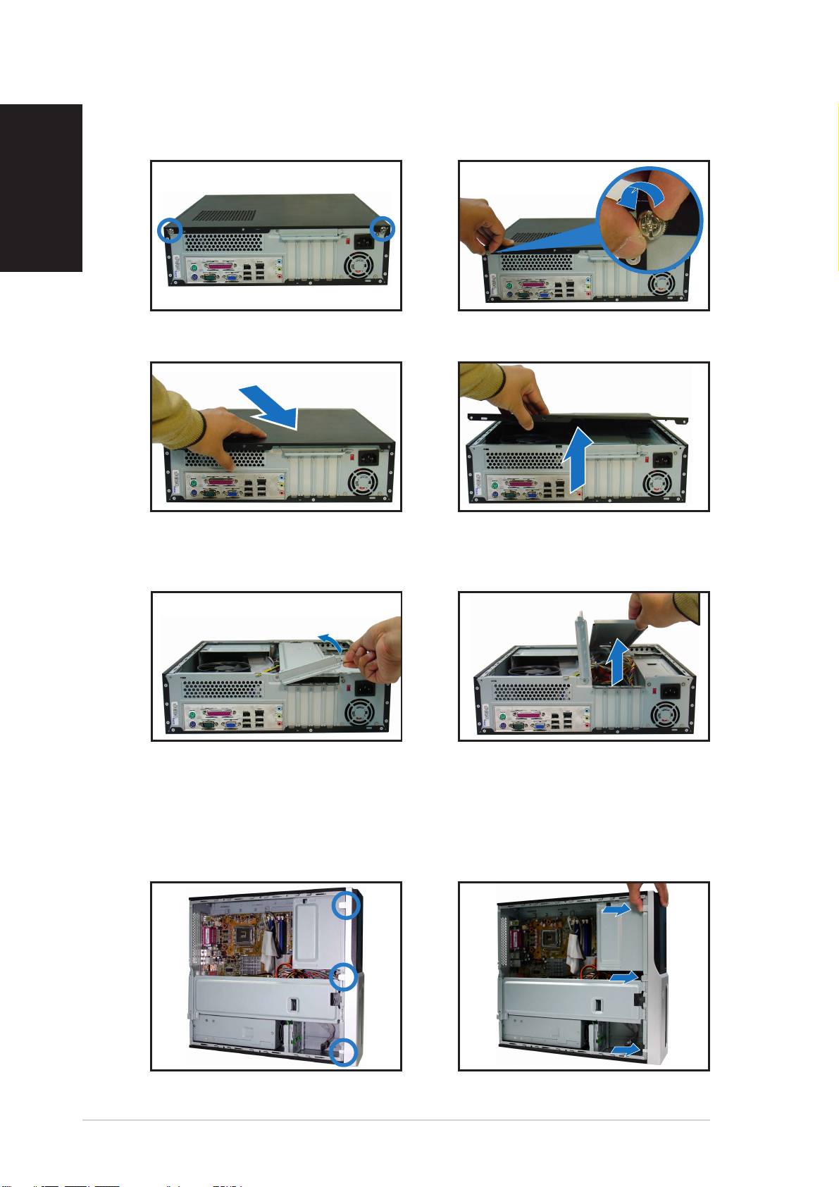
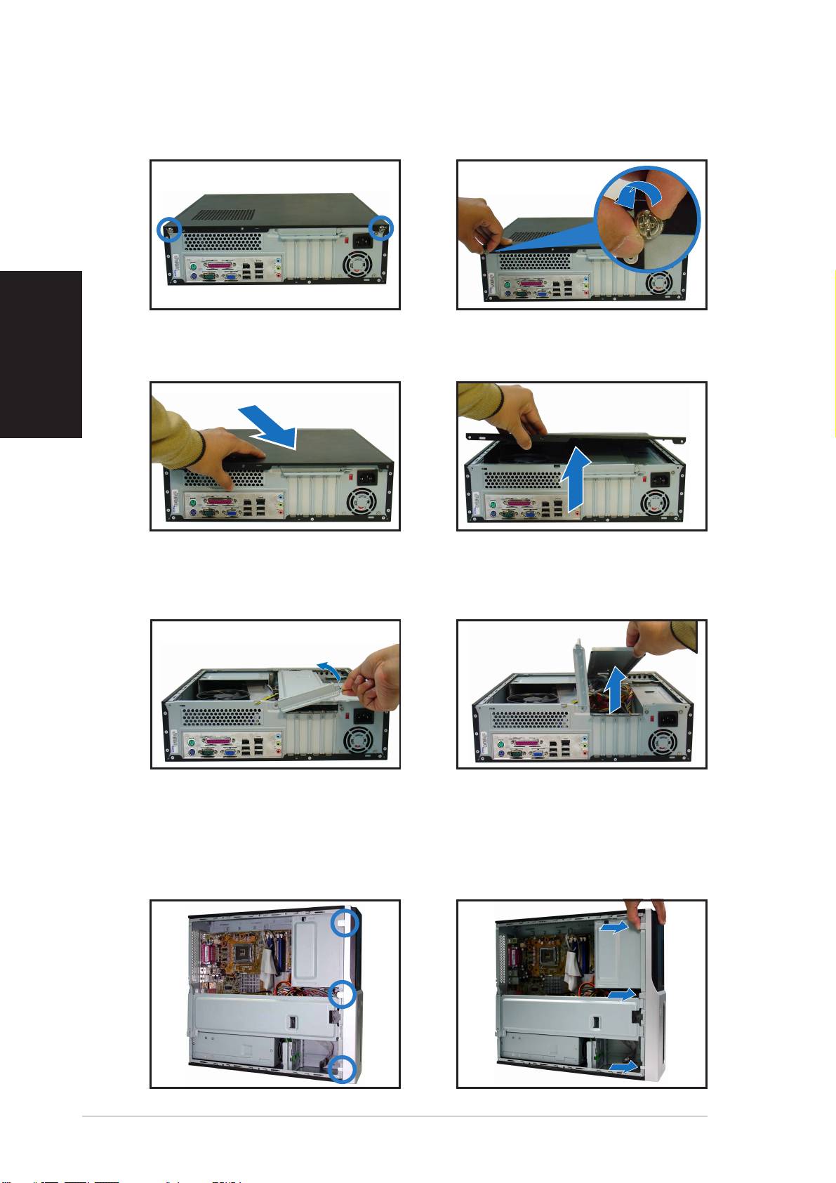
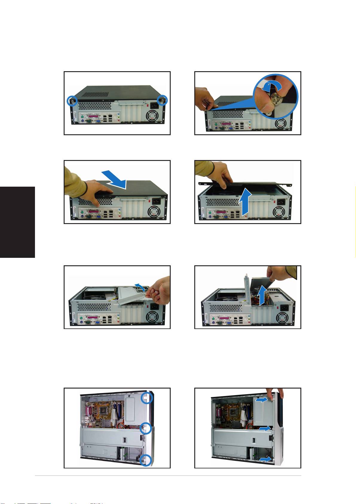
Removing the cover
1. Locate two cover screws.
2. Remove the cover screws.
English
3. Pull the cover.
4. Lift the cover, then set aside.
5. Lift the expansion card lock to
6. Lift the chassis support
a 90º-100º angle.
bracket, then remove.
Removing the front panel assembly
1. Locate the front panel
2. Pull the hooks outward to
assembly hooks.
remove.
44
44
4
Quick Installation GuideQuick Installation Guide
Quick Installation GuideQuick Installation Guide
Quick Installation Guide
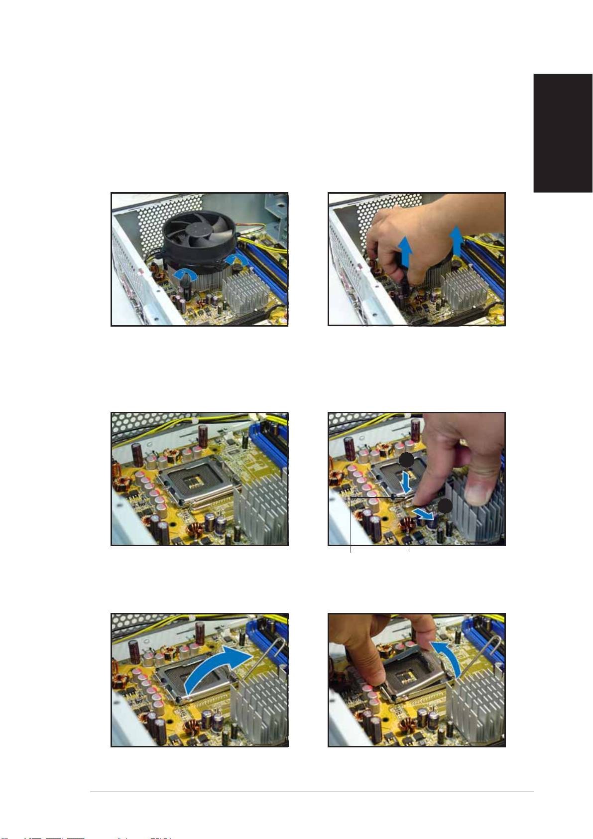
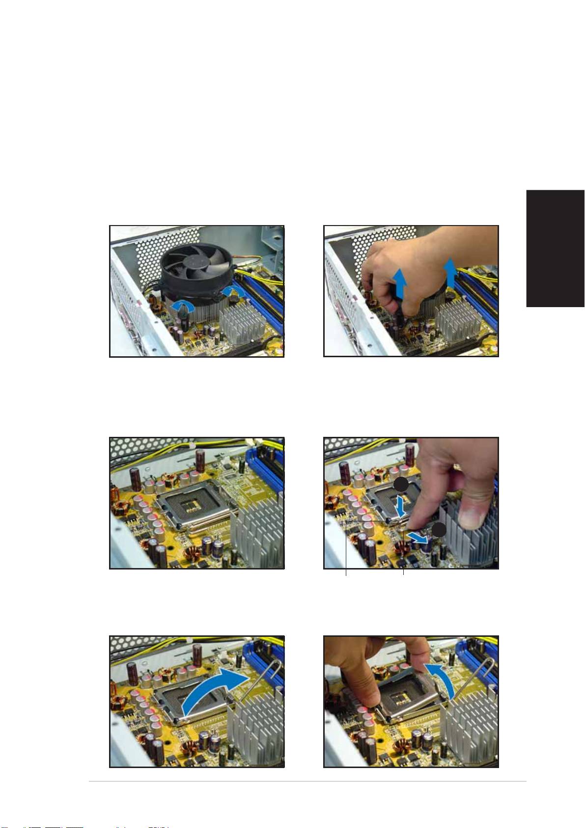
Installing a CPU
Removing the CPU fan and heatsink assemblyRemoving the CPU fan and heatsink assembly
Removing the CPU fan and heatsink assemblyRemoving the CPU fan and heatsink assembly
Removing the CPU fan and heatsink assembly
1. Disconnect the CPU fan cable.
3. Pull two fasteners at a time to
remove the fan and heatsink.
2. Rotate the fasteners
English
counterclockwise.
4. After removing the fan, rotate
each fastener clockwise.
Installing the CPUInstalling the CPU
Installing the CPUInstalling the CPU
Installing the CPU
1. Locate the CPU socket.
2. Unlock the load lever.
AA
AA
A
BB
BB
B
Retention tabRetention tab
Retention tabRetention tab
Retention tab
Load leverLoad lever
Load leverLoad lever
Load lever
3. Lift the load lever. 4. Lift the load plate.
Quick Installation GuideQuick Installation Guide
Quick Installation GuideQuick Installation Guide
Quick Installation Guide
55
55
5
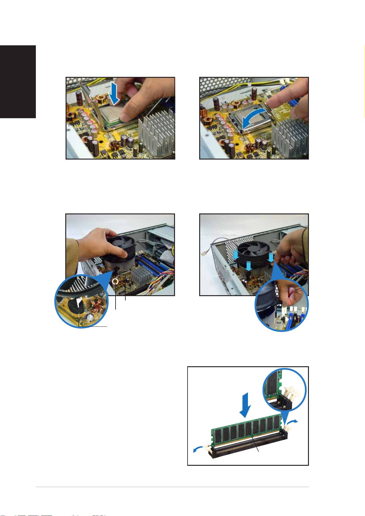
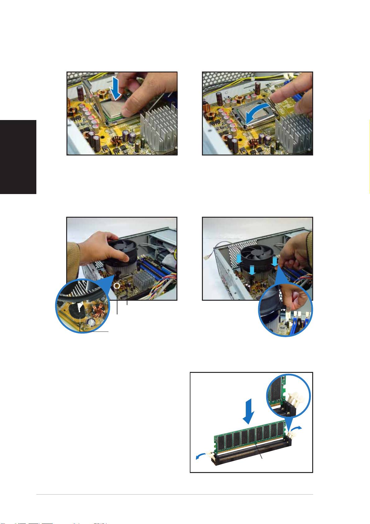
5. Install the CPU.
6. Close the load plate, then lock
English
the load lever.
Reinstalling the CPU fan and heatsink assemblyReinstalling the CPU fan and heatsink assembly
Reinstalling the CPU fan and heatsink assemblyReinstalling the CPU fan and heatsink assembly
Reinstalling the CPU fan and heatsink assembly
1. Place the heatsink on top of
2. Push down the fasteners.
the installed CPU.
3. Connect the CPU fan cable.
FastenerFastener
FastenerFastener
Fastener
Motherboard holeMotherboard hole
Motherboard holeMotherboard hole
Motherboard hole
Narrow end of the grooveNarrow end of the groove
Narrow end of the grooveNarrow end of the groove
Narrow end of the groove
Installing a DIMM
1. Locate the DIMM sockets in the
UnlockedUnlocked
UnlockedUnlocked
Unlocked
motherboard.
retaining clipretaining clip
retaining clipretaining clip
retaining clip
2. Unlock a DIMM socket by
pressing the retaining clips
outward.
3. Align a DIMM on the socket such
that the notch on the DIMM
matches the break on the
socket.
DDR DIMM notchDDR DIMM notch
DDR DIMM notchDDR DIMM notch
DDR DIMM notch
66
66
6
Quick Installation GuideQuick Installation Guide
Quick Installation GuideQuick Installation Guide
Quick Installation Guide
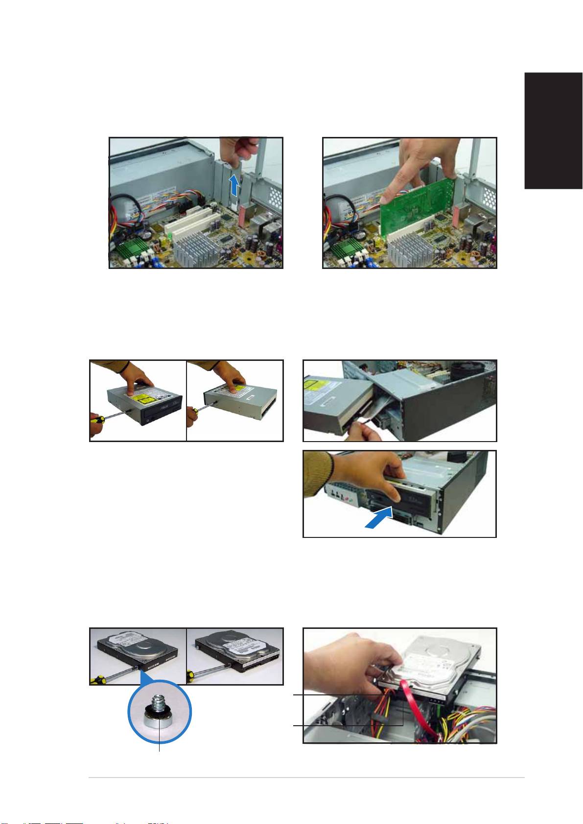
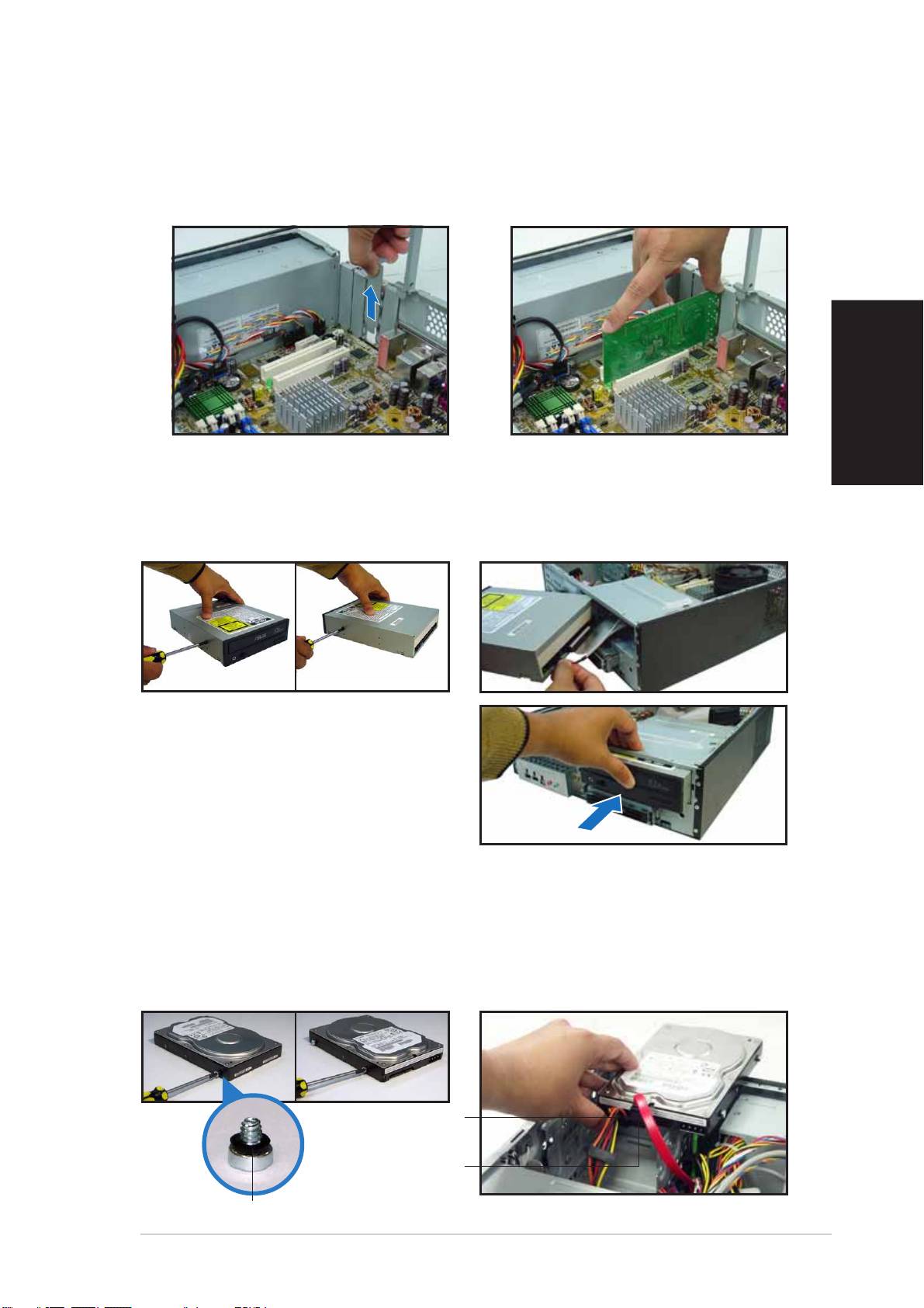
Installing an expansion card
1. Remove the metal cover
2. Insert the card connector to
opposite the slot that you
the slot, then press the card
intend to use.
firmly until it fits in place.
English
Installing an optical drive
1. Drive a screw on the top right
2. Connect the IDE and audio
screw hole on both sides of
cable at the back of the drive.
the drive.
3. Push the drive all the way into
the bay until the drive lock clicks.
4. Connect a 4-pin power plug
from the power supply unit to
the power connector at the
back of the drive.
Installing a SATA hard disk drive
1. Drive two screws with rubber
2. Connect the SATA signal and
washers on both sides of the
power plug at the back of the
drive.
drive.
Power cablePower cable
Power cablePower cable
Power cable
and plugand plug
and plugand plug
and plug
Signal cableSignal cable
Signal cableSignal cable
Signal cable
and plugand plug
and plugand plug
and plug
Rubber washerRubber washer
Rubber washerRubber washer
Rubber washer
Quick Installation GuideQuick Installation Guide
Quick Installation GuideQuick Installation Guide
Quick Installation Guide
77
77
7
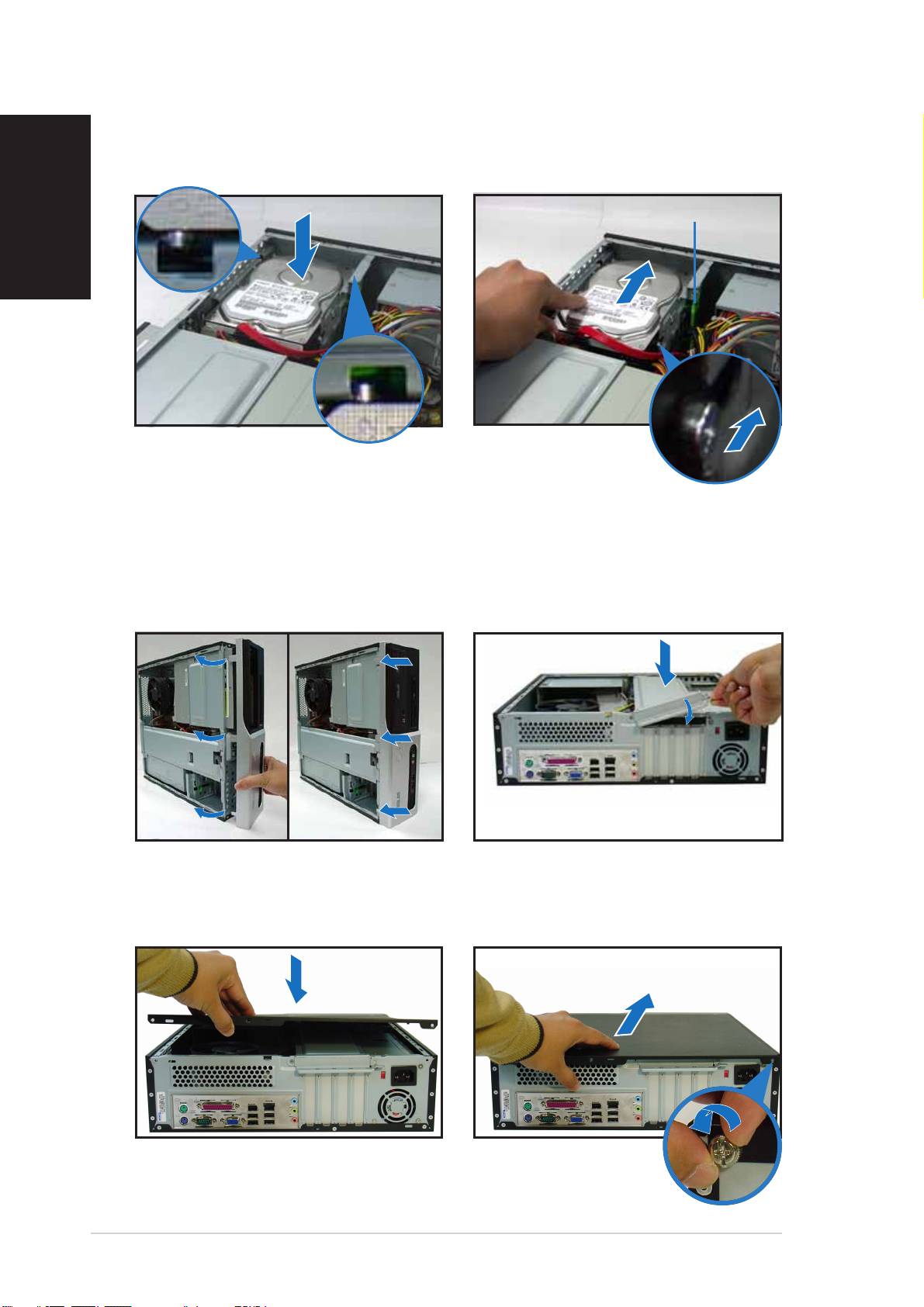
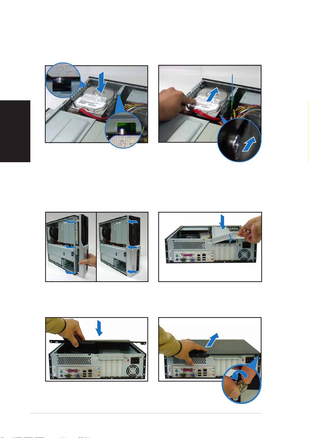
3. Place the HDD on the tray. 4. When the HDD screws align,
English
push the drive on the bay.
HDD screw lockHDD screw lock
HDD screw lockHDD screw lock
HDD screw lock
Replacing the covers
1. Replace the front panel
2. Reinstall the metal chassis
assembly. Remove the 5.25”
support and the expansion
drive bay cover when you
card lock.
installed an optical drive.
3. Insert the cover hooks to the
4. Push the cover to the direction
holes on the chassis side.
of the front panel, then
replace the cover screws.
88
88
8
Quick Installation GuideQuick Installation Guide
Quick Installation GuideQuick Installation Guide
Quick Installation Guide
Pundit-PH3
Pundit-PE3
Système barebone
Français
Guide de démarrage rapide
Caractéristiques de la façade
LED HDDLED HDD
LED HDDLED HDD
LED HDD
LED d’alimentationLED d’alimentation
LED d’alimentationLED d’alimentation
LED d’alimentation
Bouton d’alimentationBouton d’alimentation
Bouton d’alimentationBouton d’alimentation
Bouton d’alimentation
Cache de baie 5.25 poucesCache de baie 5.25 pouces
Cache de baie 5.25 poucesCache de baie 5.25 pouces
Cache de baie 5.25 pouces
Français
Ports USB 2.0Ports USB 2.0
Ports USB 2.0Ports USB 2.0
Ports USB 2.0
Port MicrophonePort Microphone
Port MicrophonePort Microphone
Port Microphone
Lecteur de cartesLecteur de cartes
Lecteur de cartesLecteur de cartes
Lecteur de cartes
Port IEEE 1394a 4Port IEEE 1394a 4
Port IEEE 1394a 4Port IEEE 1394a 4
Port IEEE 1394a 4
Port CasquePort Casque
Port CasquePort Casque
Port Casque
6-en-1*6-en-1*
6-en-1*6-en-1*
6-en-1*
brochesbroches
brochesbroches
broches
®®
®®
®
Slot pour cartes CompactFlashSlot pour cartes CompactFlash
Slot pour cartes CompactFlashSlot pour cartes CompactFlash
Slot pour cartes CompactFlash
Slot Secure Digital™/MultimediaCardSlot Secure Digital™/MultimediaCard
Slot Secure Digital™/MultimediaCardSlot Secure Digital™/MultimediaCard
Slot Secure Digital™/MultimediaCard
*Modèle Pundit-PH3 uniquement
LED lecteur de cartesLED lecteur de cartes
LED lecteur de cartesLED lecteur de cartes
LED lecteur de cartes
®®
®®
®
Slot pour cartes Memory StickSlot pour cartes Memory Stick
Slot pour cartes Memory StickSlot pour cartes Memory Stick
Slot pour cartes Memory Stick
/Pro™/Pro™
/Pro™/Pro™
/Pro™
®®
®®
®
Slot pour cartes SmartMediaSlot pour cartes SmartMedia
Slot pour cartes SmartMediaSlot pour cartes SmartMedia
Slot pour cartes SmartMedia
Caractéristiques de l’arrière
Port parallèlePort parallèle
Port parallèlePort parallèle
Port parallèle
AérationsAérations
AérationsAérations
Aérations
Sélecteur de tensionSélecteur de tension
Sélecteur de tensionSélecteur de tension
Sélecteur de tension
Port IEEE 1394aPort IEEE 1394a
Port IEEE 1394aPort IEEE 1394a
Port IEEE 1394a
ConnecteurConnecteur
ConnecteurConnecteur
Connecteur
Port souris PS/2
Port souris PS/2Port souris PS/2
Port souris PS/2Port souris PS/2
Port LAN (RJ-45)Port LAN (RJ-45)
Port LAN (RJ-45)Port LAN (RJ-45)
Port LAN (RJ-45)
d’alimentationd’alimentation
d’alimentationd’alimentation
d’alimentation
Port Line InPort Line In
Port Line InPort Line In
Port Line In
Vis du capotVis du capot
Vis du capotVis du capot
Vis du capot
Verrouillage desVerrouillage des
Verrouillage desVerrouillage des
Verrouillage des
Vis du capotVis du capot
Vis du capotVis du capot
Vis du capot
brackets métalliquesbrackets métalliques
brackets métalliquesbrackets métalliques
brackets métalliques
AérationAération
AérationAération
Aération
Port LinePort Line
Port LinePort Line
Port Line
Port clavier PS/2Port clavier PS/2
Port clavier PS/2Port clavier PS/2
Port clavier PS/2
d’alimentationd’alimentation
d’alimentationd’alimentation
d’alimentation
OutOut
OutOut
Out
Brackets métalliquesBrackets métalliques
Brackets métalliquesBrackets métalliques
Brackets métalliques
Port SériePort Série
Port SériePort Série
Port Série
des ports PCIdes ports PCI
des ports PCIdes ports PCI
des ports PCI
Ports USB 2.0Ports USB 2.0
Ports USB 2.0Ports USB 2.0
Ports USB 2.0
Port MicrophonePort Microphone
Port MicrophonePort Microphone
Port Microphone
Port VGAPort VGA
Port VGAPort VGA
Port VGA
22
22
2
Guide de démarrage rapideGuide de démarrage rapide
Guide de démarrage rapideGuide de démarrage rapide
Guide de démarrage rapide
Composants internes
11
11
1
33
33
3
11
11
1
11
11
1
22
22
2
1414
1414
14
1010
1010
10
22
22
2
33
33
3
99
99
9
88
88
8
11
11
1
11
11
1
Français
77
77
7
44
44
4
55
55
5
66
66
6
1. Baie 5.25 pouces vide
9. Slot PCI Express x16
2. Façade
(sur modèle Pundit-PH3
3. Verrouillage du lecteur optique
uniquement)
4. Baies pour disques durs
10. Carte mère ASUS
5. Verrouillage du disque dur
11. Verrouillage des brackets
6. Alimentation
métalliques
7. Slot PCI Express x1
12. Socket LGA775
(sous le système
8. Slots PCI
de refroidissement du CPU)
13. Système de refroidissement du
CPU
14. Sockets DIMM
Choisir le voltage
L’alimentation du système est
équipée d’un sélecteur de tension
115 V/230 V situé près du
connecteur d’alimentation. Utilisez
cet interrupteur pour choisir la bonne
tension d’entrée en fonction des
standards utilisés dans votre région.
Si la tension dans votre région est de
100-127 V, passez l’interrupteur sur 115 V.
Si la tension dans votre région est de 200-240 V, passez l’interrupteur sur
230 V.
Guide de démarrage rapideGuide de démarrage rapide
Guide de démarrage rapideGuide de démarrage rapide
Guide de démarrage rapide
33
33
3
Enlever le capot
1. Localisez les deux vis.
2. Enlevez les deux vis.
Français
3. Tirez le capot.
4. Soulevez le capot, puis
basculez-le.
5. Levez le verrou pour cartes
6. Soulevez le support de
d’extension à un angle de 90º-
brackets puis enlevez-le.
100º.
Enlever la façade
1. Localisez les crochets de la
2. Tirez les crochets vers
façade.
l’extérieur.
44
44
4
Guide de démarrage rapideGuide de démarrage rapide
Guide de démarrage rapideGuide de démarrage rapide
Guide de démarrage rapide
Installer un CPU
Enlever le système de ventilation du CPUEnlever le système de ventilation du CPU
Enlever le système de ventilation du CPUEnlever le système de ventilation du CPU
Enlever le système de ventilation du CPU
1. Déconnectez le câble de
3. Tirez deux verrous à la fois
ventilation du CPU.
pour enlever l’ensemble
radiateur ventilateur.
2. Faites tourner les verrous dans
le sens inverse des aiguilles
4. Après avoir enlevé le
d’une montre.
ventilateur, faites tourner
chaque verrou dans le sens
des aiguilles d’une montre.
Français
Installer le CPUInstaller le CPU
Installer le CPUInstaller le CPU
Installer le CPU
1. Localisez le socket du CPU. 2. Débloquez le levier.
AA
AA
A
BB
BB
B
Onglet de rétentionOnglet de rétention
Onglet de rétentionOnglet de rétention
Onglet de rétention
LevierLevier
LevierLevier
Levier
3. Soulevez le levier. 4. Enlevez la plaque.
Guide de démarrage rapideGuide de démarrage rapide
Guide de démarrage rapideGuide de démarrage rapide
Guide de démarrage rapide
55
55
5
5. Installez le CPU.
6. Refermez la plaque puis
verrouillez le levier.
Français
Réinstaller le système de ventilationRéinstaller le système de ventilation
Réinstaller le système de ventilationRéinstaller le système de ventilation
Réinstaller le système de ventilation
1. Placez le dissipateur sur le CPU
2. Poussez sur les verrous.
installé.
3. Connectez le câble de
ventilation du CPU.
VerrouVerrou
VerrouVerrou
Verrou
Trou de la carte mèreTrou de la carte mère
Trou de la carte mèreTrou de la carte mère
Trou de la carte mère
Partie étroitePartie étroite
Partie étroitePartie étroite
Partie étroite
Installer un module DIMM
1. Localisez les sockets DIMM de la
Clip de rétentionClip de rétention
Clip de rétentionClip de rétention
Clip de rétention
carte mère.
déverrouillédéverrouillé
déverrouillédéverrouillé
déverrouillé
2. Déverrouillez un socket DIMM en
pressant sur les clips de
rétention vers l’extérieur.
3. Alignez un module DIMM sur le
socket de sorte que l’encoche
sur la DIMM corresponde à
l’ergot du socket.
Encoche du DIMM DDREncoche du DIMM DDR
Encoche du DIMM DDREncoche du DIMM DDR
Encoche du DIMM DDR
66
66
6
Guide de démarrage rapideGuide de démarrage rapide
Guide de démarrage rapideGuide de démarrage rapide
Guide de démarrage rapide
Installer une carte d’extension
1. Enlevez la protection
2. Insérez le connecteur de la
métallique du slot que vous
carte dans le slot et pressez
voulez utiliser.
jusqu’à ce que la carte soit en
place.
Français
Installer un lecteur optique
1. Mettez une vis dans le pas de
2. Connectez les câbles IDE et
vis en haut à droite de chaque
audio à l’arrière du lecteur.
côté du lecteur.
3. Enfoncez le lecteur dans la baie
jusqu’à ce que les verrous
cliquent.
4. Branchez une prise
d’alimentation 4 broches de
l’alimentation dans le
connecteur d’alimentation à
l’arrière du lecteur.
Installer un disque dur SATA
1. Mettez deux vis avec joint de
2. Connectez les câbles de signal
caoutchouc de chaque côté du
et d’alimentation à l’arrière du
lecteur.
disque.
Câble et priseCâble et prise
Câble et priseCâble et prise
Câble et prise
d’alimentationd’alimentation
d’alimentationd’alimentation
d’alimentation
Câble et priseCâble et prise
Câble et priseCâble et prise
Câble et prise
de signalde signal
de signalde signal
de signal
Joint de caoutchoucJoint de caoutchouc
Joint de caoutchoucJoint de caoutchouc
Joint de caoutchouc
Guide de démarrage rapideGuide de démarrage rapide
Guide de démarrage rapideGuide de démarrage rapide
Guide de démarrage rapide
77
77
7
3. Placez le disque dur sur le
4. Quand les vis du disque sont
plateau.
alignées, poussez-le dans la
baie.
Verrou des vis HDDVerrou des vis HDD
Verrou des vis HDDVerrou des vis HDD
Verrou des vis HDD
Français
Refermer la machine
1. Replacez la façade. Enlevez le
2. Réinstallez le support de
cache de la baie 5.25” si vous
châssis métallique et le
avez installé un lecteur
verrouillage des cartes
optique.
d’extension.
3. Insérez les crochets dans les
4. Poussez la plaque vers la
trous de chaque côté du
façade, puis revissez le
châssis.
panneau.
88
88
8
Guide de démarrage rapideGuide de démarrage rapide
Guide de démarrage rapideGuide de démarrage rapide
Guide de démarrage rapide
Pundit-PH3
Pundit-PE3
Barebone Systeme
Schnellinstallationsanleitung
Deutsch
Frontseite
HDD-LEDHDD-LED
HDD-LEDHDD-LED
HDD-LED
Betriebs-LEDBetriebs-LED
Betriebs-LEDBetriebs-LED
Betriebs-LED
Blende des 5,25-ZollBlende des 5,25-Zoll
Blende des 5,25-ZollBlende des 5,25-Zoll
Blende des 5,25-Zoll
StromschalterStromschalter
StromschalterStromschalter
Stromschalter
LaufwerkfachsLaufwerkfachs
LaufwerkfachsLaufwerkfachs
Laufwerkfachs
USB 2.0-AnschlüsseUSB 2.0-Anschlüsse
USB 2.0-AnschlüsseUSB 2.0-Anschlüsse
USB 2.0-Anschlüsse
MikrofonanschlussMikrofonanschluss
MikrofonanschlussMikrofonanschluss
Mikrofonanschluss
6-in-1 Kartenleser*6-in-1 Kartenleser*
6-in-1 Kartenleser*6-in-1 Kartenleser*
6-in-1 Kartenleser*
4-pol. IEEE 1394a-4-pol. IEEE 1394a-
4-pol. IEEE 1394a-4-pol. IEEE 1394a-
4-pol. IEEE 1394a-
KopfhöreranschlussKopfhöreranschluss
KopfhöreranschlussKopfhöreranschluss
Kopfhöreranschluss
AnschlussAnschluss
AnschlussAnschluss
Anschluss
®®
®®
®
CompactFlashCompactFlash
CompactFlashCompactFlash
CompactFlash
-Kartensteckplatz-Kartensteckplatz
-Kartensteckplatz-Kartensteckplatz
-Kartensteckplatz
Secure Digital™ MultimediaCard-Secure Digital™ MultimediaCard-
Secure Digital™ MultimediaCard-Secure Digital™ MultimediaCard-
Secure Digital™ MultimediaCard-
SteckplatzSteckplatz
SteckplatzSteckplatz
Steckplatz
Deutsch
*Nur beim Pundit-PH3 Modell
Kartenleser-LED
Kartenleser-LEDKartenleser-LED
Kartenleser-LEDKartenleser-LED
®®
®®
®
TMTM
TMTM
TM
Memory StickMemory Stick
Memory StickMemory Stick
Memory Stick
Pro Pro
Pro Pro
Pro
-Kartensteckplatz-Kartensteckplatz
-Kartensteckplatz-Kartensteckplatz
-Kartensteckplatz
®®
®®
®
SmartMediaSmartMedia
SmartMediaSmartMedia
SmartMedia
-Kartensteckplatz-Kartensteckplatz
-Kartensteckplatz-Kartensteckplatz
-Kartensteckplatz
Rückseite
Paralleler AnschlussParalleler Anschluss
Paralleler AnschlussParalleler Anschluss
Paralleler Anschluss
LüftungsöffnungenLüftungsöffnungen
LüftungsöffnungenLüftungsöffnungen
Lüftungsöffnungen
SpannungsschalterSpannungsschalter
SpannungsschalterSpannungsschalter
Spannungsschalter
AbdeckungsschraubeAbdeckungsschraube
AbdeckungsschraubeAbdeckungsschraube
Abdeckungsschraube
IEEE 1394a-AnschlussIEEE 1394a-Anschluss
IEEE 1394a-AnschlussIEEE 1394a-Anschluss
IEEE 1394a-Anschluss
LAN (RJ-45)-AnschlussLAN (RJ-45)-Anschluss
LAN (RJ-45)-AnschlussLAN (RJ-45)-Anschluss
LAN (RJ-45)-Anschluss
StromanschlussStromanschluss
StromanschlussStromanschluss
Stromanschluss
PS/2-PS/2-
PS/2-PS/2-
PS/2-
Line In-AnschlussLine In-Anschluss
Line In-AnschlussLine In-Anschluss
Line In-Anschluss
MausanschlussMausanschluss
MausanschlussMausanschluss
Mausanschluss
AbdeckungsschraubeAbdeckungsschraube
AbdeckungsschraubeAbdeckungsschraube
Abdeckungsschraube
MetallblendenriegelMetallblendenriegel
MetallblendenriegelMetallblendenriegel
Metallblendenriegel
Netzteilgebläse-Netzteilgebläse-
Netzteilgebläse-Netzteilgebläse-
Netzteilgebläse-
Line Out-Line Out-
Line Out-Line Out-
Line Out-
PS/2-PS/2-
PS/2-PS/2-
PS/2-
LüftungsöffnungenLüftungsöffnungen
LüftungsöffnungenLüftungsöffnungen
Lüftungsöffnungen
AnschlussAnschluss
AnschlussAnschluss
Anschluss
TastaturanschlussTastaturanschluss
TastaturanschlussTastaturanschluss
Tastaturanschluss
PCI-Steckplatz-PCI-Steckplatz-
PCI-Steckplatz-PCI-Steckplatz-
PCI-Steckplatz-
USB 2.0-USB 2.0-
USB 2.0-USB 2.0-
USB 2.0-
Serieller AnschlussSerieller Anschluss
Serieller AnschlussSerieller Anschluss
Serieller Anschluss
MetallblendenMetallblenden
MetallblendenMetallblenden
Metallblenden
AnschlüsseAnschlüsse
AnschlüsseAnschlüsse
Anschlüsse
MikrofonanschlussMikrofonanschluss
MikrofonanschlussMikrofonanschluss
Mikrofonanschluss
VGA-AnschlussVGA-Anschluss
VGA-AnschlussVGA-Anschluss
VGA-Anschluss
22
22
2
SchnellinstallationsanleitungSchnellinstallationsanleitung
SchnellinstallationsanleitungSchnellinstallationsanleitung
Schnellinstallationsanleitung
Interne Komponenten
11
11
1
33
33
3
11
11
1
11
11
1
22
22
2
1414
1414
14
1010
1010
10
22
22
2
33
33
3
99
99
9
88
88
8
11
11
1
11
11
1
77
77
7
44
44
4
55
55
5
66
66
6
Deutsch
1. Leeres 5,25-Zoll Fach für ein
8. PCI-Steckplätze
optisches Laufwerk
9. PCI Express x16-Steckplatz
2. Fronttafelabdeckung
(nur beim Pundit-PH3 Modell)
3. Riegel des optischen
10. ASUS-Motherboard
Laufwerks
11. Metallblendenriegel
4. Festplattenfach
12. LGA775-Sockel
(unter der
5. Riegel des Festplattenfachs
CPU-Lüfter-Kühlkörper-Einheit)
6. Netzteil
13. CPU-Lüfter-Kühlkörper-Einheit
7. PCI Express x1-Steckplatz
14. DIMM-Steckplätze
Auswählen der Netzspannung
Das Netzteil ist mit einem 115V/
230V-Spannungsschalter neben
dem Stromanschluss ausgestattet.
Verwenden Sie diesen Schalter, um
die passende
Systemeingangsspannung
entsprechend Ihrem
Stromversorgungssystem in Ihrer
Region auszuwählen.
Stellen Sie den Schalter auf 115V, wenn die Stromversorgung in Ihrer
Region 100V bis 127V ist.
Stellen Sie den Schalter auf 230V, wenn die Stromversorgung in Ihrer
Region 200V bis 240V ist.
Schnellinstallationsanleitung
SchnellinstallationsanleitungSchnellinstallationsanleitung
SchnellinstallationsanleitungSchnellinstallationsanleitung
33
33
3
Entfernen der Abdeckung
1. Suchen Sie die zwei
2. Entfernen Sie die
Abdeckungsschrauben.
Abdeckungsschrauben.
3. Ziehen Sie die Abdeckung.
4. Heben Sie die Abdeckung und
legen sie zur Seite.
Deutsch
5. Ziehen Sie den
6. Heben Sie das
Erweiterungssteckplatzriegel
Gehäusestützblech, um es zu
bis zu einem Winkel von 90°-
entfernen.
100° hoch.
Entfernen der Fronttafeleinheit
1. Suchen Sie die
2. Ziehen Sie die Haken nach
Fronttafeleinheitshaken.
außen, um die Einheit zu
entfernen.
44
44
4
SchnellinstallationsanleitungSchnellinstallationsanleitung
SchnellinstallationsanleitungSchnellinstallationsanleitung
Schnellinstallationsanleitung
