Asus EI-102: instruction
Class: Networks, communications, telecommunications, internet, security
Type:
Manual for Asus EI-102

Content
English ............................................................................ 1
Français .......................................................................... 5
Deutsch .......................................................................... 9
Italiano .......................................................................... 13
Español ........................................................................ 17
Русский
.......................................................................... 21
简体中文
.......................................................................
25
繁體中文
....................................................................... 29
한국어
........................................................................... 33
日本語
........................................................................... 37

Power over Ethernet Injector
User Guide
EI-102
1
Overview
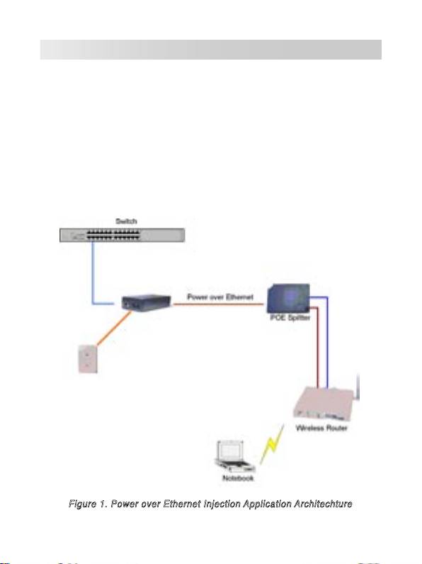
The ASUS EI-102 Power over Ethernet (PoE) Injector provides data and
power transmission on a single Ethernet cable. It works together with other
PoE devices such as Access Point (AP), PoE splitter or other equipments
that support IEEE 802.3af standard. The PoE injector detects connected,
IEEE 802.3af compatible devices and provides power to these device; if the
connected device does not support IEEE 802.3af standard, only data flow
could be transmitted. The PoE injector is usually installed near the Ethernet
switch or hub. The following figure shows a PoE network architechture.
Ethernet
Power
C
Power Cord
C
able
able
Figure 1. Power over Ethernet Injection Application Architechture
2
Features
• IEEE802.3af compatible Power Over Ethernet Injector
• Remote power feeding
• Short circuit protection
• RJ-45 port based data-power injection
• Power delivery up to 100 meters
• Light weight and compact size
• Plug-and-Play
Hardware Description
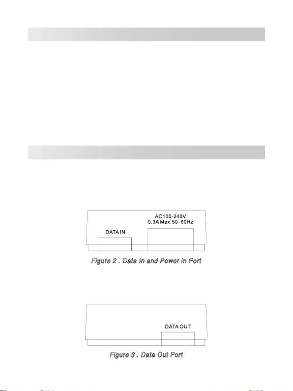
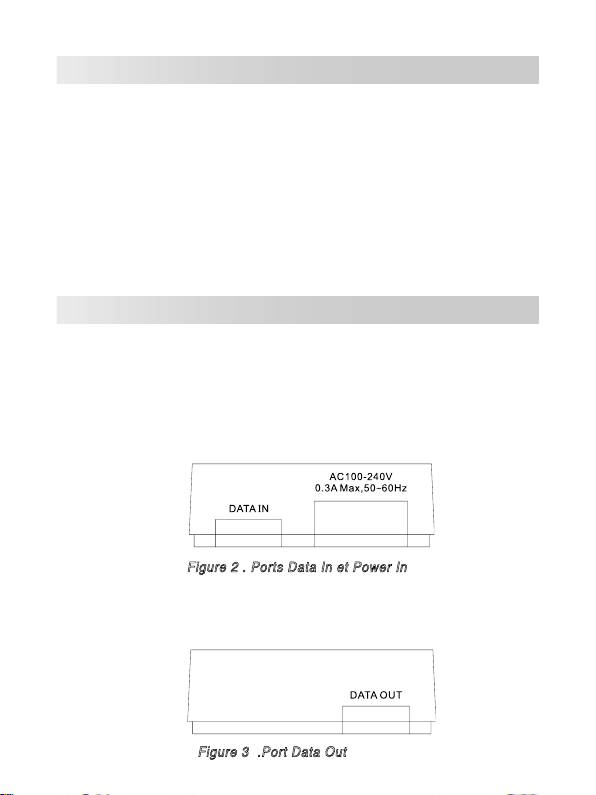
The Power over Ethernet Injector has three connection ports. They are:
•
Data In port:
An RJ-45 Ethernet port for connection with a switch.
•
Power In port:
Power supply port.
Figure 2 . Data In and Power in Port
•
Data Out port:
An RJ-45 Ethernet port with fixed RJ-45 cable for
connection with PoE Splitter or PD.
Figure 3 . Data Out Port
3
Installation
Please follow the steps below to install the PoE Injector:
1. Connect the
Data In
port to an RJ-45 port in your switch or hub via an
Ethernet cable.
2. Connect the
Data Out
port with a PoE Splitter, PD (such as router,
Access Point...etc.) or PoE Hub via an Ethernet cable.
3. Plug the power cord of the PoE Injector to the wall power jack.
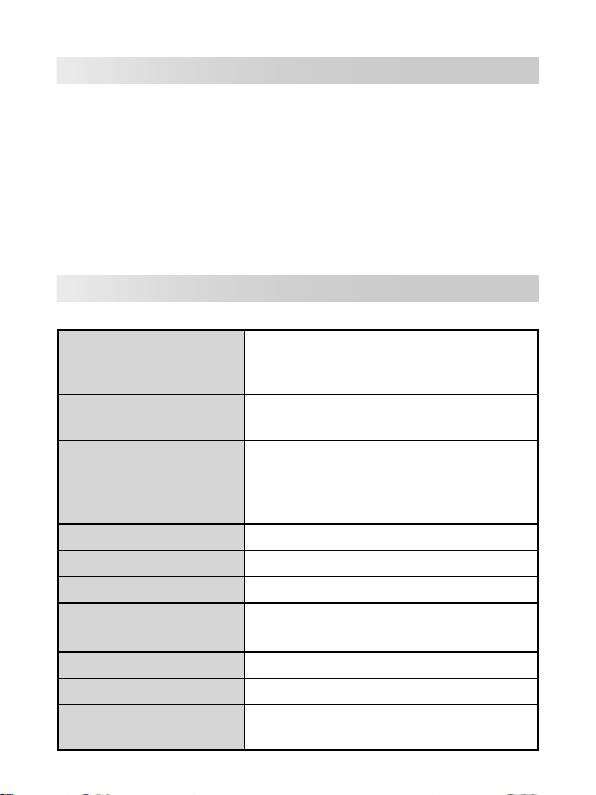
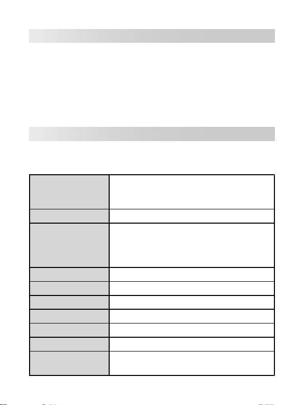
Technical Specification
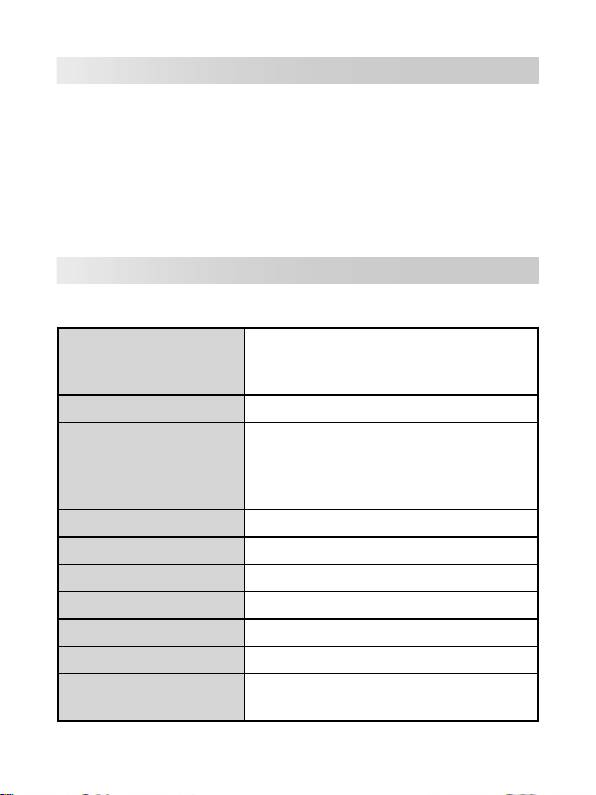
The following table shows the technical specification of the PoE Injector.
IEEE802.3 10BASE-T
Standard
IEEE802.3u 100BASE-T
IEEE802.3af
Connector
DC Out: Power pin: 4,5 (V+), 7,8 (V-)
10BASE-T: 2 pair UTP/STP Cat.3,4,5 cable
EIA/TIA-568 100-ohm (100m)
Network Cable
100BASE-TX: 2 pair UTP/STP Cat.5 cable
EIA/TIA-568 100-ohm (100m)
LED
System: power (green)
Power Input
Input Power: 100~240V, 50~60Hz, 0.3A
Output Power
48V DC, 0.3A
Operating environment
0˚C~40˚C; 90% Humidity (non-condensing)
Storage Temperature
0˚C~70˚C
Dimension
117mm x 60mm x 35mm (L x W x H)
FCC Class B, CE, UL, cUL, CE/EN60950,
EMI & Safety
VCCI, MIC, CCC
4

Power over Ethernet Injector
Guide de l’utilisateur
EI-102
5
Vue générale
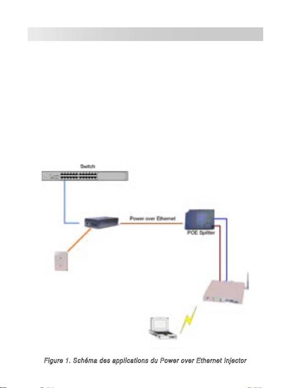
Le Power over Ethernet (PoE) Injector fournit données et alimentation
secteur, via un câble Ethernet, vers un appareil compatible PoE, tel que
AP, PoE splitter, ou dʼautres équipements supportant le standard IEEE
802.3af. Lʼinjecteur supporte le standard IEEE 802.3af pouvant détecter
le périphérique connecté, compatible IEEE 802.3af, et lʼalimenter en
courant électrique. Si lʼinjecteur détecte que le périphérique nʼest pas à la
norme IEEE 802.3af, celui-ci ne pourra pas être alimenté. Lʼinjecteur est
généralement installé à coté dʼun hub Ethernet. La figure suivante est un
schéma des applications du Power over Ethernet Injector.
Câble d'alimentation
Câble
Ethernet
Cordon d'alimetation
Routeur sans fil
PC portable
Figure 1. Schéma des applications du Power over Ethernet Injector
6
Fonctions
• Compatible avec la norme IEEE802.3af
• Alimentation à distance
• Protection contre les courts-circuits
• Associe Ethernet et alimentation dans un port RJ-45
• Fournit une alimentation jusquʼà 100 mètres
• Léger et taille compacte
• Plug-and-Play
Description matérielle
Le Power over Ethernet Injector possède trois ports de connexion ainsi quʼune
LED dʼactivité. Vous trouverez ci-dessous une description de chaque port.
•
Data In port:
Port réservé à un câble Ethernet RJ-45 pour la transmission
de données vers le PoE Injector. Sert à être connecté au switch.
•
Power In port:
Approvisionne lʼinjecteur en courant électrique.
Figure 2 . Ports Data In et Power In
•
Data Out port:
Port réservé à un câble Ethernet RJ-45 pour se
connecter à un PoE Splitter, ou PD (Powered devices).
Figure 3 .Port Data Out
7
Installation
Pour installer le Power over Ethernet Injector, veuillez suivre les étapes
suivantes.
1. Utilisez un câble RJ-45 pour connecter le port
Data in
du Power over
Ethernet Injector à un Hub/Switch.
2. Connectez le port
Data Out
à un PoE Splitter, PD (sPowered Devices: tel
quʼun Routeur, Access Point...etc.) ou à un Hub PoE.
3. Plug the power cord of the PoE Injector to the wall power jack.
Spécifications techniques
Le tableau suivant fournit les spécifications techniques du PoE Injector.
IEEE802.3 10BASE-T
Standards
IEEE802.3u 100BASE-T
IEEE802.3af
DC Out: Broche dʼalimentation: 4,5 (V+), 7,8
Connecteur
(V-)
10BASE-T: Câble 2 pair UTP/STP Cat.3,4,5
EIA/TIA-568 100-ohm (100m)
Câble réseau
100BASE-TX: Câble 2 pair UTP/STP Cat.5
EIA/TIA-568 100-ohm (100m)
LED
Système: alimentation (vert)
Entrée d'alimentation
100~240V, 50~60Hz, 0.3A
Sortie d'alimentation
48V DC, 0.3A
Température de
0˚C~40˚C; 90% d'humidité (sans
fonctionnement
condensation)
Température de stockage
0˚C~70˚C
Dimensions
117mm x 60mm x 35mm (L x P x H)
FCC Class B, CE, UL, cUL, CE/EN60950,
EMI & Safety
VCCI, MIC, CCC
8

Ethernet-Spannungsinjektor
Benutzeranleitung
EI-102
9
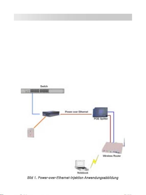
Übersicht
Der Ethernet-Spannungsinjektor (Power over Ethernet Injector) stellt die
Gleichspannungsversorgung und die Daten für PoE–Geräte, wie APs,
PoE-Splitter oder andere Ausrüstung, die den IEEE 802.3af-Standard
unterstützen, durch das Ethernetkabel zur Verfügung. Der Injektor
unterstützt den IEEE 802.3af-Standard welcher die angeschlossenen IEEE
802.3af-Geräte erkennt und ihnen die Spannung zur Verfügung stellt.
Wenn der Injektor Geräte erkennt, die IEEE 802.3af nicht unterstützen,
stellt er diesen auch keine Spannung zur Verfügung. Der Injektor sollte
normalerweise nahe dem Netzwerk-HUB installiert werden. Die folgende
Abbildung zeigt die Anwendung des PoE-Injektors.
Stromversorgungskabel
Ethernet-Kabel
Netzkabel
Bild 1. Power-over-Ethernet-Injektion Anwendungsabbildung
10
Funktionen
• IEEE802.3af kompatibler Power Over Ethernet Injector
• Spannungsferneinspeisung
• Kurzschlussschutz
• Ethernet und Spannungsversorgung kombiniert im RJ-45-Anschluss
• Liefert die Spannung bis zu 100 Meter weit
• Leicht und kompakte Bauweise
• Plug-and-Play
Hardware-Beschreibung
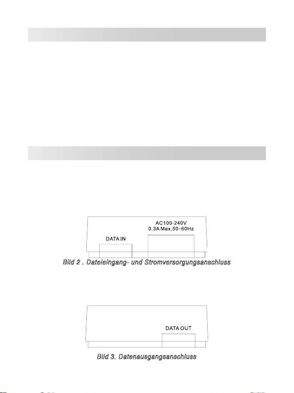
Der Ethernet-Spannugnsinjektor hat drei Anschlüsse. Diese sind:
•
Dateneingangsanschluss:
Ein RJ-45-Ethernet-Anschluss zur Verbin-
dung mit einem Switch.
•
Netzanschluss:
Stromversorgungsanschluss.
Bild 2 . Dateieingang- und Stromversorgungsanschluss
•
Datenausgangsanschluss:
Ein RJ-45-Ethernet-Anschluss mit fest
angeschlossenem RJ-45-Kabel zur Verbindung mit dem PoE-Splitter
oder PD.
Bild 3. Datenausgangsanschluss
11
Installation
Bitte befolgen Sie die Schritte, um den PoE-Injector zu installieren:
1. Verbinden Sie den
Dateneingangsanschluss
mit einem RJ-45-
Anschluss an Ihrem Switch oder Hub mittels eines Ethernet-Kabels.
2. Verbinden Sie den
Datenausgangsanschluss
mit dem PoE-Splitter, PD
(z.B. Router, Access Point etc.) oder PoE-Hub mit einen Ethernet-Kabel.
3. Stecken Sie den Netzstecker des PoE-Injektors in die Steckdose.
Technische Daten
Die folgende Tabelle zeigt Ihnen die technischen Daten des Ethernet-
Spannungsindikators.
IEEE802.3 10BASE-T
Standard
IEEE802.3u 100BASE-T
IEEE802.3af
Verbindung
Gleichspannungsausg.: Pin 4,5 (V+), 7,8 (V-)
10BASE-T: 2 Pair UTP/STP Cat.3,4,5 Kabel
EIA/TIA-568 100-Ohm (100m)
Netzwerkkabel
100BASE-TX: 2 Pair UTP/STP Cat.5 Kabel
EIA/TIA-568 100-Ohm (100m)
LED
System: Betriebsanzeige (grün)
Eingangsspannung
Eingangsspannung: 100-240V, 50-60Hz, 0,3A
Ausgangsspannung
48V Gleichspannung, 0,3A
Betriebsbedingungen
0˚C-40˚C; 90% nicht kondensierende Luftfeuchtigkeit
Lagertemperatur
0˚C-70˚C
Abmessungen
117mm x 60mm x 35mm (L x B x H)
FCC Klasse B, CE, UL, cUL, CE/EN60950,
EMI & Sicherheit
VCCI, MIC, CCC
12

Iniettore PoE (Power over Ethernet)
Guida dell’utente
EI-102
13

Overview
Lʼiniettore ASUS EI-102 PoE (Power over Ethernet) fornisce la trasmissione
di dati ed alimentazione con un singolo cavo Ethernet. Funziona insieme
ad altri dispositivi PoE come punti dʼaccesso, separatori PoE o altre
attrezzature che supportano lo standard IEEE 802.3af. Lʼiniettore PoE rileva
i dispositivi collegati compatibili IEEE 802.3af e fornisce loro alimentazione;
se i dispositivi collegati non supportano lo standard IEEE 802.3af, potrà
essere trasmesso solo il flusso dei dati. Lʼiniettore PoE di solito è installato
vicino allʼhub o commutatore Ethernet. La figura che segue mostra
unʼarchitettura di rete PoE.
Commutatore
PoE (Power over Ethernet)
Cavo dʼalimentazione
Separatore PoE
Cavo Ethernet
Cavo dʼ
alimentazione
Wireless Router
noterbook
Figura 1. Architettura applicazione Iniettore PoE (Power over Ethernet)
14
Features
• Iniettore PoE (Power over Ethernet) compatibile IEEE802.3af
• Alimentazione remota
• Protezione da cortocircuito
• Iniezione dati/alimentazione basata su porta RJ-45
• Distribuzione alimentazione fino a 100
• Peso leggero e dimensioni compatte
• Plug and Play
Descrizione dell’hardware
The Power over Ethernet Injector has three connection ports. They are:
•
Data In port:
An RJ-45 Ethernet port for connection with a switch.
•
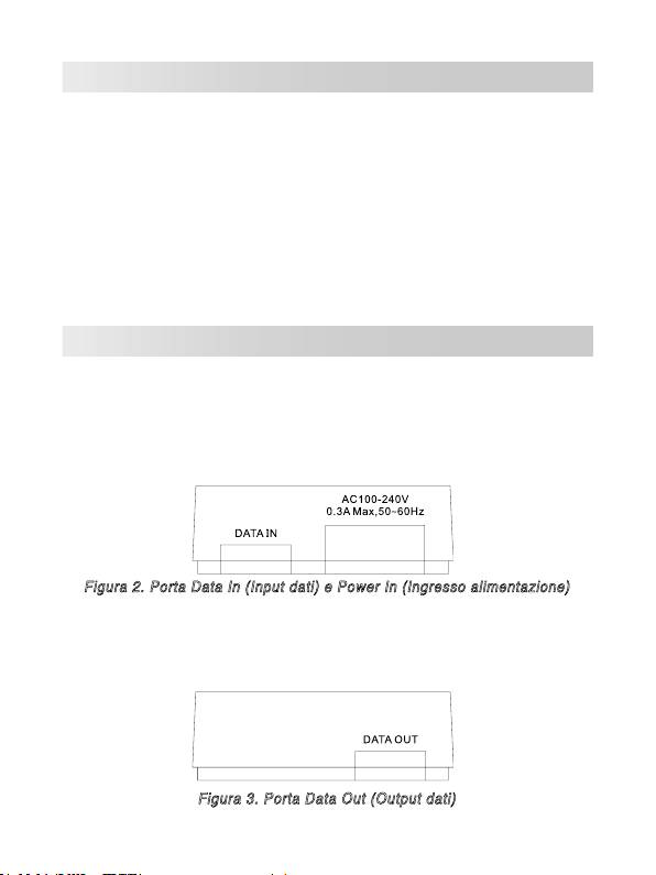
Porta Power In (Input alimentazione): porta di fornitura
dellʼalimentazione.
Figura 2. Porta Data In (Input dati) e Power In (Ingresso alimentazione)
•
Porta Data Out (Output dati): una porta Ethernet RJ-45 con un
cavo fisso RJ-45 per eseguire il collegamento al separatore PoE o
PD.
Figura 3. Porta Data Out (Output dati)
15

Installazione
Attenersi alle fasi che seguono per installare lʼIniettore PoE:
1. Collegare la porta Data In (Input dati) ad una porta RJ-45 del
commutatore o dellʼhub usando un cavo Ethernet.
2. Collegare la porta Data Out (Output dati) al Separatore PoE, PD (come
router, punto dʼaccesso, eccetera) o hub PoE, usando un cavo Ethernet.
3. Collegare il cavo dʼalimentazione dellʼIniettore PoE alla presa a muro.
Specifiche tecniche
La tabella che segue fornisce le specifiche tecniche dellʼIniettore PoE.
IEEE802.3 10BASE-T
Standard
IEEE802.3u 100BASE-T
IEEE802.3af
Connettore
Output CD: Pin alimentazione: 4,5 (V+); 7,8 (V-)
10BASE-T: cavo UTP/STP categoria 3, 4, 5 doppio
EIA/TIA-568 100-ohm (100m)
Cavo di rete
100BASE-TX: cavo UTP/STP categoria 5 doppio
EIA/TIA-568 100-ohm (100m)
LED
Sistema: alimentazione (verde)
Input potenza
Potenza dʼinput: 100~240V, 50~60Hz, 0.3A
Potenza dʼoutput
48V DC, 0.3A
Ambiente operativo
0˚C~40˚C; 90% di umidità (senza condensa)
Temperatura dʼ
0˚C~70˚C
immagazzinamento
Dimensioni
117mm x 60mm x 35mm (L x P x A)
FCC Class B, CE, UL, cUL, CE/EN60950, VCCI,
EMI e Sicurezza
MIC, CCC
16

Inyector de Energía sobre Ethernet
EI-102
Manual del Usuario
17
Introducción
El inyector de energía Power over Ethernet proporciona datos y
alimentación por corriente alterna a través de cables Ethernet u otros
dispositivos equipados con PoE, tales como AP, Distribuidor PoE o
cualquier otro dispositivo que soporte el estándar IEEE 802.3af. Si el
inyector detecta que el dispositivo conectado no soporta el estándar IEEE
802.3af éste no podrá recibir energía desde el inyector. El inyector se
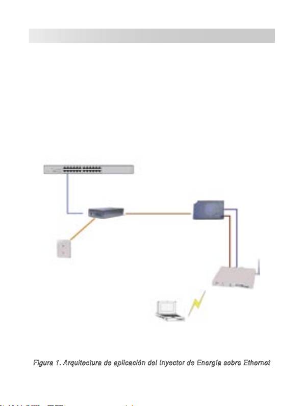
instala típicamente cerca del hub Ethernet. La siguiente figura ilustra una
aplicación del inyector Power over Ethernet.
18
Switch
Cable de alimentación
Power over Ethernet
Cable Ethernet
Cable Ethernet
Cable de
alimentación
Enrutador
Inalámbrico
PC Portátil
Figura 1. Arquitectura de aplicación del Inyector de Energía sobre Ethernet
Características
• Inyector de Energía sobre Ethernet compatible con IEEE802.3af
• Alimentación de energía remotamente
• Protección contra cortocircuitos
• Inyección de energía basada en puertos RJ-45
• Entrega de energía a hasta 100 metros
• Diseño ligero y de tamaño compacto
• Conexión en caliente Plug-and-Play
Descripción del Hardware
El Inyector de Energía tiene tres puertos de conexión. Estos son:
•
Puerto de Entrada de Datos:
Puerto Ethernet RJ-45 para conectar
con un Switch.
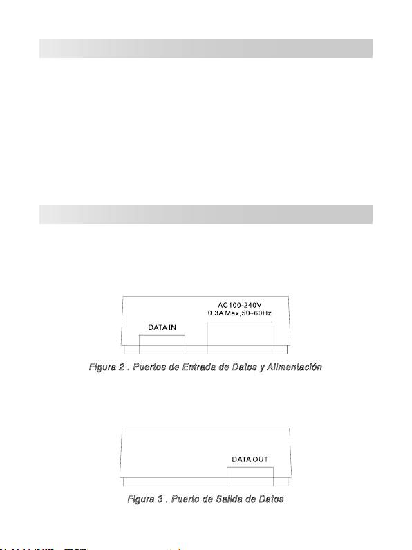
•
Puerto de Entrada de Alimentación
Figura 2 . Puertos de Entrada de Datos y Alimentación
•
Puerto de Salida de Datos:
Puerto Ethernet RJ-45 con un cable
RJ-45 fijo para conexión con Distribuidores PoE u otros dispositivos.
Figura 3 . Puerto de Salida de Datos
19
