Asus T5-P5G41E: instruction
Class: Computer equipment, hardware, accessories
Type:
Manual for Asus T5-P5G41E
Table of contents
- Internal components Removing the cover
- Lifting the power supply unit Installing a CPU Installing an Intel CPU
- Installing an AMD CPU Installing the CPU fan and heatsink assembly Installing an Intel CPU heatsink and fan
- Installing an AMD CPU heatsink and fan Installing a DIMM
- Installing an expansion card Installing a hard disk drive
- Installing an optical drive Reinstalling the cover
English
T5-Series
ASUS PC (Desktop Barebone)
Installation manual
Download the latest manual from the ASUS website: www.asus.com
u5335_T5_series_qsg.indb 1 1/29/10 3:55:42 PM
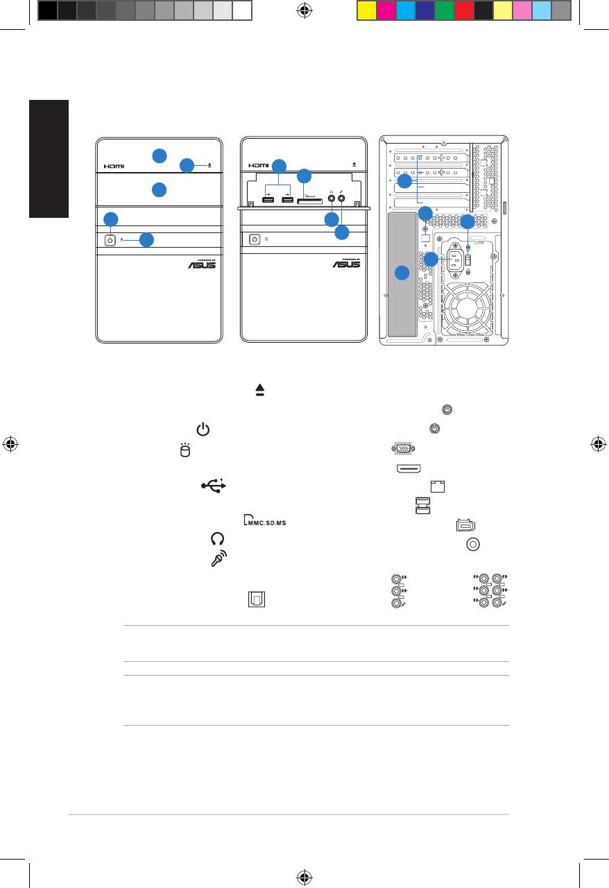
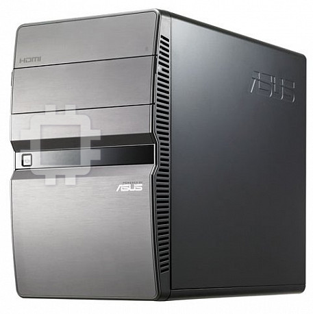
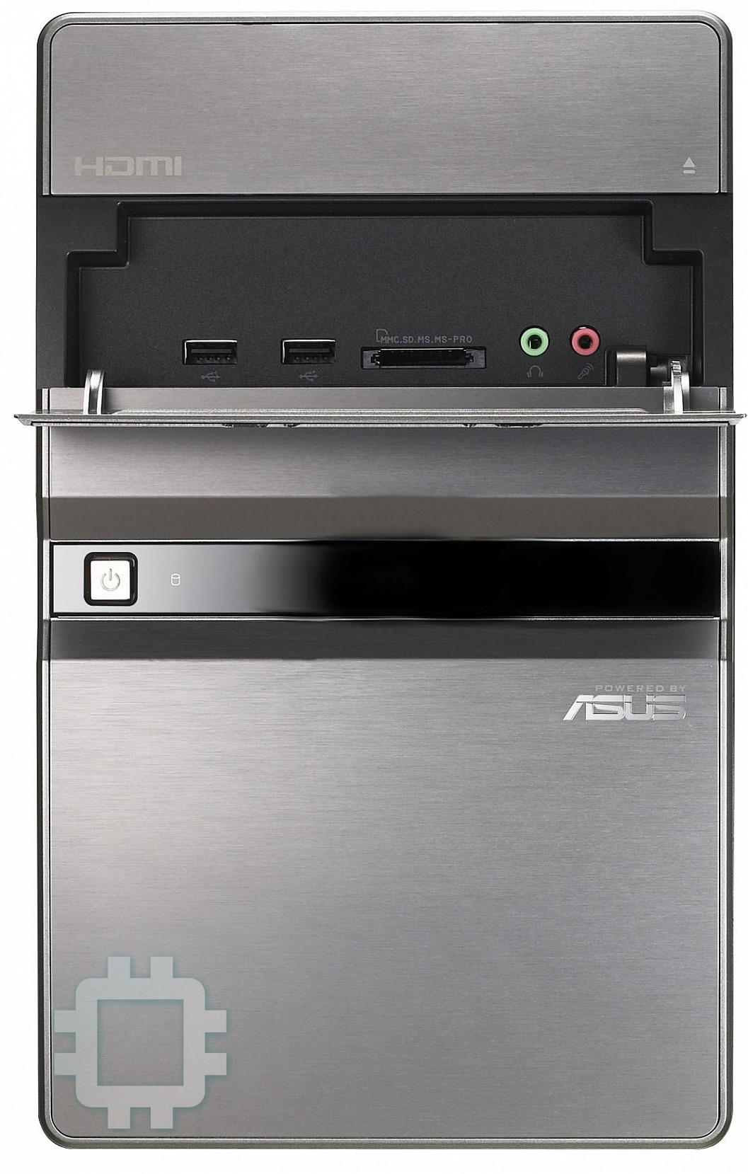
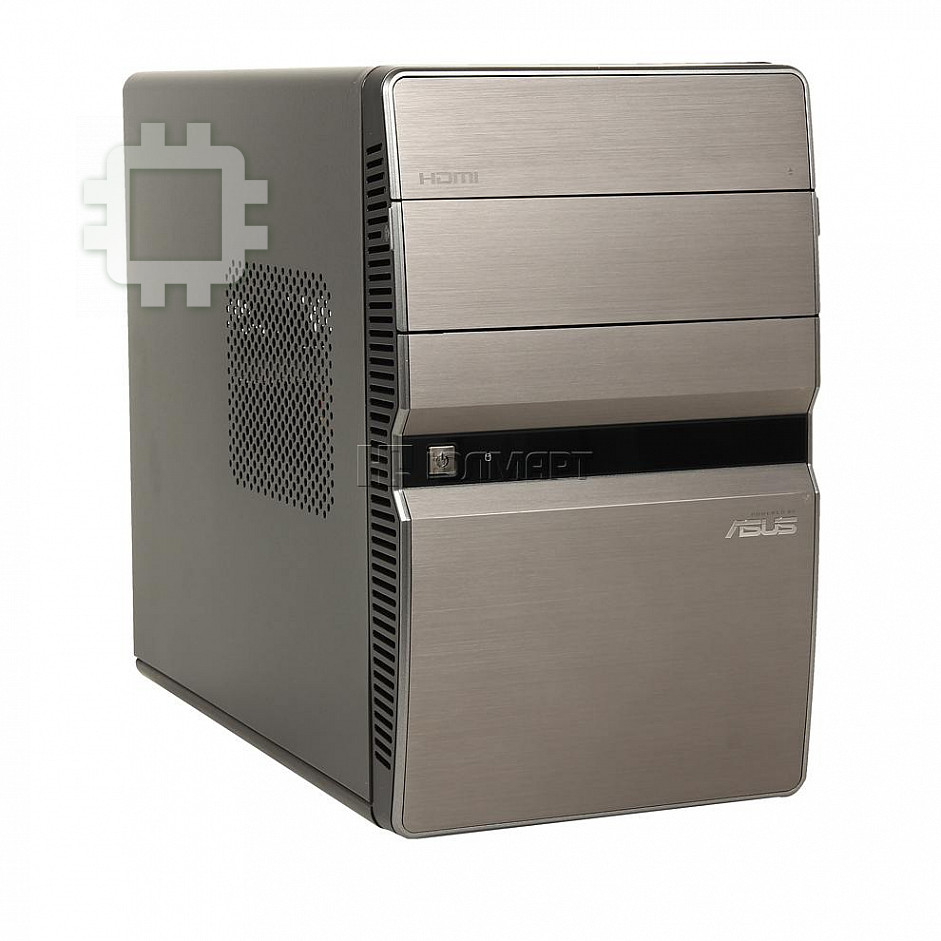
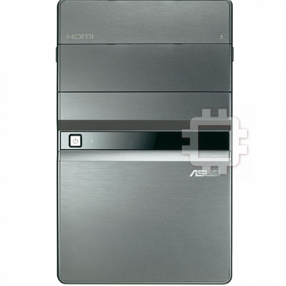
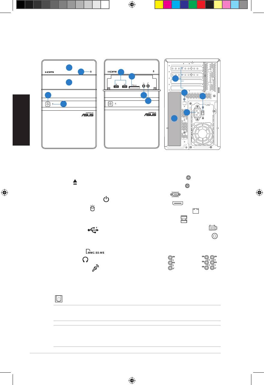
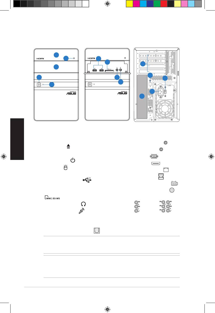
Front/Rear panel features
English
1. Optical drive bay cover
12.** Voltage selector switch
2. Optical drive eject button ( )
13. Power connector
3. Front I/O ports cover
14.* • PS/2 keyboard port ( )
4. Power button ( )
• PS/2 mouse port ( )
• VGA port ( )
5. HDD LED ( )
(lights up when
the hard disk drive operates)
• HDMI port ( )
6. USB 2.0 ports ( )
• LAN (RJ-45) port ( )
7. MultiMediaCard / Secure Digital /
• USB 2.0 ports ( )
Memory Stick card slot ( )
• 6-pin IEEE 1394a port ( )
8. Headphone port ( )
• Coaxial S/PDIF Out port ( )
9. Microphone port ( )
•Audioportscongurations:
10. Expansion slot metal brackets
11.* Optical S/PDIF Out port ( )
• 6-channel
2 Installation manual
L
IN
IN
E
FR
O
N
T
M
IC
IN
• 8-channel
C
BA
T
S
S
R
L
IN
IN
E
R
S
E
P
A
K
R
FR
O
N
T
S
S
P
ID
K
E
M
IC
IN
NOTE: *The front/rear panel ports and their locations may vary, depending on the
model of your system. For detailed descriptions, refer to the system User Guide.
NOTE:**Thesystem’spowersupplyunithasa115V/230Vvoltageselectorswitch
located beside the power connector. Use this switch to select the appropriate system
input voltage according to the voltage supply in your area.
SPDIF OUT
SATA
Front (Close)
Front (Slide open)
Rear
1
2
6
7
10
3
11
4
8
12
9
5
13
14
u5335_T5_series_qsg.indb 2 1/29/10 3:55:54 PM
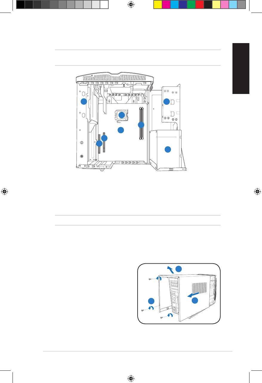
Internal components
NOTE: The illustration below shows the internal view of the system when you remove
the cover and lift the power supply unit.
English
1
2
5
4
6
7
8
3
1. 5.25-inch optical drive cage
5. CPU socket
2. 3.5-inch hard disk drive cage
6.* ASUS motherboard
3. Power supply unit
7. PCI Express x16 slot
4. DIMM sockets
8. PCI slot
NOTE: *Refer to the system User Guide for motherboard details.
Removing the cover
1. Remove the three cover screws on
3
the rear panel. Keep the screws for
later use.
2. Pull the cover toward the rear panel.
3. Lift the cover, then set it aside.
1
2
3Installation manual
u5335_T5_series_qsg.indb 3 1/29/10 3:55:55 PM
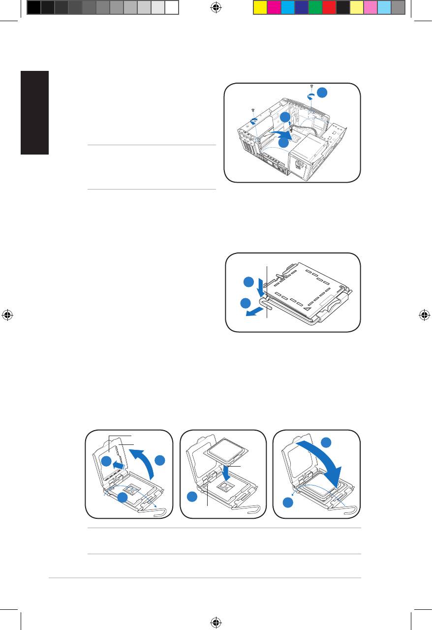
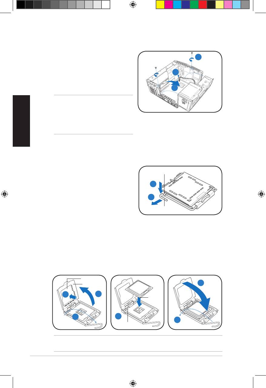
Lifting the power supply unit
1. Locate and remove the two screws.
English
1
2. Remove the 4-pin ATX 12V power
cable.
2
3. Lift the PSU in the direction of the
arrow to a 90º angle.
3
CAUTION: When removing the PSU,
makesuretoholdorsupportitrmly.
The unit might accidentally drop and
damage the other system components.
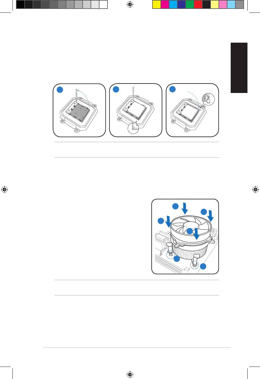
Installing a CPU
®
Installing an Intel
CPU
1. Locate the CPU socket on the
Retention tab
motherboard.
2. Press the load lever with your
2A
thumb (2A), then move it to the left
(2B) until it is released from the
2B
retention tab.
Load lever
3. Lift the load lever in the direction of
the arrow to a 135º angle.
4. Lifttheloadplatewithyourthumbandforengertoa100ºangle(4A),then
push the PnP cap from the load plate window to remove (4B).
5. Position the CPU over the socket, making sure that the gold triangle is on the
bottom-left corner of the socket. Fit the socket alignment key into the CPU
notch.
6. Close the load plate (6A), then push the load lever (6B) until it snaps into the
retention tab.
PnP cap
Load plate
6A
Gold
4B
4A
triangle
mark
3
5
6B
Alignment key
CAUTION: Incorrect installation of the CPU into the socket may bend the pins and
severely damage the CPU.
4 Installation manual
u5335_T5_series_qsg.indb 4 1/29/10 3:55:58 PM
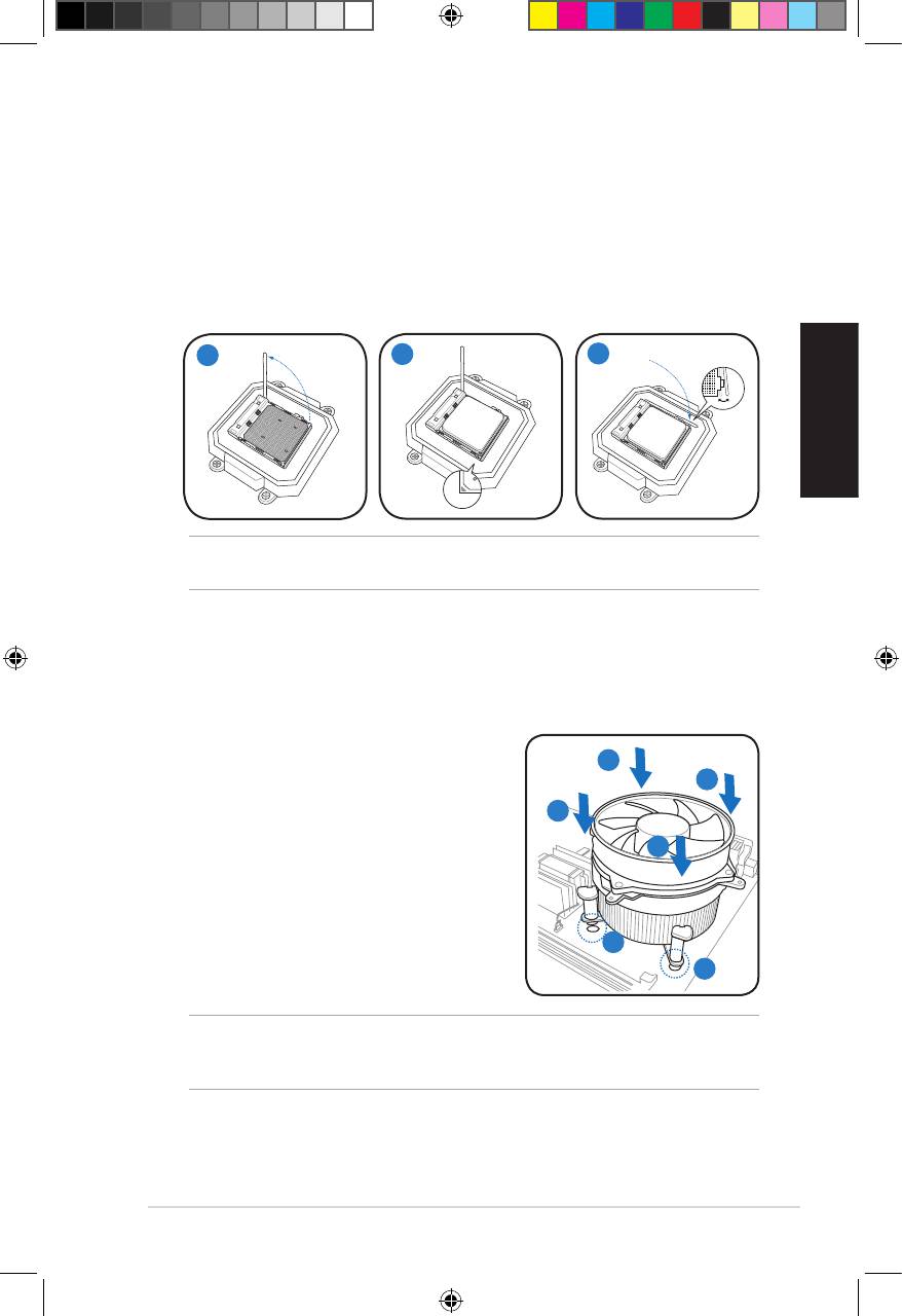
Installing an AMD CPU
1. Locate the CPU socket, then lift the socket lever to a 90º angle.
2. Install the CPU to the socket, making sure that the CPU corner with the gold
triangle matches the socket corner with a small triangle.
3. Push down the socket lever to secure the CPU.
English
1
2
3
CAUTION: Incorrect installation of the CPU into the socket may bend the pins and
severely damage the CPU.
Installing the CPU fan and heatsink assembly
®
Installing an Intel
CPU heatsink and fan
1. Place the heatsink on top of the installed
A
CPU, making sure that the four fasteners
B
match the holes on the motherboard.
B
2. Push down two fasteners at a time in a
diagonal sequence to secure the heatsink
A
and fan assembly in place.
3. When the fan and heatsink assembly is in
place, connect the CPU fan cable to the
connector on the motherboard.
1
1
CAUTION. Do not forget to connect the CPU fan connector! Hardware monitoring error
can occur if you fail to plug this connector.
5Installation manual
u5335_T5_series_qsg.indb 5 1/29/10 3:56:01 PM
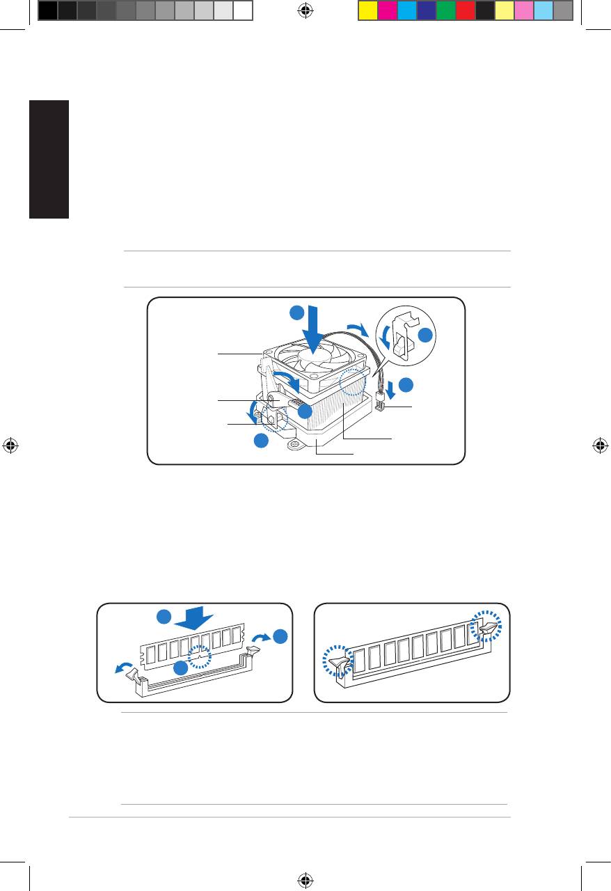
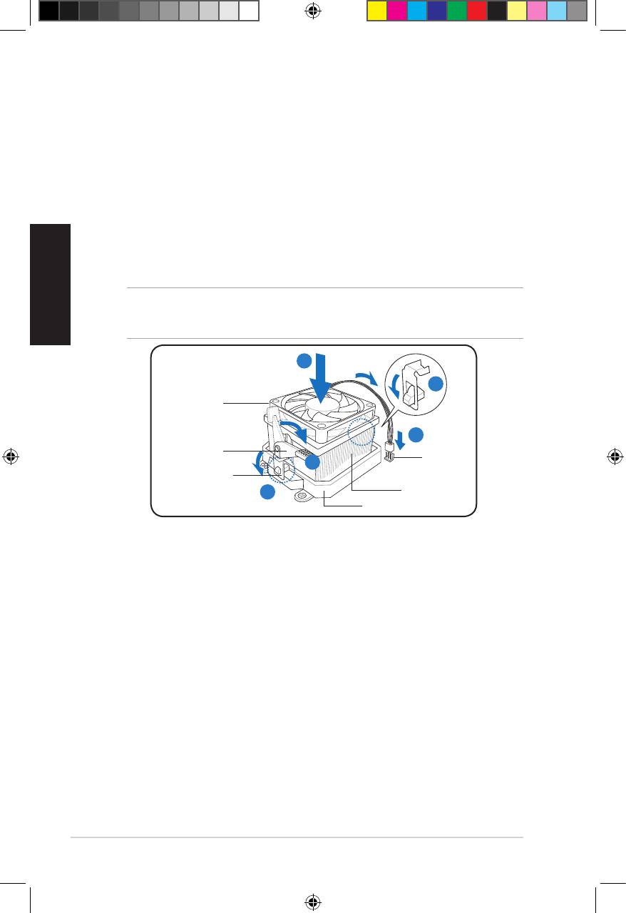
Installing an AMD CPU heatsink and fan
English
1. Place the heatsink on top of the installed CPU.
2. Attach one end of the retention bracket to the retention module base.
3. Attach the other end of the retention bracket (near the retention bracket lock)
to the retention module base until it clicks in place.
4. Push down the retention bracket lock on the retention mechanism to secure
the fan and heatsink to the module retention module base.
5. Connect the CPU fan cable to the connector on the motherboard.
CAUTION. Do not forget to connect the CPU fan connector! Hardware monitoring error
can occur if you fail to plug this connector.
1
2
CPU fan
5
Retention
CPU fan
bracket lock
4
connector
Retention bracket
3
CPU heatsink
Retention module base
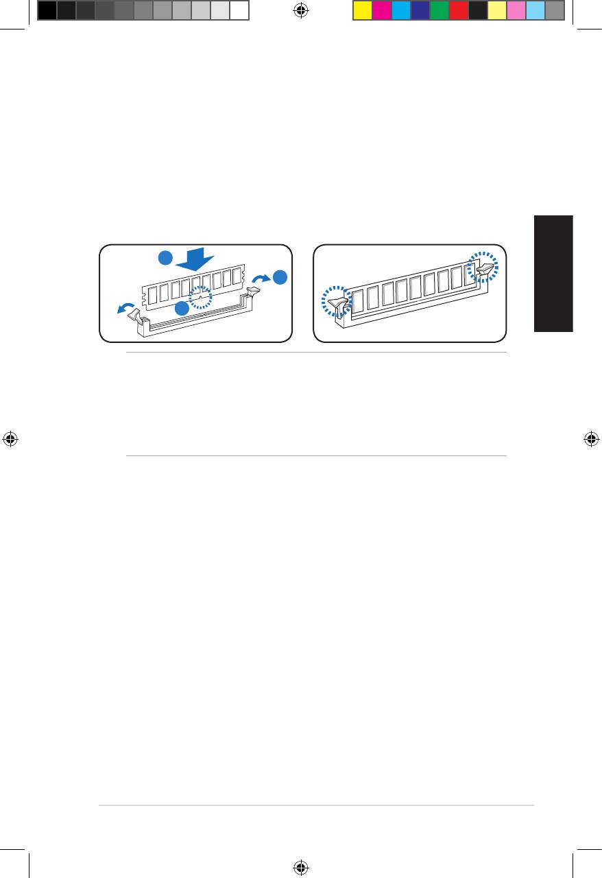
Installing a DIMM
1. Locate the DIMM sockets in the motherboard.
2. Unlock a DIMM socket by pressing the retaining clips outward.
3. Align a DIMM on the socket such that the notch on the DIMM matches the
break on the socket.
4. Push the DIMM to the socket until the retaining clips snap inward.
4
2
3
CAUTION:
• Unplug the power supply before adding or removing DIMMs. Failure to do so may
cause damage to the motherboard and/or components.
• ADDRDIMMiskeyedwithanotchsothatittsinonlyonedirection.Donotforce
a DIMM into a socket to avoid damaging the DIMM.
6 Installation manual
u5335_T5_series_qsg.indb 6 1/29/10 3:56:03 PM
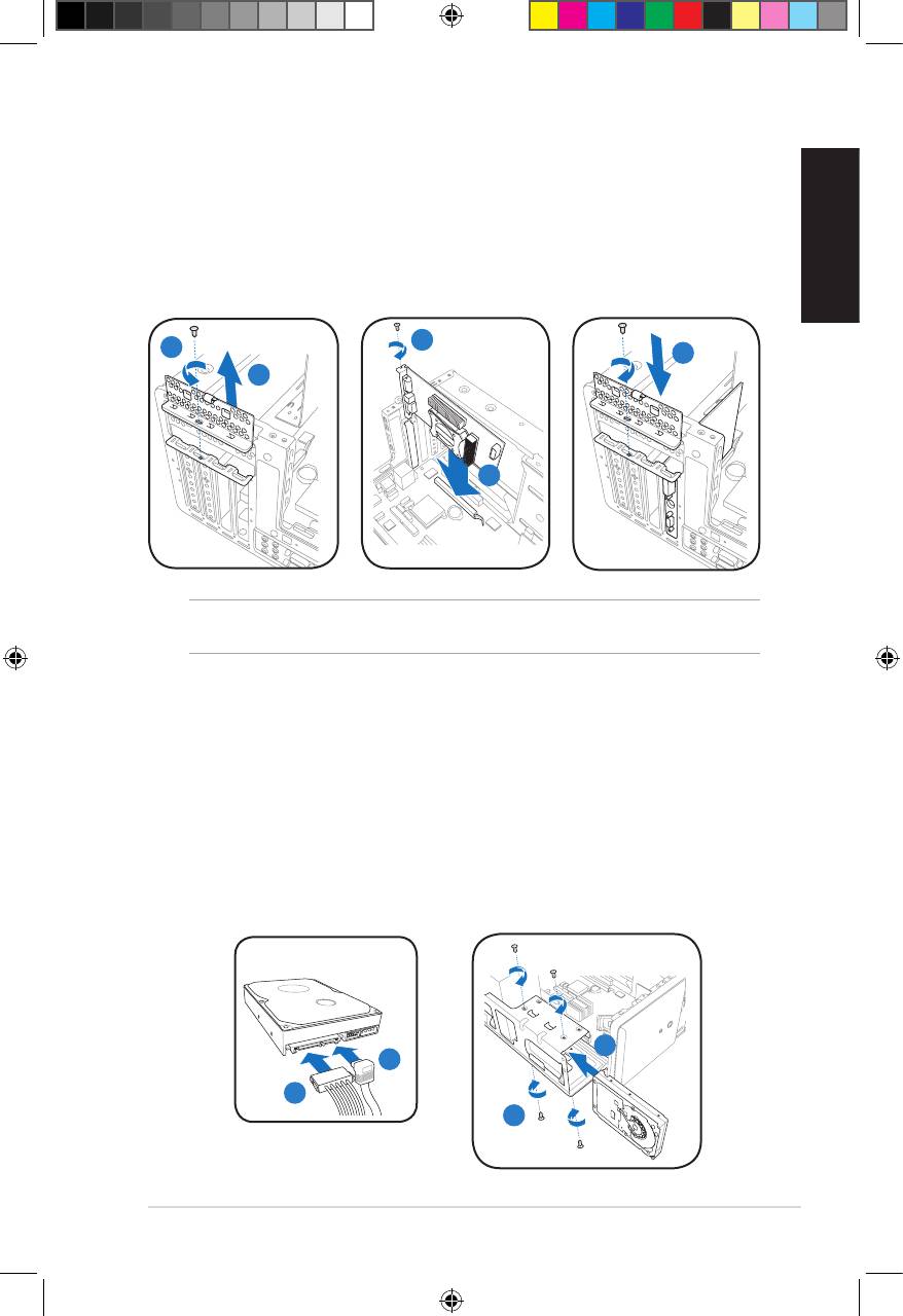
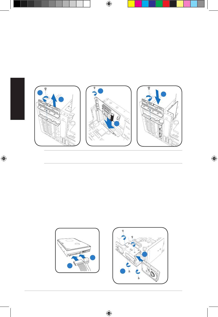
Installing an expansion card
1. Locate and remove one metal bracket lock screw.
2. Remove the metal bracket lock.
3. Alignthecardconnectorwiththeslot,thenpressrmly.
4. Secure the card with one screw.
English
5. Replace the metal braket lock, then secure it with one screw.
4
1
5
2
3
IMPORTANT. This chassis supports PCI Express x 16 cards with 192mm x 19mm or
smaller dimensions only.
Installing a hard disk drive
1. Connect the SATA signal (1A) and power (1B) plugs to the connectors at the
back of the SATA hard disk drives.
2. Locate the HDD tray.
3. Insert a hard disk drive (with the HDD PCB facing the top of the chassis) to
the tray, then secure it with four screws.
4. Connect the SATA signal cable to the SATA connector on the motherboard, and
tighten all the cables with the plastic coils.
SATA
3
1A
1B
3
7Installation manual
u5335_T5_series_qsg.indb 7 1/29/10 3:56:06 PM
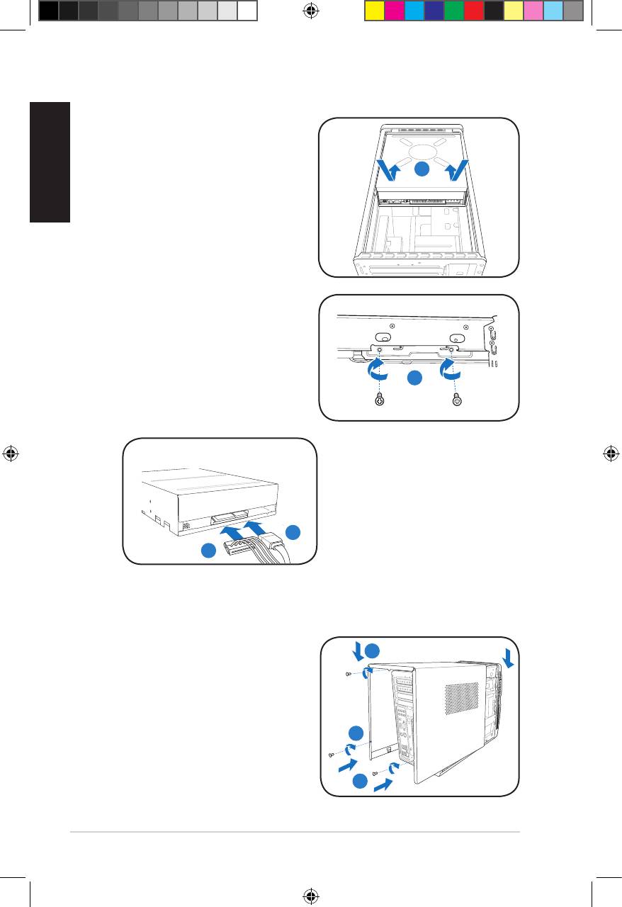
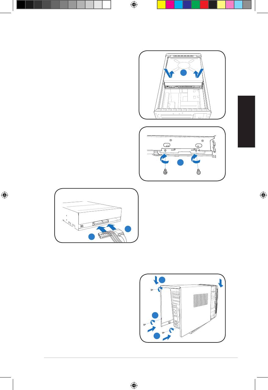
Installing an optical drive
1. Place the chassis upright.
English
2. Insert the SATA optical drive to
the upper 5.25 in drive bay, then
2
carefully push the drive until its
screw holes align with the holes on
the bay.
3. Secure the optical drive with four
screws on both sides of the bay.
4. Connect the SATA signal (4A) and
power plugs (4B) to the connectors
at the back of the SATA drive.
3
SATA
4A
4B
Reinstalling the cover
1. Fit the cover tabs with the chassis rail
1B
and the front panel tabs (1A), then
lower the rear edge of the cover as
shown (1B).
2. Secure the cover with three screws.
2
1A
8 Installation manual
u5335_T5_series_qsg.indb 8 1/29/10 3:56:09 PM

Séries T5
Français
ASUS PC (Système Barebone)
Manuel d’installation
Téléchargez les derniers manuels sur le site Web d'ASUS : www.asus.com
u5335_T5_series_qsg.indb 9 1/29/10 3:56:11 PM
Caractéristiques du panneau avant/arrière
Français
1. Cache de la baie pour lecteur
12.** Interrupteur de sélection du voltage
optique
13. Connecteurd’alimentation
2. Boutond’éjectiondulecteur
14.* • Port clavier PS/2 ( )
optique ( )
• Port souris PS/2 ( )
3. Cachedumoduled’E/Savant
• Port VGA ( )
4. Boutond’alimentation( )
• Port HDMI ( )
5. LED disque dur ( )
(s’allume
• Port réseau (RJ-45) ( )
lorsque le disque dur lit/écrit des
• Ports USB 2.0 ( )
données)
• Port IEEE 1394a 6 broches ( )
6. Ports USB 2.0 ( )
• Port de sortie S/PDIF optique ( )
7. Slot carte MultiMediaCard /
Secure Digital /
•L’unedescongurationsdeports
Memory Stick ( )
audio suivantes :
8. Port casque ( )
• 6 canaux
9. Port microphone ( )
10. Supports métalliques pour cartes
d’extension
11.* Port de sortie S/PDIF optique
( )
10 Manueld’installation
L
IN
IN
E
FR
O
N
T
M
IC
IN
• 8 canaux
C
BA
T
S
S
R
L
IN
IN
E
R
S
E
P
A
K
R
FR
O
N
T
S
S
P
ID
K
E
M
IC
IN
REMARQUE : *Les ports du panneau arrière ainsi que leur emplacement, peuvent
varierenfonctiondesmodèles.Voirlemanueld’utilisationpourplusdétails.
REMARQUE :**Leblocd’alimentationdusystèmeintègreuninterrupteurdesélection
duvoltage(115V/230V)localiséàcôtéduconnecteurd’alimentation.Utilisezcet
interrupteur pour sélectionner le voltage en fonction de votre région.
SPDIF OUT
SATA
Avant (Fermé)
Avant (Ouvert)
Arrière
1
2
6
7
10
3
11
4
8
12
9
5
13
14
u5335_T5_series_qsg.indb 10 1/29/10 3:56:19 PM

Composants internes
REMARQUE : Les illustrations ci-dessous offrent une vue interne du système après
avoirretirélepanneaulatéraletleblocd’alimentation
1
2
5
4
Français
6
7
8
3
1. Baie pour lecteur optique 5.25”
5. Socket CPU
2. Baie pour lecteur de disque dur
6.* Carte mère ASUS
3.5”
7. Slot PCI Express x16
3. Blocd’alimentation
8. Slot PCI
4. Sockets pour modules mémoire
REMARQUE :*Reportez-vousaumanueld’utilisationpourplusdedétailssurlacarte
mère.
Retirer le panneau
latéral
3
1. Retirez les trois vis localisées à
l’arrièreduchâssis.Mettezlesvisde
côté.
2. Faites glisser le panneau latéral vers
1
2
l’arrière.
3. Soulevez le panneau, puis mettez-le
de côté.
11Manueld’installation
u5335_T5_series_qsg.indb 11 1/29/10 3:56:21 PM
Retirer le bloc d’alimentation
1. Localisez et retirez les deux vis.
1
2. Retirezlecâbled’alimentationATX
12V de 4 broches.
2
3. Soulevezleblocd’alimentationdans
ladirectiondelaècheetdansun
3
angle de 90º.
ATTENTION : Lorsque vous retirez e
blocd’alimentation,assurez-vousde
Français
le prendre fermement en main. Si vous
laisseztomberleblocd’alimentation,
celui-ci peut endommager les
composants du système.
Installer un CPU
®
Installer un CPU Intel
1. Locate the CPU socket on the
Onglet de rétention
motherboard.
2. Pressez le levier avec votre pouce
2A
(2A), et déplacez-le vers la gauche
(2B)jusqu’àcequ’ilsoitlibéréde
2B
son onglet de rétention.
Levier
3. oulevez le levier dans la direction
delaècheàunanglede135º.
4. Soulevez la plaque avec votre pouce et votre index à un angle de 100º (4A),
puis enlevez le couvercle PnP de la plaque (4B).
5. Placez le CPU sur le socket, en vous assurant que la marque en forme de
triangledoréestplacéeenbasàgauchedusocket.Lesergotsd’alignement
sur le socket doivent correspondre aux encoches du CPU.
6. Refermezlaplaque(6A),puispressezlelevier(6B)jusqu’àcequ’ilseloge
dans le loquet de rétention.
Cache PnP
Plaque
6A
4B
4A
Triangle
doré
3
5
6B
Ergotd’alignement
ATTENTION : Une mauvaise installation du CPU dans le socket peut tordre les
broches et sévèrement endommager le CPU !
12 Manueld’installation
u5335_T5_series_qsg.indb 12 1/29/10 3:56:23 PM
Installer un CPU AMD
1. Repérez le socket du CPU sur la carte mère, puis soulevez le levier à un
angle de 90º.
2. Placez le CPU sur le socket, en vous assurant que la marque en forme de
triangle doré est placée en bas à gauche du socket.
3. Abaissez le levier pour sécurisez le CPU
1
2
3
Français
ATTENTION : Une mauvaise installation du CPU dans le socket peut tordre les
broches et sévèrement endommager le CPU !
Installer l’ensemble ventilateur/dissipateur
®
Installer un ventilateur/dissipateur de CPU Intelnstaller un ventilateur/dissipateur de CPU Intel
1. Positionnez le dissipateur sur le CPU installé,
A
en vous assurant que les quatre attaches
B
correspondent aux trous sur la carte mère.
B
2. Enfoncez les attaches deux par deux selon
uneséquencediagonale,andexer
A
l’ensembleventilateur-dissipateur.
3. ConnectezlecâbleduventilateurCPU
au connecteur de la carte mère étiqueté
CPU_FAN.
1
1
ATTENTION : N’oubliezpasdeconnecterlecâbleduventilateurauconnecteurCPU
fan ! Des erreurs de surveillance pourraient se produire si vous ne branchez pas ce
connecteur.
13Manueld’installation
u5335_T5_series_qsg.indb 13 1/29/10 3:56:27 PM
Installer un ventilateur/dissipateur de CPU AMD
1. Positionnez le dissipateur sur le CPU installé.
2. Attachezl’undescrochetsderétentionàlabasedumodulederétention.
3. Alignezl’autrecrochetderétention(situéàcôtédusystèmedeverrouillage)
à la base du module de rétention. Un léger cliquetis vous informe que le
crochet est bien en place.
4. Abaissezlecrochetderétentionverslemécanismederétentionpourxerle
dissipateur et le ventilateur à la base du module.
Français
5. ConnectezlecâbleduventilateurduCPUauconnecteurCPU_FANdela
carte mère.
ATTENTION : N’oubliezpasdeconnecterlecâbleduventilateurauconnecteurCPU
fan ! Des erreurs de surveillance pourraient se produire si vous ne branchez pas ce
connecteur.
1
2
Ventilateur
du CPU
5
Système de
verrouillage
Connecteur
4
de ventilation
Crochet de
rétention
3
Dissipateur
Base du module de
rétention
14 Manueld’installation
u5335_T5_series_qsg.indb 14 1/29/10 3:56:28 PM
Installer un module mémoire
1. Localisez les sockets pour modules mémoire de la carte mère.
2. Déverrouillez un socket pour module mémoire en pressant le clip de rétention
versl’extérieur.
3. Alignezunmodulemémoiresurlesocketdesortequel’encochesurle
modulecorrespondeàl’ergotsurlesocket.
4. Insérezfermementlemodulemémoiredanslesocketjusqu’àcequeleclip
se remette en place de lui-même et que le module soit bien sécurisé.
4
2
Français
3
ATTENTION :
• Débranchezlasourced’alimentationavantd’ajouterouderetirerdesmodules
mémoire. Ne pas le faire peut endommager la carte mère et/ou les composants.
• UnmoduleDDRestverrouilléparuneencoche,desortequ’ilnepeutentrer
dans le socket que dans un seul sens. NE FORCEZ pas un module dans son
socketpouréviterdel’endommager.
15Manueld’installation
u5335_T5_series_qsg.indb 15 1/29/10 3:56:29 PM
Installer une carte d’extension
1. Enlevez le support métallique correspondant au slot dans lequel vous désirez
installer la carte.
2. Retirez le verrou du support métallique.
3. Insérezleconnecteurdelacartedansleslotetpressezjusqu’àcequelacarte
soit en place.
4. Sécurisezlacarteàl’aided’unevis.
5. Replacez le verrou et la vis du cache métallique.
Français
4
1
5
2
3
IMPORTANT : Seules des cartes PCI Express x 16 de 192mm x 19mm ou moins
peuventêtreinstalléessurcechâssis.
Installer un lecteur de disque dur
1. ConnectezlecâbledesignalSATA(1A)etd’alimentation(1B)surles
connecteurslocalisésàl’arrièredulecteurSATA.
2. Localisez la baie 3.5” pour disque dur.
3. Insérezledisquedur(avecl’étiquettefaceverslehautduchâssis)dansla
cageetsécurisez-leàl’aidedequatrevis.
4. ConnectezlecâbledesignalSATAauconnecteurSATAdelacartemère,puis
xezlescâblesensembleàl’aidedelaboucleenplastique.
SATA
3
1A
1B
3
16 Manueld’installation
u5335_T5_series_qsg.indb 16 1/29/10 3:56:31 PM
Installer un lecteur optique
1. Placezlechâssisenposition
verticale.
2. Insérez le lecteur optique SATA
2
danslabaie5.25”jusqu’àceque
les pas de vis du lecteur soient
alignés avec ceux de la baie.
3. Sécurisezlelecteuroptiqueàl’aide
Français
de deux vis de chaque côté de la
baie.
4. Connectezlescâblesdesignal(4A)
etd’alimentationSATA(4B)aux
connecteurs appropriés situés à
3
l’arrièredulecteur.
SATA
4A
4B
Réinstaller le panneau latéral
1. Insérez les onglets du panneau latéral
1B
surlesrailsduchâssis(1A),puis
abaissezl’arrièredupanneaucomme
illsutré ci-contre (1B).
2. Sécurisezlepanneaulatéralàl’aide
des trois vis précédemment mises de
2
côté.
1A
17Manueld’installation
u5335_T5_series_qsg.indb 17 1/29/10 3:56:34 PM
Français
18 Manueld’installation
u5335_T5_series_qsg.indb 18 1/29/10 3:56:34 PM
T5-Series
ASUS PC (Desktop Barebone)
Installationshandbuch
Deutsch
Die neueste Version des Handbuchs nden Sie auf der ASUS-Website: www.asus.com
u5335_T5_series_qsg.indb 19 1/29/10 3:56:37 PM
Frontseite/Rückseite
Deutsch
1. Schubladenabdeckung des
12.** Spannungsauswahlschalter
optischen Laufwerkes
13. Stromanschluss
2. Auswurftaste des optischen
14.* • PS/2-Tastaturanschluss ( )
Laufwerkes ( )
• PS/2-Mausanschluss ( )
3. Fronttafelabdeckung
• VGA-Anschluss ( )
4. Stromschalter ( )
• HDMI-Anschluss ( )
5. HDD-LED ( )
(leuchtet auf,
• LAN (RJ-45)-Anschluss ( )
wenn die Festplatte arbeitet)
• USB 2.0-Anschlüsse ( )
6. USB 2.0-Anschlüsse ( )
• 6-pol. IEEE 1394a-Anschluss ( )
7. MultiMediaCard/Secure Digital/
• Koaxialer S/PDIF-Ausgang ( )
Memory Stick-Kartensteckplatz
( )
• Audioanschlusseinstellungen:
8. Kopfhöreranschluss ( )
• 6-Kanal
9. Mikrofonanschluss ( )
10. Metallene
Erweiterungssteckplatzklammern
11.* Optischer S/PDIF-Ausgang ( )
20 Installation manual
L
IN
IN
E
FR
O
N
T
M
IC
IN
• 8-Kanal
C
BA
T
S
S
R
L
IN
IN
E
R
S
E
P
A
K
R
FR
O
N
T
S
S
P
ID
K
E
M
IC
IN
HINWEIS: *Die Anschlüsse an Vorder- und Rückseite und ihre Position können je nach
Modellvariieren.GenauereBeschreibungenndenSieimBenutzerhandbuchdes
Systems.
HINWEIS: **Das Netzteil ist mit einem 115V/230V-Spannungsschalter neben dem
Stromanschluss ausgestattet. Verwenden Sie diesen Schalter, um die passende
Systemeingangsspannung entsprechend Ihrem Stromversorgungssystem in Ihrer
Region auszuwählen.
SPDIF OUT
SATA
Vorderseite (geschlossen)
Vorderseite (offen)
Rückseite
1
2
6
7
10
3
11
4
8
12
9
5
13
14
u5335_T5_series_qsg.indb 20 1/29/10 3:56:46 PM


