Asus P2-P5945GC: instruction
Class: Computer equipment, hardware, accessories
Type:
Manual for Asus P2-P5945GC
Table of contents
- Front/Rear panel features
- Internal components Removing the cover Removing the front panel cover
- Removing the storage drive assembly Removing the CPU fan and heatsink assembly
- Installing a CPU Installing an AMD CPU
- Installing a DIMM Installing an expansion card
- Installing optical and storage drives Reinstalling the storage drive assembly
- Installing the foot stand Reinstalling the front panel cover Reinstalling the cover
English
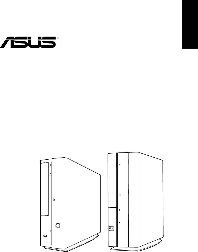
P-Series
ASUS PC (Desktop Barebone)
Installation manual
Download the latest manual from the ASUS website: www.asus.com
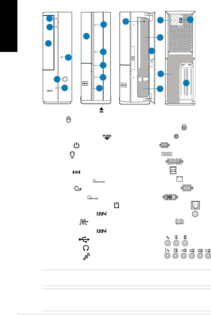
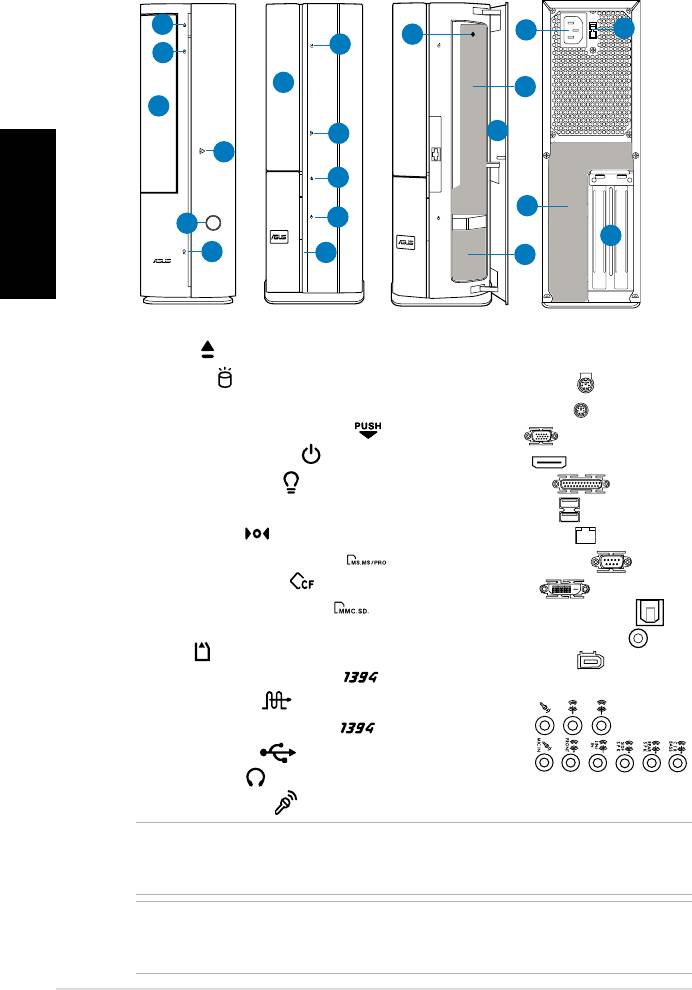
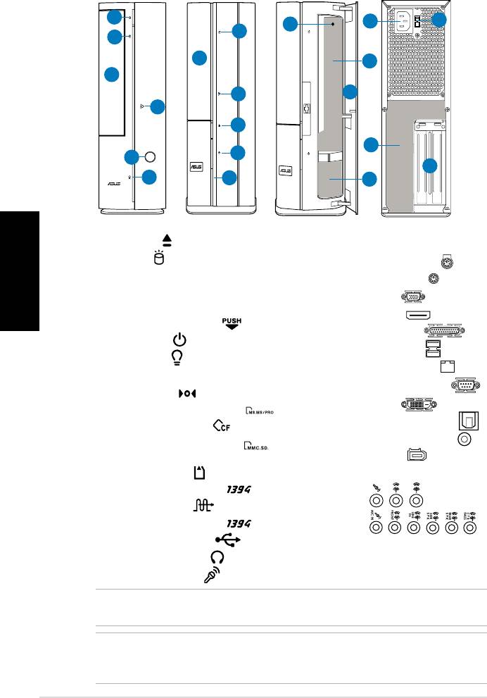
Front/Rear panel features
P1 Front (Close)
P2 Front (Close)
Front (Open)
Rear
English
1
11
12
8
2
2
3
9
3
4
7
4
1
13
5
5
14
6
6
10
1. Optical drive eject button ( )
11. Power connector
12.** Voltage selector switch
2. HDD LED (
)
3. Optical drive bay cover
13.* • PS/2 keyboard port (
)
4. Open the front panel cover (
)
• PS/2 mouse port (
)
• VGA port (
)
5. Power button ( )
• HDMI port (
)
6. Power LED (
)
• Parallel port (
)
7. Front panel cover
8. Reset button (
)
• USB 2.0 ports (
)
9.* • MS/MS Pro card slot (
)
• LAN (RJ-45) port (
)
• CF card slot (
)
• Serial (COM1) port (
)
• SD/MMC card slot (
)
• DVI-D port (
)
• MS/MS Pro/SD/MMC card slot (
)
• Optical S/PDIF Out port (
)
• 6-pin IEEE 1394a port (
)
• Coaxial S/PDIF Out port (
)
• S/PDIF In port (
)
• IEEE 1394a port (
)
10.* • 4-pin IEEE 1394a port (
)
•Audioportscongurations:
• USB 2.0 ports (
)
• 6-channel
• Headphone port (
)
• 8-channel
• Microphone port (
)
14. Expansion slot metal brackets
NOTE: *The front/rear panel slots/ports and their locations may vary, depending on the
model of your system. For detailed descriptions, refer to the system User Guide.
NOTE: **The system’s power supply unit has a 115V / 230V voltage selector switch
located beside the power connector. Use this switch to select the appropriate system
input voltage according to the voltage supply in your area.
2 Installation manual
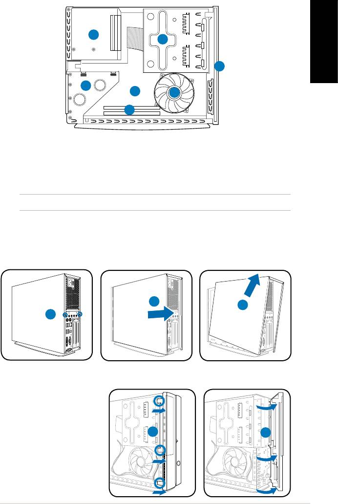
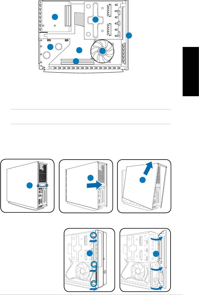
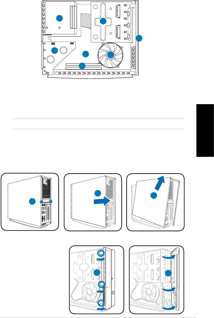
Internal components
3
2
English
1
4
5
7
6
1. Front panel cover
4. PCI card riser bracket (connected
2. 5.25-inch optical drive and
to the motherboard PCI slot)
3.5-inch hard disk drive cage
5. ASUS motherboard*
3. Power supply unit
6. DIMM sockets
7. CPU fan
NOTE: *Refer to the system User Guide for motherboard details.
Removing the cover
1. Remove the cover screws on the rear panel. Keep the screws for later use.
2. Pull the cover toward the rear panel.
3. Lift the cover, then set it aside.
2
3
Removing the front panel cover
1. Locate the front
panel cover hooks,
then lift them until
they disengage from
the chasis.
2. Swing the front panel
cover to the right,
remove it, and set it
aside.
3Installation manual
R
1
1
2
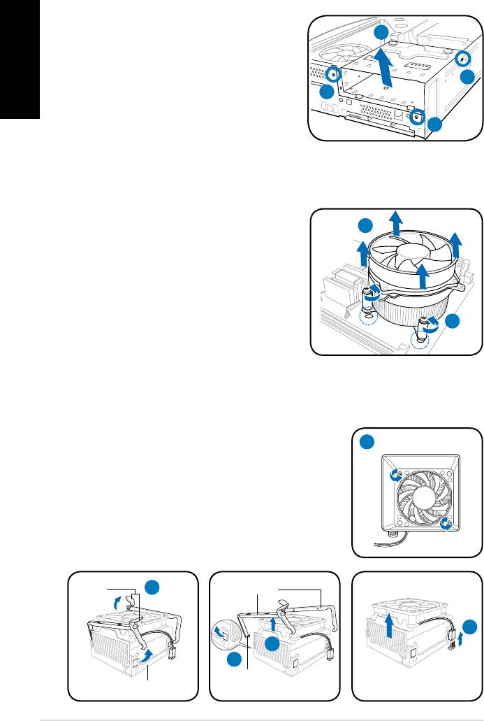
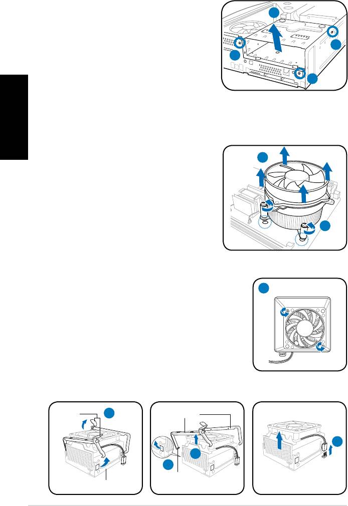
Removing the storage drive assembly
1. Lay the system on its side, then
English
locate and remove three storage
drive assembly screws.
2. Lift the storage drive assembly, then
set aside.
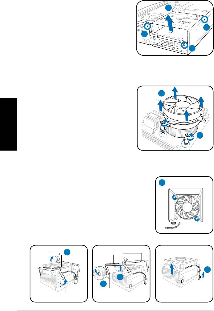
Removing the CPU fan and heatsink assembly
®
Removing an Intel
CPU fan and heatsink assembly
1. Disconnect the CPU fan cable from
the connector on the motherboard.
2. Loosen the four screws out of the
fan holes to disengage the fan
and heatsink assembly from the
motherboard.
3. Carefully remove the fan and
heatsink assembly, then set it aside.
Removing an AMD CPU fan and heatsink assembly
1. Remove two screws securing the blower to the CPU fan.
2. Carefully lift each locking lever and detach its end
from the hole of the retention module.
3. Release the hook of each metal clip from the hole
of the retention module.
4. Remove the metal clips from the side rail of the
fan and heatsink assembly.
5. Disconnect the CPU fan cable from the connector
on the motherboard, then remove the fan and
heatsink assembly.
4 Installation manual
2
1
1
1
3
2
1
Locking
2
Metal clip
levers
5
4
3
Hook
Retention module
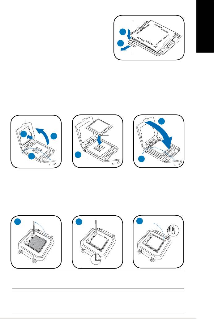
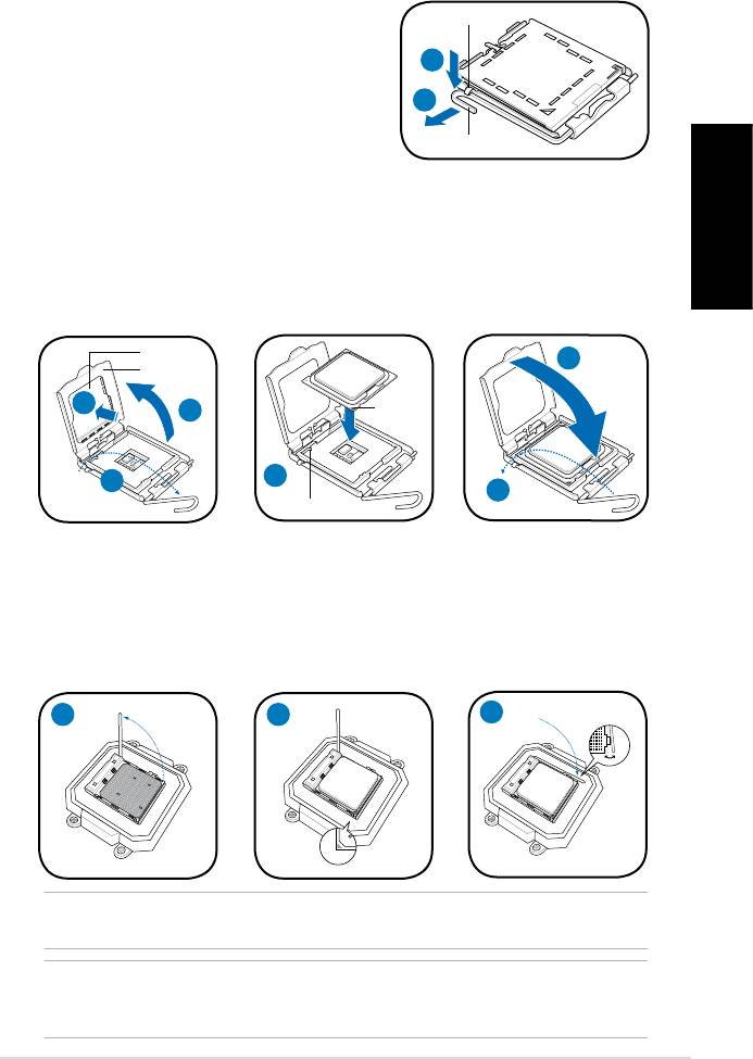
Installing a CPU
®
Installing an Intel
CPU in the LGA775 package
Retention tab
1. Locate the CPU socket on the motherboard.
2. Press the load lever with your thumb
2A
(2A), then move it to the left (2B) until it is
English
released from the retention tab.
2B
3. Lift the load lever in the direction of the
Load lever
arrow to a 135º angle.
4. Lifttheloadplatewithyourthumbandforengertoa100ºangle(4A),then
push the PnP cap from the load plate window to remove (4B).
5. Position the CPU over the socket, making sure that the gold triangle is on the
bottom-left corner of the socket. Fit the socket alignment key into the CPU
notch.
6. Close the load plate (6A), then push the load lever (6B) until it snaps into the
retention tab.
PnP cap
6A
Load plate
Gold
4B
4A
triangle
mark
5
3
6B
Alignment key
Installing an AMD CPU
1. Locate the CPU socket, then lift the socket lever to a 90º angle.
2. Install the CPU to the socket, making sure that the CPU corner with the gold
triangle matches the socket corner with a small triangle.
3. Push down the socket lever to secure the CPU.
1 2
3
®
NOTE: To reinstall an Intel
/ AMD CPU fan and heatsink assembly, follow the
instructions on page 4 in reverse order.
CAUTION: After you reinstall a fan and heatsink assembly, do not forget to connect
the CPU fan connector! Hardware monitoring error can occur if you fail to plug this
connector.
5Installation manual
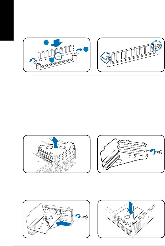
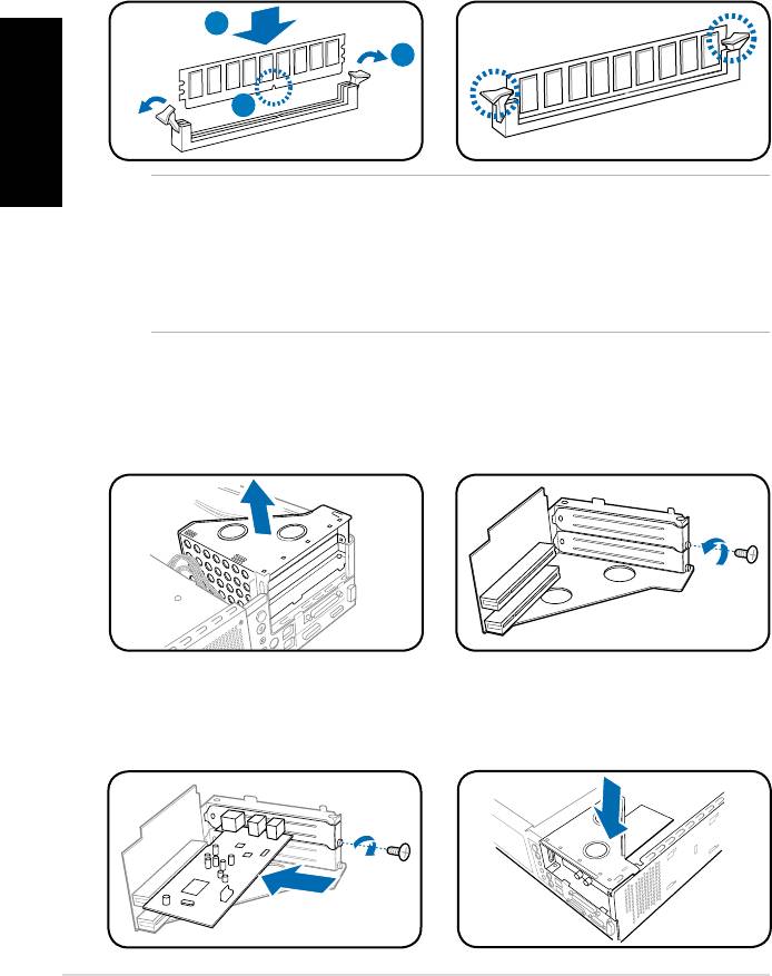
Installing a DIMM
1. Locate the DIMM sockets in the motherboard.
English
2. Unlock a DIMM socket by pressing the retaining clips outward.
3. Align a DIMM on the socket such that the notch on the DIMM matches the
break on the socket.
4. Push the DIMM to the socket until the retaining clips snap inward.
4
2
3
CAUTION:
• Unplug the power supply before adding or removing DIMMs. Failure to do so may
cause damage to the motherboard and/or components.
• ADDRDIMMiskeyedwithanotchsothatittsinonlyonedirection.Donotforce
a DIMM into a socket to avoid damaging the DIMM.
Installing an expansion card
1. Lift the PCI riser card assembly to
2. Remove the metal cover opposite
remove.
the slot that you intend to use.
3. Insert the card connector to the
4. Reinstall the PCI riser card
slot,thenpressthecardrmly
assembly. Make sure that the
untilittsinplace.Securethe
riser card connector sits properly
card with a screw.
on the motherboard PCI slot.
6 Installation manual
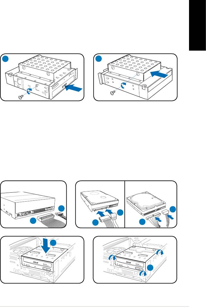
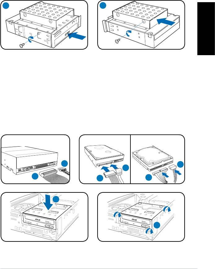
Installing optical and storage drives
1. Turn the storage drive assembly upside down with the 3.5-inch bay on top of
the 5.25-inch bay.
2. Insert the optical drive upside down to the 5.25-inch bay, then secure it with
two screws on both sides.
English
3. Turn the storage drive assembly, insert the hard disk drive upside down to the
3.5-inch bay, then secure it with two screws on both sides.
2
3
Reinstalling the storage drive assembly
1. Connect the IDE (1A) and power (1B) plugs to connectors at the back of the
optical drive.
2. Connect the SATA/IDE (2A) and power (2B) plugs to the connectors at the
back of the SATA/IDE hard disk drives.
3. Install the storage drive assembly to the chassis.
4. Secure the storage drive assembly with three screws.
SATA
IDE
1B
2B
2A
1A
2B
2A
7Installation manual
R
3
R
4
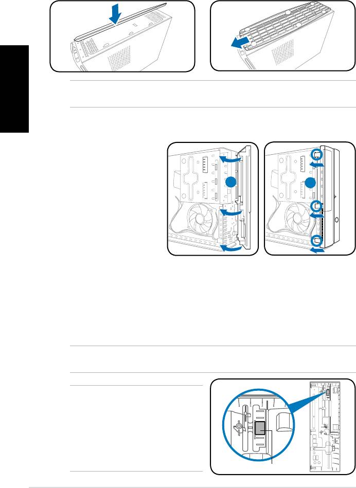
Installing the foot stand
1. Insert the foot stand hooks into
2. Pull the foot stand to the direction
English
the holes on the chassis.
of the arrow until the lock snaps
in place.
NOTE: To remove the foot stand, lift the lock, then slightly push the foot stand to the
direction of the rear panel until it disengages from the chassis.
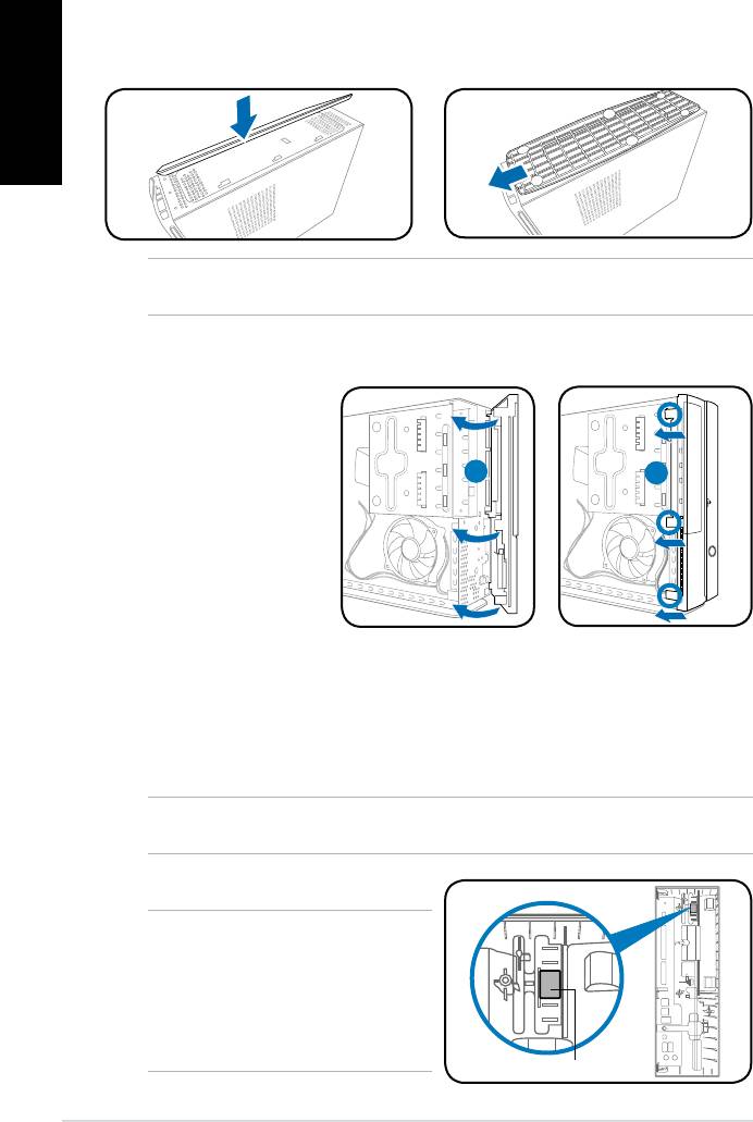
Reinstalling the front panel cover
Reinstalling the cover
1. Insertthecovertothechasis.Makesurethecovertabstthechasisrails.
2. Pushthecovertowardthefrontpaneluntilittsinplace.
3. Secure the cover with two screws you removed earlier.
NOTE: Refer to the pictures in the section “Removing the cover” on page 3 in reverse
order.
NOTE: For P2 model, if your optical
drive tray fails to eject when you press
the eject button, attach the provided
sticker to the location shown at the back
of the front panel cover. Make sure the
sticker aligns with the optical drive eject
button.
8 Installation manual
R
1. Insert the front panel
cover tabs to the holes
on the right side of the
chassis, then swing
1
2
the front panel cover to
the left.
2. Insert the front panel
cover hooks to the
chassis until the front
panelcovertsin
place.
Sticker
P-Série
ASUS PC (Système barebone)
Français
Manuel d’installation
Téléchargez les derniers manuels depuis le site web d’ASUS: www.asus.com
Caractéristiques de la façade/de l’arrière
P1 Façade (Fermé)
P2 Façade (Fermé)
Façade (Ouvert)
Arrière
1
11
12
8
2
2
3
9
3
4
7
4
Français
1
13
5
5
14
6
6
10
1. Bouton d’ejection du lecteur
11. Connecteur d’alimentation
optique ( )
12.** Interrupteur de sélection du voltage
2. LED HDD (
)
13.* • Port clavier PS/2 (
)
3. Capot de la baie du lecteur optique
• Port souris PS/2 (
)
4. Ouverture de la façade avant (
)
• Port VGA (
)
5. Bouton d’alimentation (
)
• Port HDMI (
)
6. LED d’alimentation (
)
• Port parallèle (
)
7. Façade
• Ports USB 2.0 (
)
8. Bouton Reset (
)
• Port LAN (RJ-45 (
)
9.* • Slot pour cartes MS/MS Pro (
)
• Port Série (COM1) (
)
• Slot pour cartes CF (
)
• Port DVI-D (
)
• Slot pour cartes SD/MMC (
)
• Port S/PDIF Out optique (
)
• Slot pour cartes MS/MS Pro/SD/
• Port S/PDIF Out coaxial (
)
MMC ( )
• Port IEEE 1394a (
)
• Port IEEE 1394a 6 broches (
)
•Congurationsdesportsaudio:
• Port S/PDIF In (
)
• 6 canaux
10.* •Port IEEE 1394a 4 broches (
)
• Ports USB 2.0 (
)
• 8 canaux
• Port Casque (
)
14. Supports métalliques des slots
• Port Microphone (
)
d’extension
NOTE: *Les ports/slots du panneau avant/arrière ainsi que leurs emplacements
peuvent varier selon le modèle de votre système. Pour une description détaillée,
reportez-vous au manuel de l’utilisateur de votre système.
NOTE:**L’alimentationdusystèmeestéquipéed’unsélecteurdetension115V/230V
situé près du connecteur d’alimentation. Utilisez cet interrupteur pour choisir la bonne
tension d’entrée en fonction des standards utilisés dans votre région.
2
Manuel d’installation
Composants internes
3
2
1
4
5
7
6
1. Façade
4. Bracket du PCI Card Riser
(connecté
Français
2. Bloc du lecteur optique 5.25’’ et
au slot PCI de la carte mère)
du lecteur de disque dur 3.5’’.
5. Carte mère ASUS*
6. Sockets DIMM
3. Alimentation
7. Système de refroidissement du CPU
NOTE: *Reportez-vous au manuel de l’utilisateur du système pour plus de détails sur
la carte mère.
Enlever le capot
1. Retirez les vis du panneau arrière. Conservez les vis pour un usage ultérieur.
2. Faites glisser le panneau latéral vers l’arrière.
3. Soulevez le capot, puis basculez-le.
2
3
Retirer le capot de la façade
1. Repérez les crochets
de la façade, et
soulevez-les jusqu’à ce
qu’ils se détachent du
châssis.
2. Faites pivoter la façade
vers la droite, retirez-la,
puis mettez-la de côté.
Manuel d’installation
3
R
1
1
2
Retirer l ’ensemble de stockage
1. Posez le système sur le côté, puis
localisez et retirez les trois vis de
l’ensemble de stockage.
2. Soulevez l’ensemble de stockage,
puis mettez-le de côté.
Français
Retirez un ensemble dissipateur-ventilateur
pour CPU
®
Retirez un ensemble dissipateur-ventilateur pour CPU Intel
1. Déconnectez le câble de ventilation du
CPU de son connecteur sur la carte
mère.
2. Retirez les quatre vis du ventilateur
pour désengager l’ensemble
dissipateur-ventilateur de la carte mère.
3. Retirez délicatement l’ensemble
dissipateur-ventilateur, puis mettez-le
de côté.
Retirez un ensemble dissipateur-ventilateur pour CPU AMD
1. Retirez les deux vis sécurisant les pâles du
ventilateur CPU. Mettez les pâles de côté
2. Levez avec précaution chaque levier de
verrouillage et détachez son extrémité des
ouvertures du module de rétention.
3. Désengagezlapattedexationdechaqueclip
métallique de l’ouverture du module de rétention.
4. Retirez les clips métalliques de leur rail latéral.
5. Déconnectez le câble de ventilation du CPU de son connecteur sur la carte
mère, puis retirez l’ensemble dissipateur-ventilateur.
4
Manuel d’installation
2
1
1
1
3
2
1
Levier de
2
Clip métallique
verrouillage
5
4
3
Pattedexation
Module de rétention
Installer un CPU
®
Installer un processeur Intel
au format LGA775
1. Localisez le socket du CPU sur la carte mère.
Loquet de rétention
2. Pressez le levier avec votre pouce (2A) et
glissez-le vers la gauche (2B) jusqu’à ce
2A
qu’il soit libéré du loquet de rétention.
2B
3. Levezlelevierdansladirectiondelaèche
à un angle de 135º.
Levier
4. Levez la plaque avec votre pouce à un angle
de 100°(4A), puis poussez le couvercle PnP de la plaque pour l’enlever (4B).
5. Placez le CPU au dessus du socket, en vous assurant que le triangle doré
soit dans le coin inférieur gauche du socket. La clef d’alignement du socket
Français
doit correspondre avec l’encoche du CPU.
6. Refermez la plaque (6A), puis poussez le levier (6B) jusqu’à ce qu’il soit
accroché par le loquet de rétention.
Plaque de
protection
6A
Plaque
Marque
4B
4A
triangulaire
dorée
5
3
6B
Clef d’alignement
Installer le AMD CPU
1. Repérez le socket du CPU, puis soulever le levier du socket de 90°.
2. Placez le CPU sur le socket, en vous assurant que le triangle doré sur le
CPU est installé sur le triangle du socket.
3. AbaissezlelevierdusocketandesécuriserleCPU.
1 2
3
®
NOTE: Pour réinstaller un ensemble dissipateur-ventilateur pour CPU Intel
/ AMD,
suivez les instructions de la page 4 dans l’ordre inverse.
CAUTION: Après avoir réinstaller un ensemble dissipateur-ventilateur, n’oubliez pas de
connectez le connecteur de ventilation du CPU au connecteur CPU_Fan de la carte mère !
Des erreurs de monitoring matériel pourraient survenir si vous ne branchez pas ce connecteur.
Manuel d’installation
5
Installer un module DIMM
1. Localisez les sockets DIMM de la carte mère.
2. Déverrouillez un socket DIMM en pressant sur les clips de rétention vers l’extérieur.
3. Alignez un module DIMM sur le socket de sorte que l’encoche sur la DIMM
corresponde à l’ergot du socket.
4. Enfoncez le module DIMM dans le socket jusqu’à ce que les clips de
rétention se referment.
4
Français
2
3
ATTENTION:
• Débranchez la source d’alimentation avant d’ajouter ou de retirer des modules
DIMMs. Ne pas le faire peut endommager la carte mère et/ou les composants.
• Un module DDR DIMM est verrouillé par une encoche, de sorte qu’il ne peut
entrer dans le socket que dans un seul sens. NE FORCEZ pas sur un module
pour le faire entrer dans son socket pour ne pas l’endommager.
Installer une carte d’extension
1. Soulevez l’ensemble PCI Riser
2. Retirez la protection métallique
Card pour le retirez du châssis.
faisant face au slot que vous
désirez utiliser.
3. Insérez le connecteur de la carte
4. Réinstallez l’ensemble PCI Riser Card.
dans le slot et pressez jusqu’à
Assurez-vous que le connecteur de
ce que la carte soit en place.
la riser card soit bien connecté au slot
Sécurisez la carte avec une vis.
PCI de la carte mère.
6
Manuel d’installation
Installer un lecteur optique ou de stockage
1. Placez l’ensemble de stockage de façon à ce que la baie 3.5” soit au dessus
de la baie 5.25”.
2. Insérez le lecteur optique dans la baie 5.25”, puis sécurisez-le avec deux vis
de chaque côté.
3. Insérez le disque dur dans la baie 3.5”, puis sécurisez-le avec deux vis de
chaque côté.
2
3
Français
Réinstaller l’ensemble de stockage
1. Connectez les prises IDE (1A) et d’alimentation (1B) aux connecteurs
localisés à l’arrière du lecteur optique.
2. Connectez les prises SATA/IDE (2A) et d’alimentation (2B) aux connecteurs
localisés à l’arrière des disques durs SATA/IDE.
3. Installez l’ensemble de stockage sur le châssis.
4. Sécurisez l’ensemble de stockage avec trois vis.
SATA
IDE
1B
2B
2A
1A
2B
2A
Manuel d’installation
7
R
3
R
4
Installer le pied de support
1. Insérez le support vertical dans
2. Tirez le support vertical dans la
les ouvertres pourvues à cet effet
directiondelaêchejusqu’àce
sur le châssis.
qu’il soit bien en place.
Français
NOTE: Pour retirez le support vertical, levez le verrou, puis poussez légèrement le support
vertical dans la direction du panneau arrière jusqu’à ce qu’il se désengage du châssis.
Réinstaller le capot de la façade
Réinstaller le panneau
1. Installer le panneau sur le châssis en vous assurant que les onglets du
panneau soient bien alignés sur les rails du châssis.
2. Poussez le panneau vers l’avant jusqu’à ce qu’il soit bien en place.
3. Sécurisez le capot avec les deux vis, retirées précédemment.
NOTE: Reportez-vous aux images de la section “Retirer la façade” à la page 3 dans
l’ordre inverse.
NOTE: Pour le modèle P2, si votre
lecteur optique ne parvient pas à éjecter
un disque lors de la pression du bouton
d’éjection, placez l’autocollant fourni
à l’emplacement illustré sur l’image
ci-contre. Assurez-vous que l’autocollant
est bien aligné sur le bouton d’éjection
du lecteur optique.
8
Manuel d’installation
R
1. Insérez les clapets
de la façade dans les
ouvertures situées sur
le côté droit du châssis,
1
2
puis faits pivoter la
façade vers la gauche.
2. Insérez les crochets du
capot de la façade dans
les onglets du châssis
jusqu’à ce que le capot
soit bien en place.
Autocollant
P-Serie
ASUS PC (Desktop Barebone)
Installationshandbuch
Deutsch
Die neueste Version des Handbuchs nden Sie auf der ASUS-Website: www.asus.com
Frontseite/Rückseite
P1-Vorderseite
P2-Vorderseite
Vorderseite
Rückseite
(geschlossen)
(geschlossen)
(Offen)
1
11
12
8
2
2
3
9
3
4
7
4
1
13
5
5
14
6
6
10
1. Auswurftaste des optischen
11. Stromanschluss
Deutsch
Laufwerkes ( )
12.** Spannungsauswahlschalter
2. HDD-LED (
)
13.* • PS/2-Tastaturanschluss (
)
3. Schubladenabdeckung des
• PS/2-Mausanschluss (
)
optischen Laufwerkes
• VGA-Anschluss (
)
4. Entfernen Sie die
• HDMI-Anschluss (
)
Vorderseitenabdeckung ( )
• Paralleler Anschluss (
)
5. Stromschalter (
)
• USB 2.0-Anschlüsse (
)
6. Betriebs-LED (
)
• LAN (RJ-45)-Anschluss (
)
7. Fronttafelabdeckung
• Serieller (COM1) Anschluss (
)
8. Reset-Schalter (
)
• DVI-D-Ausgang (
)
9.* • MS/MS Pro-Kartensteckplatz (
)
• Optischer S/PDIF-Ausgang (
)
• CF-Kartensteckplatz (
)
• Koaxialer S/PDIF-Ausgang (
)
• SD/MMC-Kartensteckplatz (
)
• MS/MS Pro/SD/MMC-
• IEEE-1394a-Port (
)
Kartensteckplatz ( )
•Audioanschlusseinstellungen:
• 6-Pin-IEEE-1394a-Port (
)
• 6-Kanal
• S/PDIF-Eingang (
)
10.* • 4-Pin-IEEE-1394a-Port (
)
• 8-Kanal
• USB 2.0-Anschlüsse (
)
14. Metallene
• Kopfhöreranschluss (
)
Erweiterungssteckplatzklammern
• Mikrofonanschluss (
)
HINWEIS: *Die Anschlüsse an Vorder- und Rückseite und ihre Position können je nach
Modellvariieren.GenauereBeschreibungenndenSieimBenutzerhandbuchdesSystems.
HINWEIS: **Das Netzteil ist mit einem 115V/230V-Spannungsschalter neben dem Stromanschluss
ausgestattet. Verwenden Sie diesen Schalter, um die passende Systemeingangsspannung
entsprechend Ihrem Stromversorgungssystem in Ihrer Region auszuwählen.
2 Installationshandbuch
Interne Komponenten
3
2
1
4
5
7
6
1. Fronttafelabdeckung
4. Befestigungsklammer für PCI-
Karten (mit dem PCI-Steckplatz
2. Halterung für optisches
des Motherboards verbunden)
Laufwerk 5.25-Zoll und 3.5 Zoll
5. ASUS-Motherboard*
Festplattenlaufwerk
6. DIMM-Steckplätze
3. Netzteil
7. Prozessorlüfter
HINWEIS:*DetailszumMotherboardndenSieimBenutzerhandbuchdesSystems.
Entfernen der Abdeckung
Deutsch
1. Entfernen Sie die Schrauben der Abdeckung an der Rückseite. Die
Schrauben für spätere Wiederverwendung gut aufheben.
2. Ziehen Sie die Abdeckung nach hinten.
3. Heben Sie die Abdeckung und legen sie zur Seite.
2
3
Entfernen der Frontabdeckung
1. Suchen Sie
die Haken der
Vorderseitenabdeckung
und heben Sie sie
an, bis sie sich vom
Gehäuse lösen.
2. Drehen Sie die
Vordeseitenabdeckung
nach rechts und
entfernen Sie sie.
3Installationshandbuch
R
1
1
2
Entfernen der Frontabdeckung
1. Haken Sie die Haken der
Frontabdeckung aus.
2. Vorsichtig die Frontabdeckung
entfernen und beiseite stellen.
Entfernen einer CPU-Lüfter-Kühlkörpereinheit
®
Entfernen einer Intel
CPU-Lüfter-Kühlkörpereinheit
1. Entfernen Sie das CPU-Lüfterkabel
vom Anschluss am Motherboard.
2. Lösen Sie die vier Schrauben, um
Deutsch
die Lüfter-/Kühlkörpereinheit vom
Motherboard entfernen zu können.
3. Entfernen Sie die Einheit vorsichtig
und legen Sie sie beiseite.
Entfernen einer AMD CPU-Lüfter-Kühlkörpereinheit
1. Entfernen Sie die zwei Schrauben, die das Gebläse am CPU-Lüfter befestigen.
2. Heben Sie vorsichtig die Halteriegel an und lösen
Sie deren Enden von den jeweiligen Löchern am
Befestigungsmodul.
3. Lösen Sie die Haken der Metallklammern aus den
Löchern am Befestigungsmodul.
4. Entfernen Sie die Metallklammern von den Seiten
der Lüftereinheit.
5. Ziehen Sie das CPU-Lüfterkabel vom Anschluss
am Motherboard ab und entfernen Sie dann die Lüfter-/Kühlkörperheinheit.
4 Installationshandbuch
2
1
1
1
3
2
1
Halteriegel
2
Metallklammer
5
4
3
Haken
Befestigungsmodul


