Asus G1-P5G43: instruction
Class: Household, kitchen appliances, electronics and equipment
Type: Computer
Manual for Asus G1-P5G43
Table of contents
- Installation manual
- Internal components Removing the side cover and front panel assembly
- Installing a CPU Installing an Intel CPU Installing an AMD CPU
- Installing the CPU fan and heatsink assembly Installing an Intel CPU heatsink and fan Installing an AMD CPU heatsink and fan
- Installing a DIMM Installing an expansion card
- Installing storage drives Optical drive Hard disk drive
- Reinstalling the front panel assembly and side cover
English
G-Series
ASUS PC (Desktop Barebone)
Installation manual
Download the latest manual from the ASUS website at http://support.asus.com.
Book G1.indb 1 9/1/09 6:10:25 PM
English
2
Installation manual
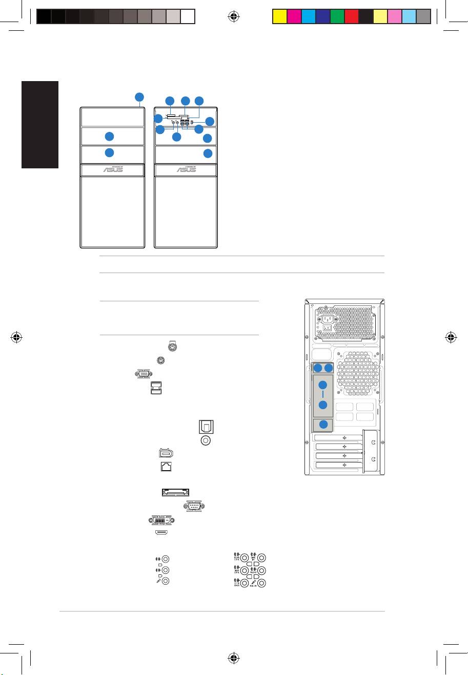
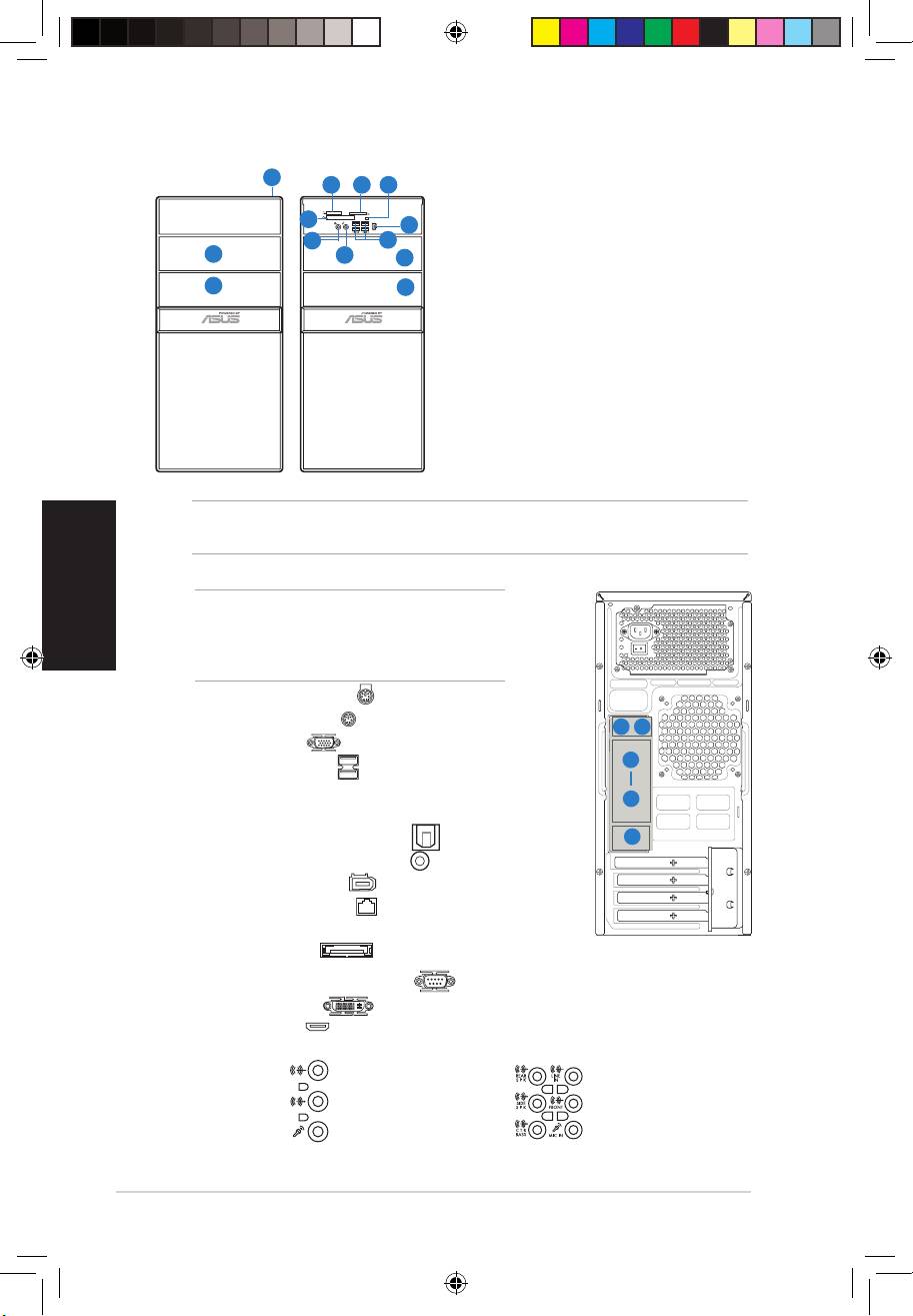
Front panel features
1
54
6
1. Power button
2. Optical drive bay cover
7
11
8
10
3. 5.25-inch drive bay cover
2
9
2
®
4. MemoryStick
/Memory Stick Pro™
card slot
3
3
5. Secure Digital™/Multimedia Card slot
6. Card reader LED
®
7. CompactFlash
/Microdrive™ card slot
8. Headphone port
9. Microphone port
10. USB 2.0 ports*
11. IEEE1394a port*
NOTE: * Some models may have only two USB 2.0 ports and/or no IEEE 1394a port.
Rear panel features
NOTE: The rear panel ports and their locations may
vary, depending on the model of your system. For
detailed descriptions, refer to the system User Guide.
1. PS/2 keyboard port ( )
2. PS/2 mouse port ( )
3. VGA port ( )
4. USB 2.0 ports ( )
(some models may have four rear USB
2.0 ports)
5. One of the following ports:
• Optical S/PDIF Out port ( )
• Coaxial S/PDIF Out port ( )
6. IEEE 1394a port ( )
(some models only)
7. LAN (RJ-45) port ( )
8. One of the following ports:
• E-SATA port ( )
• Serial (COM1) port ( )
• DVI port ( )
• HDMI port ( )
9. Oneofthefollowingaudioportscongurations:
• 6-channel • 8-channel
RefertothecongurationtableintheUserGuidefordetails.
HDMI
SPDIF OUT
DVI
1 2
3
8
9
Book G1.indb 2 9/1/09 6:10:32 PM
English
Installation manual
3
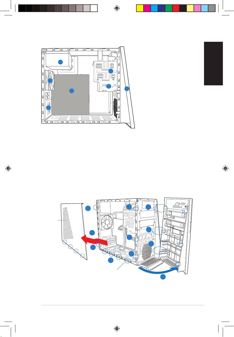
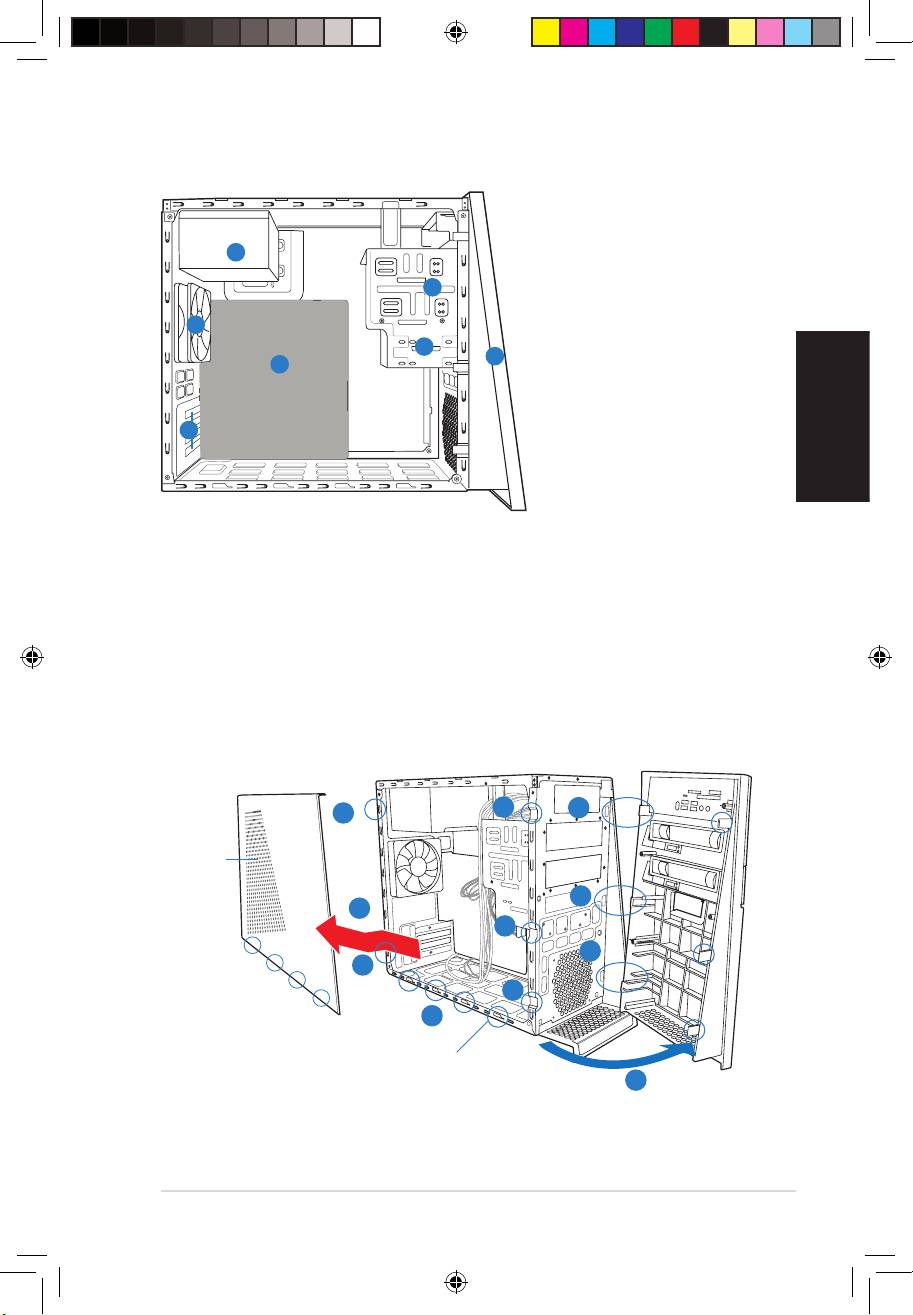
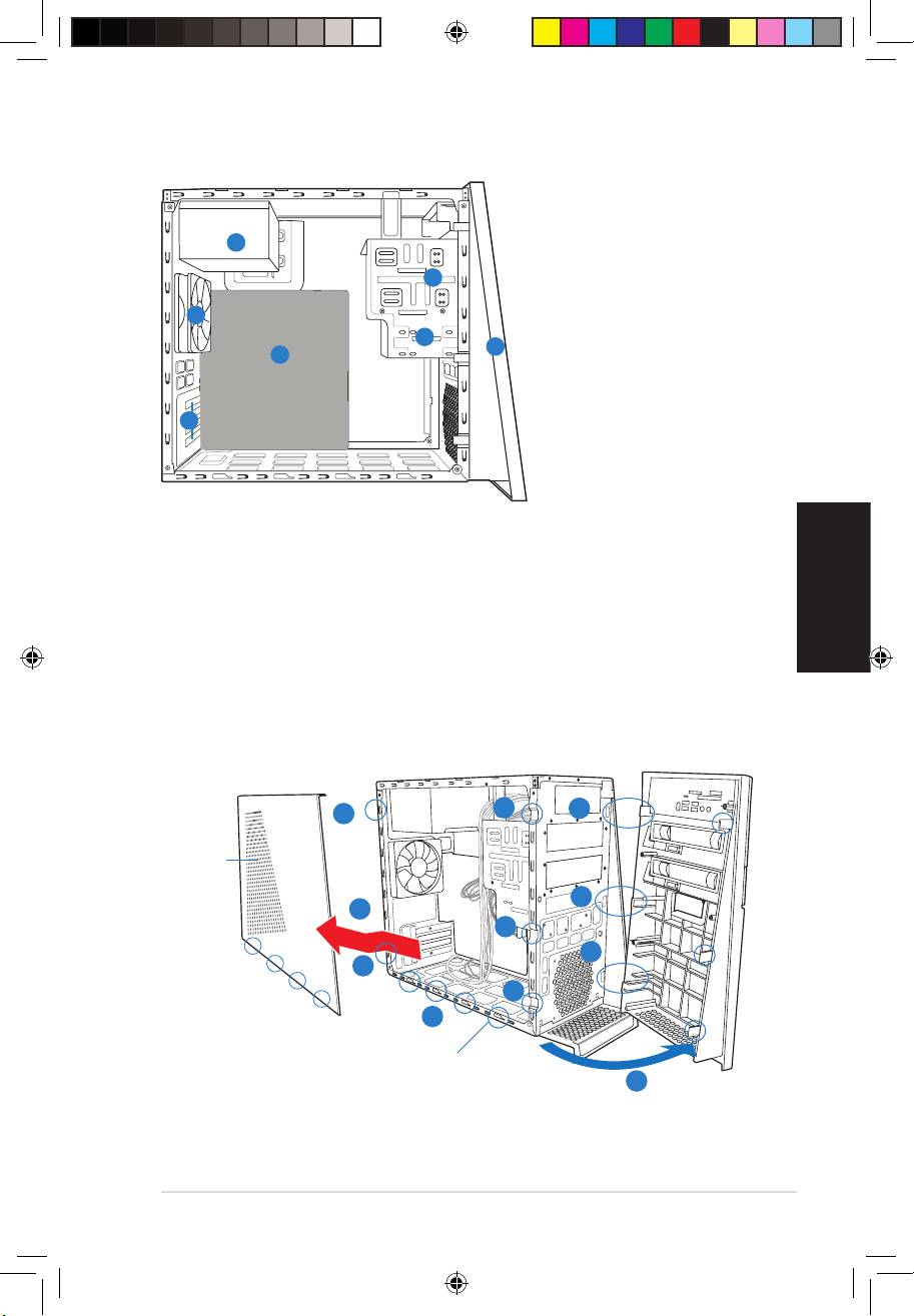
Internal components
1. Front panel cover
2. 5.25-inch optical drive bays
4
3. Hard disk drive bay
2
4. Power supply unit
5. ASUS motherboard
6
6. Chassis fan
3
7. Expansion slot metal brackets
1
5
7
Removing the side cover and front panel assembly
1. Remove the cover screws on the rear panel.
2. Pull the side cover toward the rear panel until its hooks disengage from the chassis tab
holes. Set the side cover aside.
3. Locate the front panel assembly hooks, then lift them until they disengage from the
chassis.
4. Swing the front panel assembly to the right, until the hinge-like tabs on the right side of
the assembly are exposed.
5. Remove the front panel assembly, then set aside.
3
4
1
Air duct
4
2
3
4
1
3
2
Chassis tab holes
4
Book G1.indb 3 9/1/09 6:10:34 PM
English
4
Installation manual
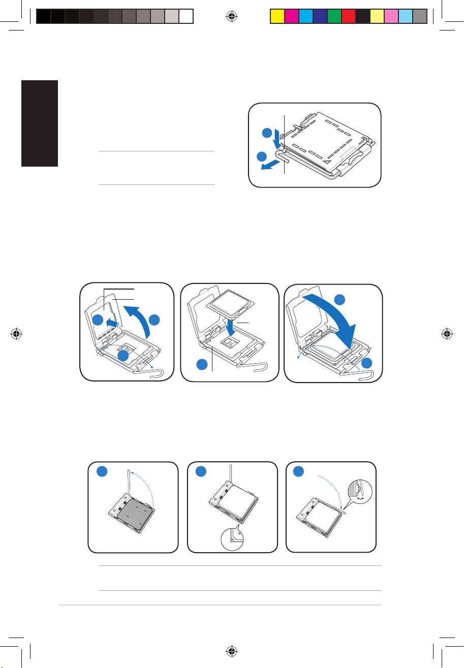
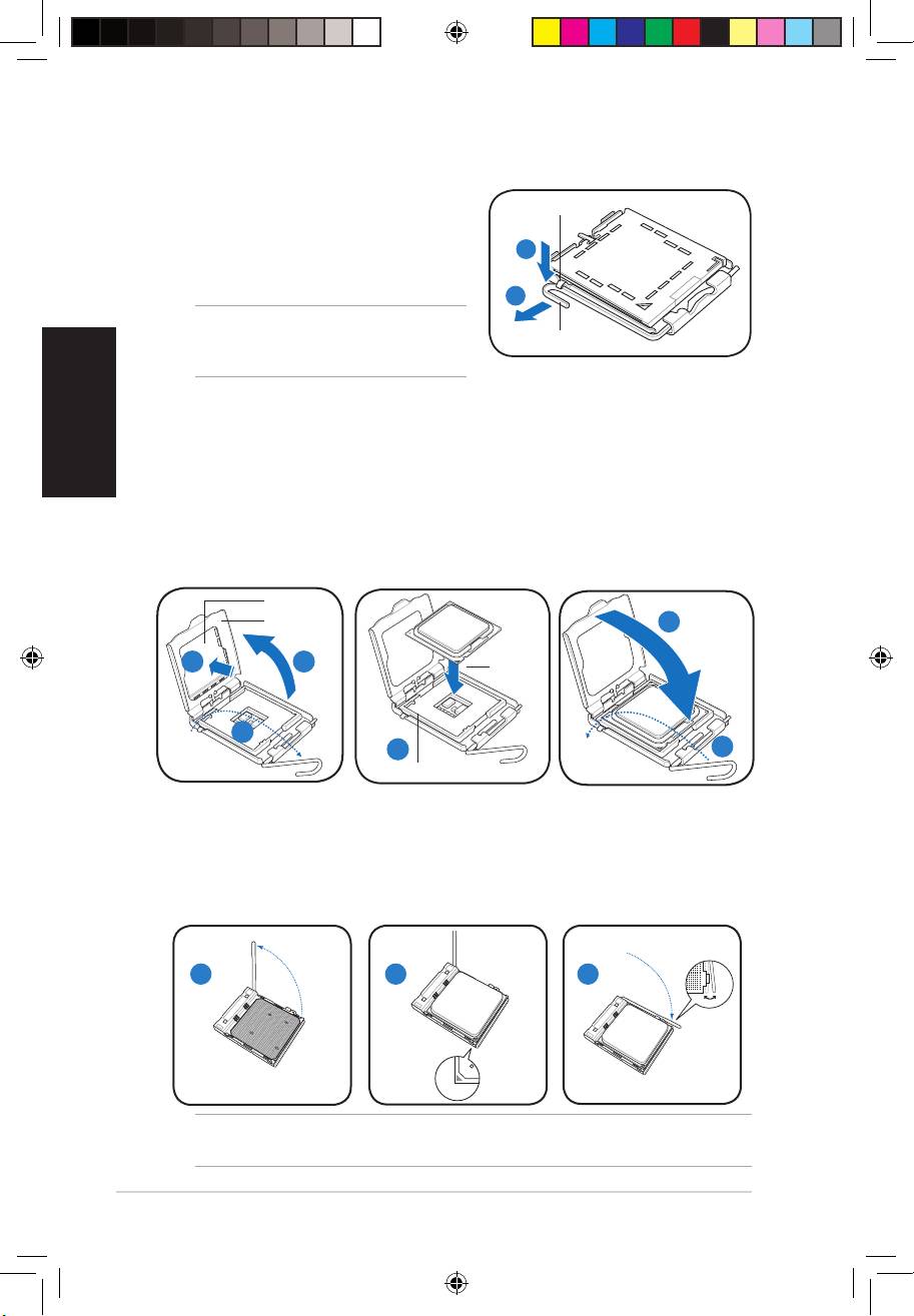
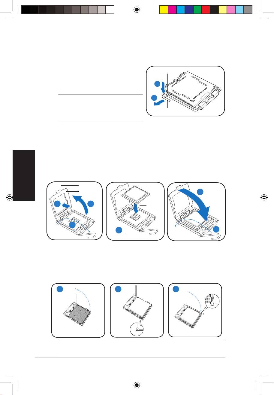
Installing a CPU
Installing an Intel CPU
1. Locate the CPU socket on the motherboard.
Retention tab
2. Press the load lever with your thumb (2A),
then move it to the left (2B) until it is released
2A
from the retention tab.
2B
CAUTION! To prevent damage to the
socket pins, do not remove the PnP cap
unless you are installing a CPU.
Load lever
3. Lift the load lever in the direction of the arrow to a 135º angle.
4. Lifttheloadplatewithyourthumbandforengertoa100ºangle(4A),thenpushthe
PnP cap from the load plate window to remove (4B).
5. Position the CPU over the socket, making sure that the gold triangle is on the
bottom-left corner of the socket. Fit the socket alignment key into the CPU notch.
6. Close the load plate (6A), then push the load lever (6B) until it snaps into the retention
tab.
PnP cap
Load plate
6A
Gold
4B 4A
triangle
mark
3
5
6B
Alignment key
Installing an AMD CPU
1. Locate the CPU socket, then lift the socket lever to a 90º angle.
2. Install the CPU to the socket, making sure that the CPU corner with the gold triangle
matches the socket corner with a small triangle.
3. Push down the socket lever to secure the CPU.
1 2 3
CAUTION: Incorrect installation of the CPU into the socket may bend the pins and severely
damage the CPU!
Book G1.indb 4 9/1/09 6:10:38 PM
English
Installation manual
5
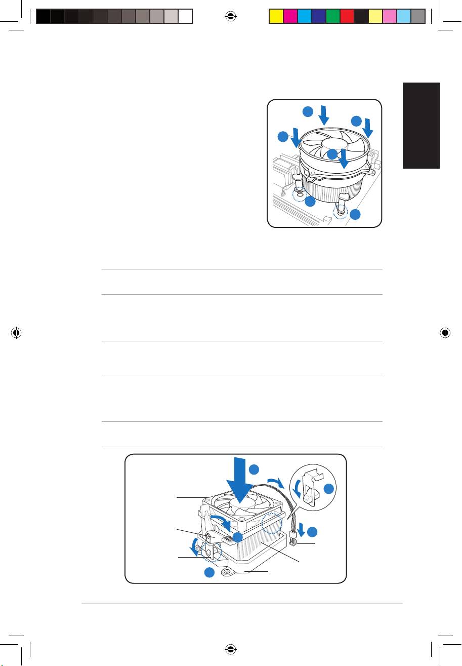
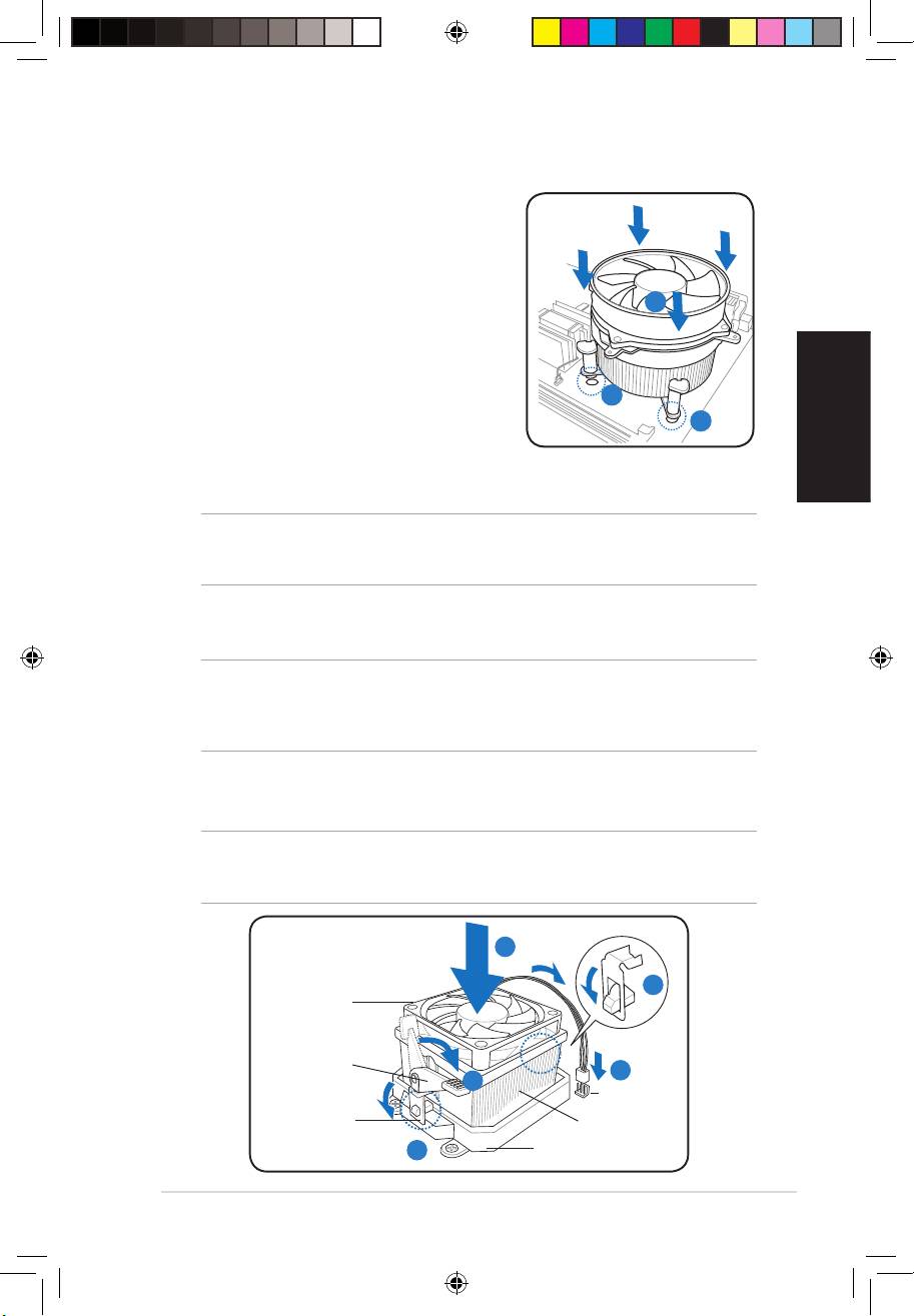
Installing the CPU fan and heatsink assembly
Installing an Intel CPU heatsink and fan
A
1. Place the heatsink on top of the installed CPU,
B
making sure that the four fasteners match the
holes on the motherboard.
B
2. Push down two fasteners at a time in a diagonal
A
sequence to secure the heatsink and fan assembly
in place.
3. When the fan and heatsink assembly is in place,
connect the CPU fan cable to the connector on the
motherboard.
1
1
Installing an AMD CPU heatsink and fan
1. Place the heatsink on top of the installed CPU.
IMPORTANT.Makesurethatthefanandheatsinkassemblyperfectlytstheretentionmechanism
module base; otherwise you can not lock the retention bracket.
2. Attach one end of the retention bracket to the retention module base.
3. Attach the other end of the retention bracket (near the retention bracket lock) to the
retention module base until it clicks in place.
NOTE. Your boxed CPU should come with installation instructions for the CPU, fan/heatsink assembly,
and the retention mechanism. If the instructions in this section do not match the CPU documentation,
follow the latter.
4. Push down the retention bracket lock on the retention mechanism to secure the fan
and heatsink to the module retention module base.
5. Connect the CPU fan cable to the connector on the motherboard.
CAUTION. Do not forget to connect the CPU fan connector! Hardware monitoring error can occur if
you fail to plug this connector.
1
2
CPU fan
Retention
bracket lock
5
4
CPU fan
connector
Retention bracket
CPU heatsink
3
Retention module base
Book G1.indb 5 9/1/09 6:10:39 PM
English
6
Installation manual
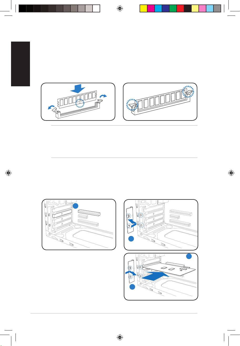
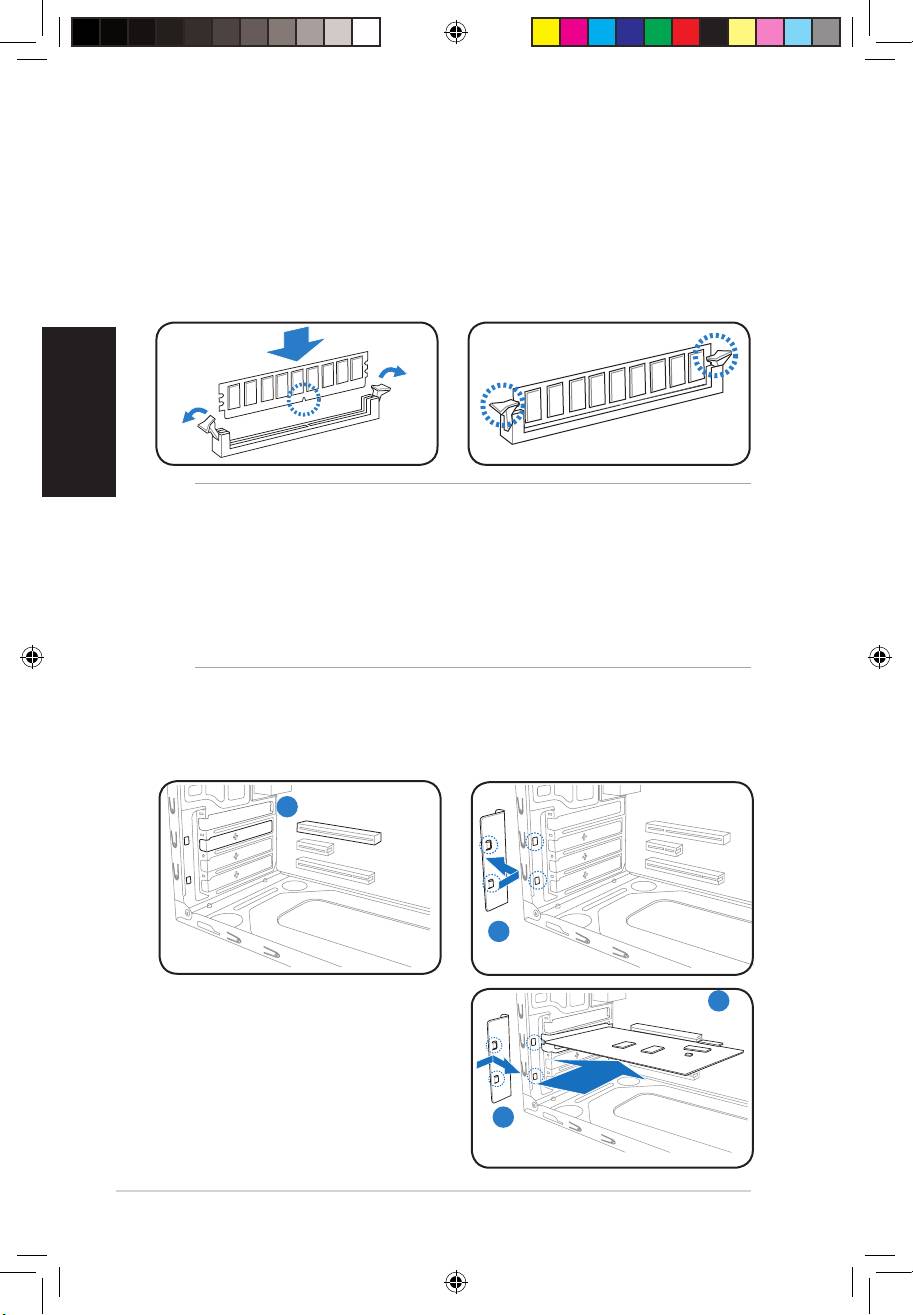
Installing a DIMM
1. Locate the DIMM sockets in the motherboard.
2. Unlock a DIMM socket by pressing the retaining clips outward.
3. Align a DIMM on the socket such that the notch on the DIMM matches the break on the
socket.
4. Push the DIMM to the socket until the retaining clips snap inward.
CAUTION:
• Unplug the power supply before adding or removing DIMMs. Failure to do so may
cause damage to the motherboard and/or components.
• ADDR2/DDR3DIMMiskeyedwithanotchsothatittsinonlyonedirection.
Do not force a DIMM into a socket to avoid damaging the DIMM.
Installing an expansion card
2. Remove the metal bracket lock.1. Remove the metal cover opposite the
slot that you intend to use.
1
2
3
3. Insert the card connector to the slot,
thenpressthecardrmlyuntilittsin
place.
4. Replace the metal bracket lock.
4
Book G1.indb 6 9/1/09 6:10:41 PM
English
Installation manual
7
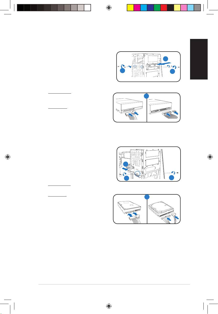
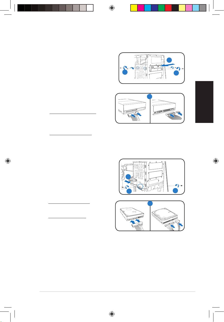
Installing storage drives
Optical drive
1. Place the chassis upright, then remove the
upper 5.25” drive bay metal plate cover.
2
2. Insert the optical drive to the bay, then
carefully push the drive until its screw holes
3
3
align with the holes on the bay.
3. Secure the optical drive with two screws on
both sides of the bay.
4. For SATA ODD: Connect the SATA
signal and power plugs to the
SATA IDE
4
connectors at the back of the drive.
For IDE ODD: Connect the IDE and power
plugs to the connectors at the back of the
drive.
Hard disk drive
1. Locate the 3.5-inch hard disk drive bay.
2. Insert the hard disk drive to the
3.5-inch hard disk drive bay, then carefully
push the drive until its screw holes align
2
with the holes on the bracket.
3. Secure the hard disk drive with two screws
on both sides of the bay.
3
3
4. For SATA HDD: Connect the SATA signal
and power plugs to the connectors at the back of the drive.
For IDE HDD: Connect the IDE and power
SATA IDE
4
plugs to the connectors at the back of the
drive.
Book G1.indb 7 9/1/09 6:10:44 PM
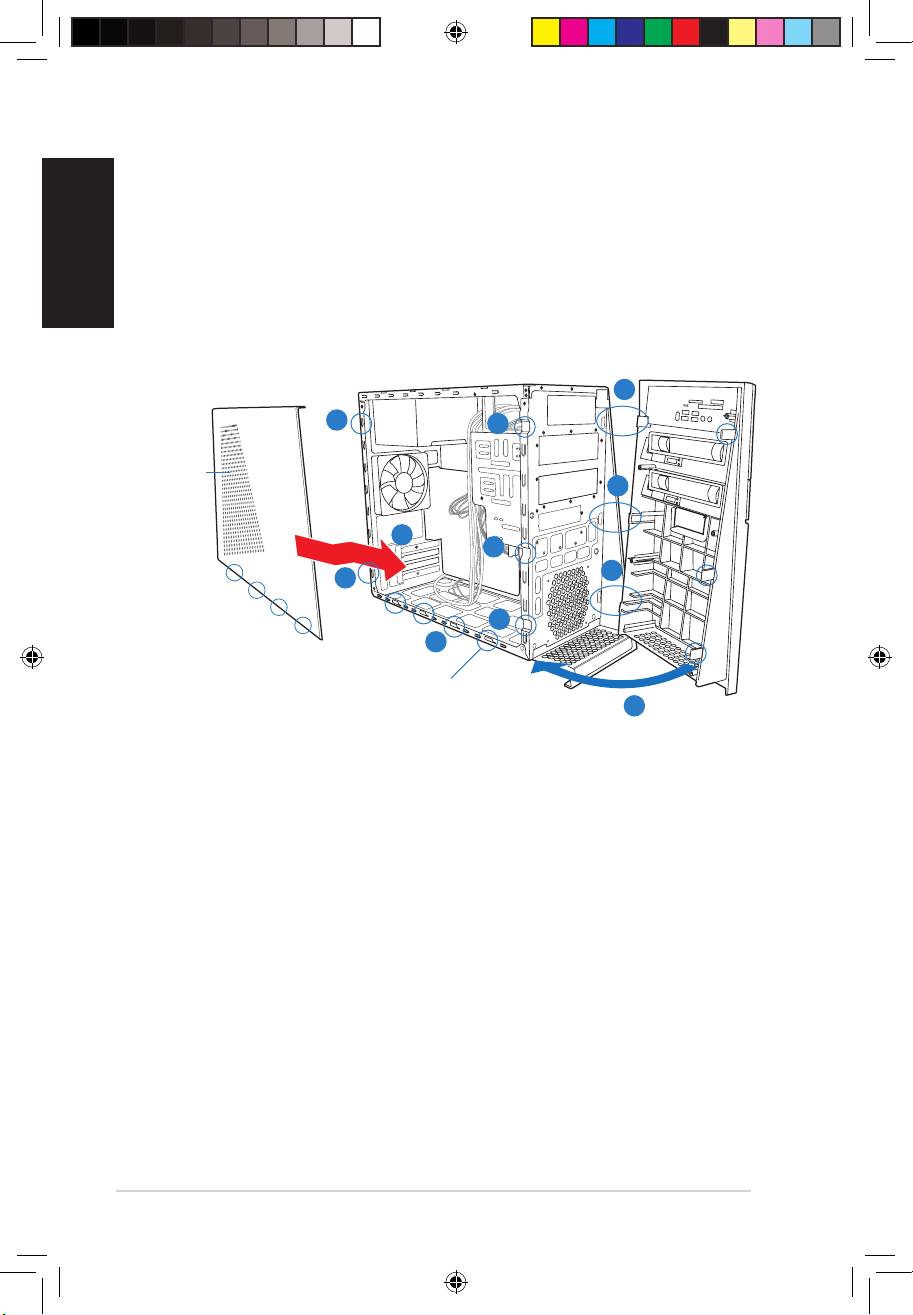
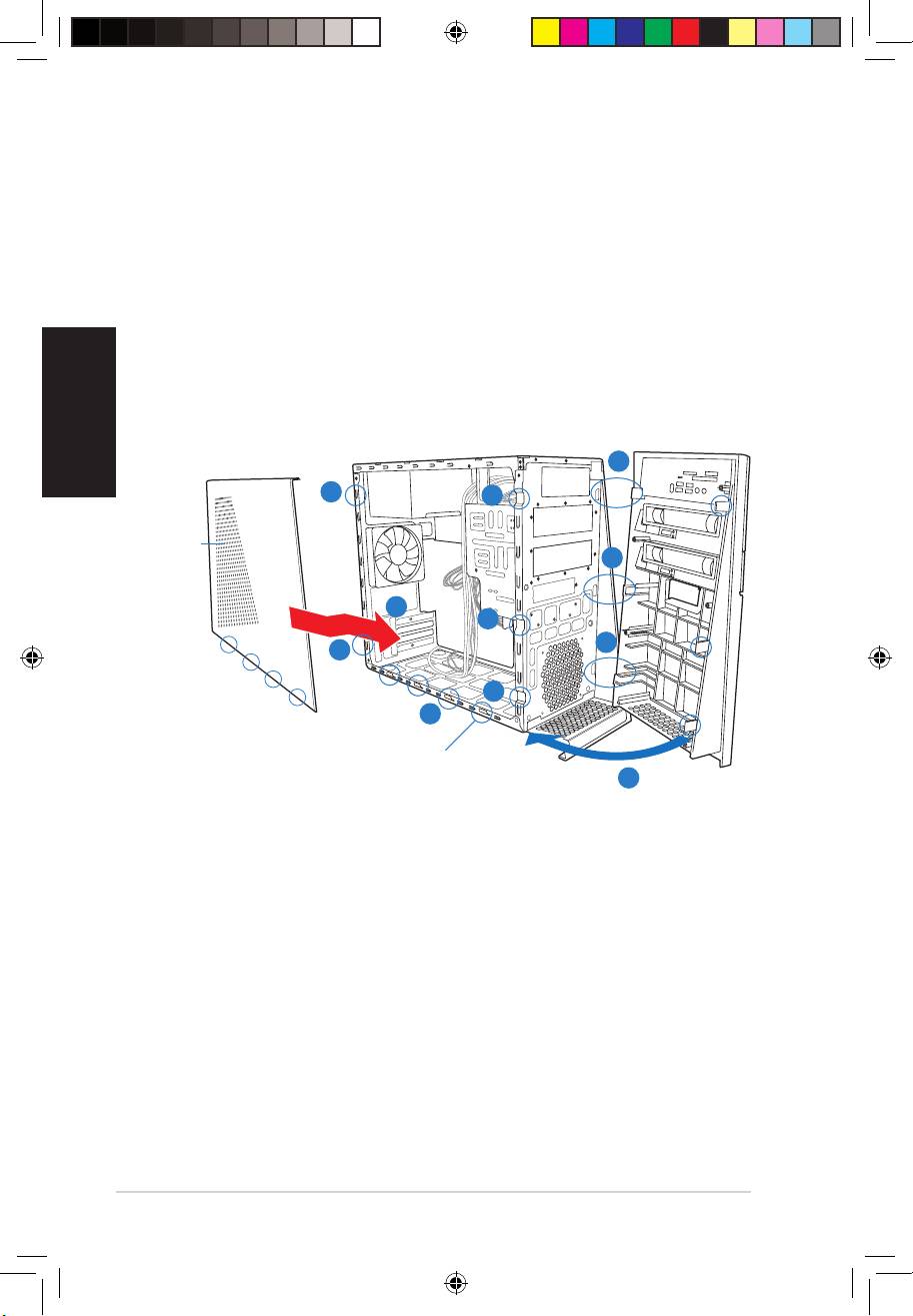
Reinstalling the front panel assembly and side cover
To reinstall the front panel assembly and side cover:
English
1. Insert the front panel assembly hinge-like tabs to the holes on the right side of the
chassis.
2. Swing the front panel assembly to the left, then insert the hooks to the chassis until the
frontpanelassemblytsinplace.
3. Insert the six side cover hooks into the chassis tab holes .
4. Pushthesidecovertothedirectionofthefrontpaneluntilittsinplace.
5. Secure the cover with two screws you removed earlier.
1
5
2
Air duct
1
4
2
1
5
2
3
Chassis tab holes
2
8
Installation manual
Book G1.indb 8 9/1/09 6:10:46 PM
G-Série
ASUS PC (Système barebone)
Français
Manuel d’installation
Download the latest manual from the ASUS website at http://support.asus.com.
Book G1.indb 1 9/1/09 6:10:48 PM

Français
2
Manuel d’installation
Caractéristiques de la façade
NOTE: ** Certains modèles peuvent intégrer deux ports USB 2.0 additionnels et/ou un port IEEE
1394a.
Caractéristiques de l’arrière
NOTE: Les ports du panneau arrière ainsi que leur emplacement peuvent varier selon votre
système. Pour une description détaillée, reportez-vous au manuel de l’utilisateur de votre système.
1. Port clavier PS/2 ( )
2. Port souris PS/2 ( )
3. Port VGA ( )
4. Ports USB 2.0 ( )
(certains modèles peuvent intégrer
quatre ports USB 2.0)
5. Un des ports suivants:
• Port S/PDIF Out optique ( )
• Port S/PDIF Out coaxial ( )
6. Port IEEE 1394a ( )
(uniquement sur certains modèles)
7. Port LAN (RJ-45) ( )
8. Un des ports suivants:
• Port E-SATA ( )
• Port Série (COM1) ( )
• Port DVI ( )
• Port HDMI ( )
9. Unedescongurationsdeportsaudiosuivantes:
• 6 canaux • 8 canaux
Reportez-vousautableaudecongurationcontenudanslemanueldel’utilisateurpour
plus de détails.
HDMI
SPDIF OUT
DVI
1. Bouton d’alimentation
1
54
6
2. Cache pour baies optique
7
3. Cache pour baies 5.25”
11
8
10
4. Slot pour cartes mémoir
2
9
®
2
MemoryStick
/,Memory Stick Pro™
3
5. LED du lecteur de cartes mémoire
3
6. LED du lecteur de cartes mémoire
®
7. Slot pour cartes mémoire CompactFlash
/
Microdrive™
8. Port casque
9. Port microphone
10. Ports USB 2.0**
11. Port IEEE 1394a*
1 2
3
8
9
Book G1.indb 2 9/1/09 6:10:55 PM
Français
Manuel d’installation
3
1. Façade
Composants internes
2. Baie 5.25 pouces vide
3. Baie pour disque dur
4. Alimentation
4
5. Slot pour ventilateur châssis
6. Carte mère ASUS*
2
7. Protections métalliques pour
6
slots d’extension
3
1
5
7
Retirer le panneau latéral et la façade
1. Retirez les vis du panneau arrière.
2. Faites glisser le panneau latéral vers l’arrière jusqu’à ce que ses crochets se
détachent des onglets du châssis. Mettez le panneau latéral de côté.
3. Repérez les crochets de la façade, et soulevez-les jusqu’à ce qu’ils se détachent du
châssis.
4. Faites pivoter la façade vers la droite, jusqu’à ce que les clapets situés sur le côté droit
du panneau soient visibles.
5. Retirez la façade, puis mettez-la de côté.
3
4
1
Gaine
d’aération
4
2
3
4
1
3
2
Onglets du châssis
4
Book G1.indb 3 9/1/09 6:10:58 PM
Français
4
Manuel d’installation
Installer le CPU
®
Installer le Intel
CPU
Loquet de rétention
1. Localisez le socket du CPU sur la carte
mère.
2. Pressez le levier avec votre pouce (2A) et
2A
glissez-le vers la gauche (2B) jusqu’à ce qu’il
soit libéré du loquet de rétention.
2B
ATTENTION: Pour éviter d’endommager
les broches du socket, ne retirez pas le
Levier
cache PnP sauf pour installer le CPU.
3. Levezlelevierdansladirectiondelaècheàunanglede135º.
4. Levez la plaque avec votre pouce à un angle de 100°(4A), puis poussez le
couvercle PnP de la plaque pour l’enlever (4B).
5. Placez le CPU au dessus du socket, en vous assurant que le triangle doré
soit dans le coin inférieur gauche du socket. La clef d’alignement du socket
doit correspondre avec l’encoche du CPU.
6. Refermez la plaque (6A), puis poussez le levier (6B) jusqu’à ce qu’il soit
accroché par le loquet de rétention.
Plaque de
protection
Plaque
6A
Marque
4B 4A
triangulaire
dorée
3
5
6B
Clef d’alignement
Installer le AMD CPU
1. Repérez le socket du CPU, puis soulever le levier du socket de 90°-100°.
2. Placez le CPU sur le socket, en vous assurant que le triangle doré sur le CPU est
installé sur le triangle du socket.
3. AbaissezlelevierdusocketandesécuriserleCPU.
1 2 3
ATTENTION: Une mauvaise installation du CPU sur le socket peut plier les broches et
sérieusement endommager le CPU!
Book G1.indb 4 9/1/09 6:11:01 PM
Français
Manuel d’installation
5
Installer l’ensemble dissipateur-ventilateur
Installer un ensemble dissipateur-
®
ventilateur pour processeur Intel
1. Placez le dissipateur sur le processeur, en vous
assurant que les quatres systèmes de serrage
correspondent aux trous de la carte mère.
A
2. Pressez sur deux systèmes de serrage à la fois
enséquencediagonalepourxerl’ensemble
dissipateur-ventilateur.
3. Lorsque l’ensemble dissipateur-ventilateur est en
place, connectez le câble du ventilateur CPU au
1
connecteur de la carte mère étiqueté CPU_FAN.
1
Installer un ensemble dissipateur-ventilateur pour processeur AMD
1. Placez l’ensemble ventilateur-dissipateur sur le CPU.
IMPORTANT.Assurez-vousquel’ensembledissipateur-ventilateursoitbienxéà
la base du système de rétention, sinon il vous sera impossible d’attacher le clip de
xation.
2. Fixezuneextrémitédelapattedexationaumodulederétention.
3. Fixezl’autreextrémitédelapattedexation(prèsduclipdexation)aumodulede
rétention jusqu’à ce qu’un clic se fasse entendre.
NOTE. La boîte de votre CPU doit contenir les instructions d’installation du CPU, de
l’ensemble dissipateur-ventilateur, et du module de rétention. Si les instructions de
cette section ne correspondent pas à celles de la documentation du CPU, suivre cette
dernière,
4. Abaissezlesloquetsdexationdumodulederétentionandesécuriserl’ensemble
dissipateur-ventilateur à la base du module.
5. Connectez le câble du ventilateur CPU au connecteur de la carte mère.
ATTENTION: N’oubliez pas de connecter le câble du ventilateur au connecteur de la
carte mère! Des erreurs lors de la surveillance du matériel peuvent survenir si vous ne
branchez pas ce connecteur.
1
2
Ventilateur
CPU
Clip de la patte
dexation
5
4
Connecteur du
ventilateur CPU
Pattedexation
Dissipateur CPU
Base du module de
3
rétention
Book G1.indb 5 9/1/09 6:11:02 PM
Français
6
Manuel d’installation
Installer un module DIMM
1. Localisez les sockets DIMM de la carte mère.
2. Déverrouillez un socket DIMM en pressant sur les clips de rétention vers l’extérieur.
3. Alignez un module DIMM sur le socket de sorte que l’encoche sur la DIMM
corresponde à l’ergot du socket.
4. Enfoncez le module DIMM dans le socket jusqu’à ce que les clips de rétention se
referment.
ATTENTION:
• Débranchez la source d’alimentation avant d’ajouter ou de retirer des
modules DIMMs. Ne pas le faire peut endommager la carte mère et/ou les
composants.
• Un module DDR2/DDR3 DIMM est verrouillé par une encoche, de sorte
qu’il ne peut entrer dans le socket que dans un seul sens. NE FORCEZ
pas sur un module pour le faire entrer dans son socket pour ne pas
l’endommager.
Installer une carte d’extension
1. Enlevez la protection métallique du
2. Retirez le verrou des protections
slot que vous voulez utiliser.
métalliques.
1
2
3
3. Insérez le connecteur de la carte dans
le slot et pressez jusqu’à ce que la
carte soit en place.
4. Replacez le verrou des protections
métalliques.
4
Book G1.indb 6 9/1/09 6:11:05 PM
Français
Manuel d’installation
7
Installer des disques de stockage
Installer un lecteur optique
1. Mettez le châssis en position verticale,
puis retirez le premier cache
2
métallique pour baie 5.25”.
2. Insérez le lecteur optique dans la
3
3
baie, puis poussez-le délicatement
jusqu’à ce que les pas de vis
s’alignent avec ceux situés sur la
baie.
3. Sécurisez le lecteur optique grâce
SATA IDE
4
à deux vis sur les deux côtés de la
baie.
4. Pour un disque dur SATA:
connectez les câbles SATA et
d’alimentation aux connecteurs à
l’arrière du disque.
Pour un disque dur IDE: connectez les câbles IDE et d’alimentation aux
connecteurs à l’arrière du disque.
Hard disk drive
1. Retirez la cage pour disque dur de 3.5” du
châssis.
2. Insérez le disque dur dans la baie, puis
poussez-le délicatement jusqu’à ce que les
2
pas de vis s’alignent avec ceux situés sur
la baie.
3. Sécurisez le disque dur grâce à deux vis
3
3
sur les deux côtés de la baie.
4. Pour un disque dur SATA: connectez
SATA IDE
4
les câbles SATA et d’alimentation aux
connecteurs à l’arrière du disque.
Pour un disque dur IDE: connectez
les câbles IDE et d’alimentation aux
connecteurs à l’arrière du disque.
Book G1.indb 7 9/1/09 6:11:07 PM
Réinstaller le panneau avant/latéral
Pour replacer la façade et le panneau latéral:
1. Insérez les clapets de la façade dans les ouvertures situées sur le côté droit du
châssis.
2. Pivotez la façade sur la gauche, puis insérez les crochets dans le châssis jusqu’à ce
que la façade tienne bien en place.
3. Insérez les crochets du panneau latéral dans les ouvertures situées en haut et en bas
du châssis.
Français
4. Glissez le panneau latéral en direction de la façade jusqu’à ce qu’il tienne bien.
5. Sécurisez le capot avec les deux vis, retirées précédemment.
1
5
2
Gaine
d’aération
1
4
2
1
5
2
3
Onglets du châssis
2
8
Manuel d’installation
Book G1.indb 8 9/1/09 6:11:09 PM
G-Serie
ASUS PC (Desktop Barebone)
Installationshandbuch
Deutsch
Download the latest manual from the ASUS website at http://support.asus.com.
Book G1.indb 1 9/1/09 6:11:12 PM
Deutsch
2
Installationshandbuch
1
54
6
7
11
8
10
2
9
2
3
3
Rückseite
HINWEIS: Die Rücktafelanschlüsse und ihre
Positionen können je nach Systemmodell
variieren.GenauereBeschreibungenndenSie
im Benutzerhandbuch des Systems.
1. PS/2-Tastaturanschluss ( )
2. PS/2-Mausanschluss ( )
3. VGA-Anschluss ( )
4. USB 2.0-Anschlüsse ( )
(einige Modelle verfügen über
vier USB 2.0-Ports an der Rückseite)
5. Einer der folgenden Anschlüsse:
• Optischer S/PDIF-Ausgang ( )
• Koaxialer S/PDIF-Ausgang ( )
6. IEEE1394a-Anschluss ( )
(nur in bestimmten Modellen)
7. LAN (RJ-45)-Anschluss ( )
8. Einer der folgenden Anschlüsse:
• E-SATA-Port ( )
• Serieller (COM1) Anschluss ( )
• DVI-Ausgang ( )
• HDMI-Port ( )
9. EinederfolgendenAudioanschlusskongurationen:
• 6-Kanal • 8-Kanal
DetailsndenSieinderKongurationstabelledesBenutzerhandbuchs.
HDMI
SPDIF OUT
DVI
Frontseite
1. Stromschalter
2. Optischer zoll Laufwerks-
schachtabdeckung
3. 5,25 Zoll Laufwerks-schachtabdeckung
®
4. MemoryStick
/ MemoryStick Pro™-
Kartensteckplatz
5. Secure Digital™/ Multimedia-
Kartensteckplatz
6. Kartenleser-LED
®
7. CompactFlash
/ Microdrive™-
Kartensteckplatzt
8. Kopfhöreranschluss
9. Mikrofonanschluss
10. USB 2.0-Anschlüsse*
11. IEEE1394a-Anschluss*
NOTE: * Einige Modelle verfügen über zwei zus�tzliche USB 2.0-Ports und/oder einen Einige Modelle verfügen über zwei zus�tzliche USB 2.0-Ports und/oder einen
IEEE 1394a-Port.
1 2
3
8
9
Book G1.indb 2 9/1/09 6:11:18 PM
Deutsch
Installationshandbuch
3
Interne Komponenten
1. Fronttafelabdeckung
2. Leeres 5,25-Zoll Fach für
4
ein optisches Laufwerk
2
3. Festplattenschacht
4. Netzteil
6
3
5. Geh�uselüfteranschluss
1
5
6. ASUS-Motherboard*
7. Metallklammern der
Erweiterungssteckpl�tze
7
Entfernen der Seitenabdeckung und der
Frontabdeckung
1. Entfernen Sie die Schrauben der Abdeckung an der Rückseite.
2. Ziehen Sie die Seitenabdeckung in Richtung Rückseite bis die Haken aus den
Halterungen des Geh�uses ausrasten. Stellen Sie die seitliche Abdeckung beiseite.
3. Suchen Sie die Befestigungshaken der Frontabdeckung und ziehen, bis diese aus dem
Geh�use ausrasten.
4. Schwenken Sie die Frontabdeckung nach rechts bis die scharnier�hnlichen
Halterungen an der rechten Seite frei liegen.
5. Entfernen Sie die Frontabdeckung und stellen Sie diese beiseite.
3
4
1
Luftauslass
4
2
3
4
1
3
2
Geh�uselaschenschlitze
4
Book G1.indb 3 9/1/09 6:11:20 PM
Deutsch
4
Installationshandbuch
Prozessoreinbau
®
Installieren einer Intel
CPU
1. Lokalisieren Sie den Prozessorsockel auf
Halteriegel
dem Motherboard.
2. Press the load lever with your thumb (2A),
2A
then move it to the left (2B) until it is released
from the retention tab.
2B
ACHTUNG: Um eine Besch�digung der
Sockel-Pins zu vermeiden, entfernen Sie
die PnP-Abdeckung nicht, bevor Sie den
Arretierhebel
Prozessor installieren.
3. Ziehen Sie den Arretierhebel in die Pfeilrichtung bis zu einem Winkel von 135º hoch.
4. ZieheSiedenDeckrahmenmitIhremDaumenundZeigengerbiszueinemWinkelvon
100º hoch (A) und drücken Sie dann die PnP-Abdeckung durch die Aussparung des
Deckrahmens, um sie zu entfernen (B).
5. Legen Sie die CPU auf den Sockel. Richten Sie dabei das goldene Dreieck auf die
untere linke Ecke des Sockels aus. Die Sockelausrichtungsnase muss in die CPU-
Kerbe einpassen.
6. Machen Sie den Deckrahmen (6A) zu. Drücken Sie anschließend den Arretierhebel
(6B), bis er unter dem Halteriegel einrastet.
PnP-
Abdeckung
Deckrahmen
6A
Goldenes
4B 4A
Dreieckzeichen
3
5
6B
Ausrichtungsnase
Installieren einer AMD CPU
1. Suchen Sie den Prozessorsockel und heben den Hebel im Winkel von ca. 90º-100º an.
2. Stecken Sie den Prozessor in den Sockel und vergewissern Sie sich, dass die
Prozessorecke mit dem goldenen Dreieck mit dem kleinen Dreieck am Sockels
übereinstimmt.
3. Drücken Sie den Sockelhebel zum Sichern des Prozessors herunter.
1 2 3
ACHTUNG: Falscher Einbau des Prozessors kann die Anschlüsse verbiegen und den
Prozessor ernsthaft besch�digen!
Book G1.indb 4 9/1/09 6:11:24 PM
