Asus ES-101: instruction
Class: Networks, communications, telecommunications, internet, security
Type:
Manual for Asus ES-101
Table of contents

Content
English ............................................................................ 1
Français .......................................................................... 7
Deutsch ........................................................................ 13
Italiano .......................................................................... 19
Español ........................................................................ 25
Русский
.......................................................................... 31
简体中文
.......................................................................
37
繁體中文
....................................................................... 43
한국어
........................................................................... 49
日本語
........................................................................... 55

Power over Ethernet Splitter
with Adjustable Output
User Guide
ES-101
1

Overview
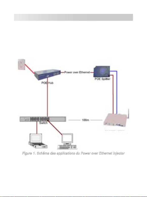
The ASUS ES-101 Power over Ethernet (PoE) Splitter separates data and
power signals sent over a single Ethernet cable from a PoE Hub or Injector,
and feeds data and power over two discrete Ethernet lines to network
devices that are not IEEE802.3af compatible. The following figure shows
the how PoE Splitter works.
Figure 1. Power over Ethernet Splitter Application Architechture
2
Features
• IEEE802.3af compatible
• Power & data delivery via Ethernet cable to equipment that are not
IEEE802.3af compatible
• For Wireless AP, Bluetooth AP, IP Camera, IP Telephones, and other
remote power feeding application devices
• 5v, 7.5v, 9v, 12v adjustable power output
• Short circuit protection
• Output voltage selection to meet the power demand of different types
of PDs.
• Plug-and-Play
• Light weight and compact size
Hardware Description
The Power over Ethernet Splitter has three connection ports, one LED
indicator, and Dipswitch for voltage adjusting. We will description each in
following.
•
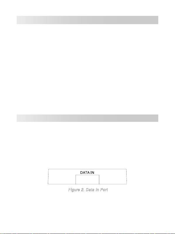
Data In port:
An RJ-45 Ethernet port for data transmit to the PoE
Splitter. It is for connecting with PoE injector or PoE Switch.
Figure 2. Data In Port
3
•
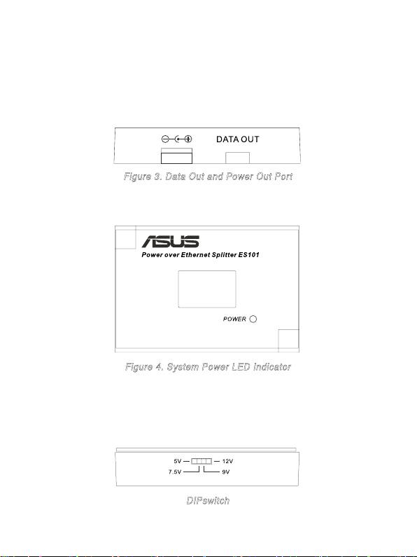
Data Out port:
An RJ-45 Ethernet port with fixed RJ-45 cable for
connection with PD devices.
•
Power Out port:
The power jack that transmits power to devices which
work under 5V, 7.5V, 9V or 12V. It supports two types of power cable: 5.5
x2.0mm and 5.5x2.5mm, both included in the package of PoE Splitter.
Figure 3. Data Out and Power Out Port
•
LED indicator:
The Power LED.
Figure 4. System Power LED Indicator
•
DIPswitch:
Output voltage switch. It provides four levels of power
output – 5V, 7.5V, 9V and 12V. The default voltage is set to 5V. Before
you adjust the Dipswitch, make sure the PoE Splitter is powered off.
DIPswitch
4

Installation
Follow the steps below to install the PoE Splitter:
1. Before installing the PoE Splitter, make sure that all devices are cut from
power supply.
2.Connect the
Data
In port on the PoE Splitter with the
Data out
port on
your PoE Switch or Hub. If your Switch or Hub does not support PoE
function, you need to install a PoE injector between your Switch/HUB and
PoE Splitter.
3. Use an Ethernet cable to connect the
Data out
port on the PoE Splitter to
the RJ-45 port on your PD (Such as Router, Access Point...etc.)
4. Choose the power cable that goes with your PD power port.
5. Use the power cable to connect the PoE Splitter Power Out jack with the
PDʼs power jack.
6. Adjust the Voltage according to the specification of your PD. The PoE
Splitter supports four type of voltage – 5V, 7.5V, 9V and 12V.
The default
value is set to 5V
. Before you adjust the voltage, make sure the PoE
Splitter is powered off.
5

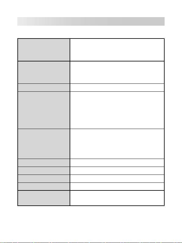
Technical Specification
The following table shows the technical specification of the PoE Splitter.
IEEE802.3 10BASE-T
Standard
IEEE802.3u 100BASE-T
IEEE802.3af Power over Ethernet
2 x power cable (straight/ right angle plug)
Power jack diameter
Plug dimension:
5.5mm x 2.0mm, 5.5mm x 2.5mm
Adjust Switch
4 output voltage selection.
Data and Power In: 1 x RJ-45. Data pin 1,2,3,6
Power pin: 4,5 (V+), 7,8 (V-), 1,2 (V+), 3,6 (V-)
Connector
Data out: 1 x RJ-45, Data pin 1,2,3,6
Power out jack: 5V, 7.5V, 9V, 12V (Adjustable)
Maximum feeding current: 2.0A@5V
10BASE-T: 2 pair UTP/STP Cat.3,4,5 cable
EIA/TIA-568 100-ohm (100m)
Network Cable
100BASE-TX: 2 pair UTP/STP Cat.5 cable
EIA/TIA-568 100-ohm (100m)
LED
System: power (green)
Power Input
DC 48V
Operating environment
0˚C~40˚C, 90% Humidity (non-condensing)
Dimension
80mm x 55mm x 26mm (L x W x H)
FCC Class B, CE, CE/EN60950, VCCI, MIC,
EMI & Safety
UL, CCC
6

Power over Ethernet Splitter
avec sortie ajustable
Guide de l’utilisateur
ES-101
7
Vue générale
Le Power over Ethernet (PoE) Splitter ES-101 d'ASUS sépare donnée et
alimentation grâce à un câble Ethernet depuis un PoE Hub ou Injector, et
alimente en donnée et en courant électrique, via deux lignes Ethernet, les
appareils non compatibles avec la norme IEEE802.3af. La figure suivante
est un schéma des applications du Power over Ethernet Injector.
Routeur sans fil
Figure 1. Schéma des applications du Power over Ethernet Injector
8

Fonctions
• Compatible avec la norme IEEE802.3af
• Alimente en données et en courant électrique les appareils non
compatibles avec la norme IEEE802.3af
• Pour les points d'accès sans fil et Bluetooth, les caméras et téléphones
réseau, et autres appareils pouvant être alimentés à distance
• Sortie dʼalimentation ajustable: 5v, 7.5v, 9v, 12v
• Protection contre les courts-circuits
• Régulation de la sortie dʼalimentation grâce à un interrupteur pour
satisfaier les besoind électriques des different types d'appareils.
• Plug-and-Play
• Léger et compacte
Description matérielle
Le Power over Ethernet Splitter possède trois ports de connexion, une
LED dʼalimentation, ainsi quʼun Dipswitch (interrupteur à position multiple)
permettant dʼajuster la tension. Vous trouverez ci-dessous une description
de chaque port.
•
port Data In :
Port réservé à un câble Ethernet RJ-45 pour la
transmission de données vers le PoE Splitter. Sert à être connecté au
PoE Injector.
Figure 2. Port Data In
9
•
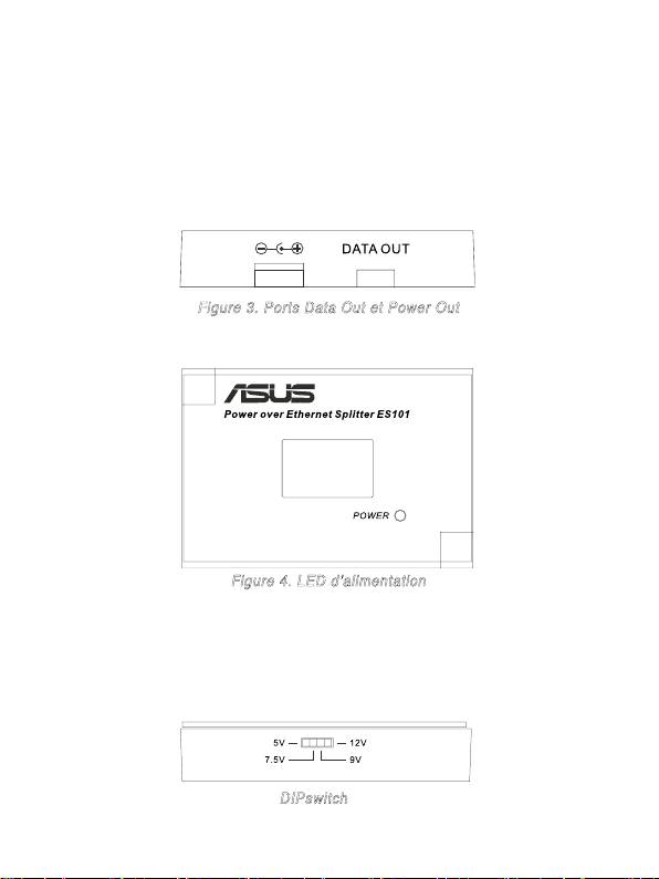
Port Data Out :
Port réservé à un câble Ethernet RJ-45 pour se
connecter à un périphérique PD (Powered Devices).
•
Power Out port:
Supporte deux types de cables dʼalimentation –
5.5 x2.0mm et 5.5x2.5mm. Ces deux types de jack sont contenus
dans la boîte accompagnant le produit. Le port Power Out sert à
transmettre lʼalimentation au périphérique en 5V, 7.5V, 9V ou 12V.
Figure 3. Ports Data Out et Power Out
•
LED d'activité:
LED d'alimentation.
Figure 4. LED dʼalimentation
•
DIPswitch:
Permet dʼajuster le voltage des PD (Powered Devices).
Quatre valeurs de tension sont disponibles – 5V, 7.5V, 9V et 12V. La
valeur par défaut est 5V. Lorsque vous ajustez le Dipswitch, veillez à
éteindre le Power over Ethernet Splitter.
DIPswitch
10

Installation
Pour installer le Power over Ethernet Injector, veuillez suivre les étapes
suivantes.
1. Avant d'installer le PoE Splitter, assurez-vous que tous les appareils sont
hors tension.
2.Utilisez un câble RJ-45 pour connecter le port Data in du Power over
Ethernet Splitter au port Data out du Switch/HUB PoE. Si le Switch/HUB
ne supporte pas la fonction PoE, vous aurez besoin dʼinstaller un PoE
injector entre le Switch/HUB et le PoE Splitter.
3. Utilisez un câble RJ-45 pour connecter le port Data out du Power over
Ethernet Splitter au PD (Powered Devices : tel quʼun Routeur, Access
Point...etc.)
4. Utilisez un câble dʼalimentation (Diamètre:2.0mm ou 2.5mm) et
connectez-le au port Power out du Power over Ethernet Splitter.
5. Connectez le câble dʼalimentation du Power over Ethernet Splitter au
connecteur dʼalimentation du PD.
6. Ajustez la tension du PD en utilisant le Dipswitch du Power over Ethernet
Splitter. Quatre valeurs de tension sont disponibles – 5V, 7.5V, 9V et 12V.
La valeur par défaut est 5V. Lorsque vous ajustez le Dipswitch, veillez à
éteindre le Power over Ethernet Splitter.
11
Technical Specification
Le tableau suivant fournit les spécifications techniques du PoE Splitter.
IEEE802.3 10BASE-T
Standards
IEEE802.3u 100BASE-T
IEEE802.3af Power over Ethernet
2 câbles dʼalimentation avec une prise droite
Diamètre des jacks
et une prise à angle droit
d'alimentation
dimensions: 5.5 x 2.0mm, 5.5 x 2.5mm
Interrupteur de tension
4 valeurs de tension disponibles.
Data et power in: 1 x RJ-45.Data pin 1,2,3,6
Power pin: 4,5(V+), 7,8(V-) and 1,2(V+), 3,6(V-)
Connecteur
Data out: 1 x RJ-45, Data pin 1,2,3,6
Jack Power out: 5V, 7.5V, 9V, 12V (Ajustable)/
courant dʼalimentation maximum: 2.0A@5V
10BASE-T: 2 pair UTP/STP Cat.3,4,5
EIA/TIA-568 100-ohm (100m)
Câble réseau
100BASE-TX: 2 pair UTP/STP Cat.5
EIA/TIA-568 100-ohm (100m)
LED
Système: alimentation (vert)
Power Input
DC 48V
Entrée dʼalimentation
0˚C~40˚C, 90% dʼhumidité (sans condensation)
Dimensions
80mm x 55mm x 26mm (L x W x H)
FCC Classe B, CE, CE/EN60950, VCCI, MIC,
EMI & Sécurité
UL, CCC
12

Power over Ethernet
Splitter mit einstellbarer
Ausgangsspannung
Benutzeranleitung
ES-101
13
Übersicht
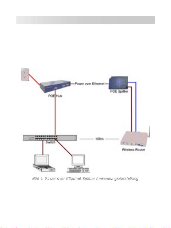
Der ASUS ES-101 Power over Ethernet (PoE)-Splitter trennt die vom
Hub oder PoE-Injektor gesendeten Daten von der Ausgangsspannung
und und schickt die Daten über zwei einzelne Ethernet-Kabel zu den
Netzwerkgeräten, die nicht IEEE802.3af kompatibel sind. Das folgende Bild
zeigt Ihnen die Arbeitsweise des PoE-Splitters.
Bild 1. Power over Ethernet Splitter Anwendungsdarstellung
14

Funktionen
• IEEE802.3af kompatibel
• Spannung & Daten werden mittels Ethernet-Kabel zu den Geräten
geschickt, die nicht IEEE802.3af kompatibel sind
• Für Wireless AP, Bluetooth AP, IP-Kamera, IP-Telefone, Spannungs-
fernversorgungsanwendungen
• 5V, 7.5V, 9V, 12V regelbare Ausgangsspannung
• Kurzschlussschutz
• Ausgangsspannungsregelung, um verschiedenen Typen von PDs zu
versorgen.
• Plug-and-Play
• Leichte und kompakte Bauweise
Hardware-Beschreibung
Der Power-over-Ethernet-Splitter hat drei Anschlüsse, eine LED-Anzeige
und DIP-Schalter zur Spannungseinstellung. Wir beschreiben alles im
folgenden Abschnitt.
•
Dateneingangsanschluss:
Ein RJ-45-Ethernet-Anschluss zur
Datenübertragung zum zum PoE-Splitter. Nicht zur Verbindung mit
einem PoE-Injektor oder PoE-Switch.
Bild 2. Dateneingangsanschluss
15
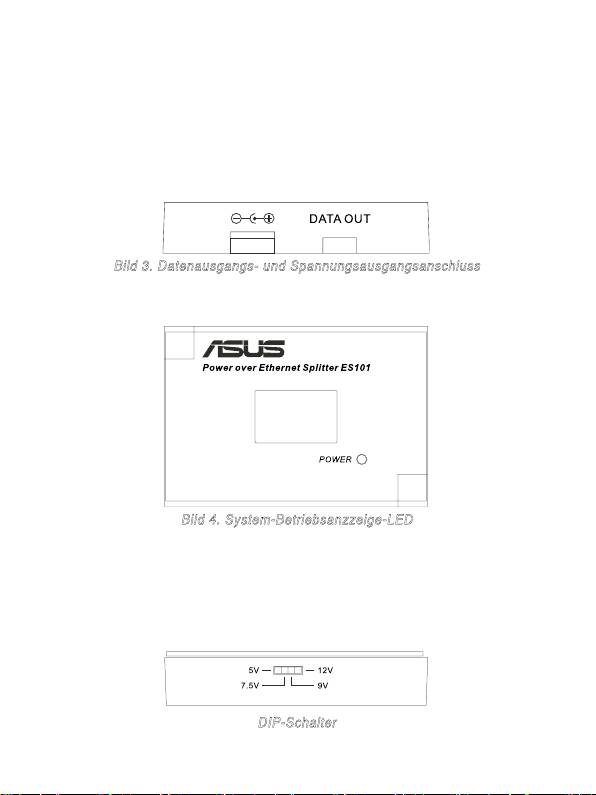
•
Datenausgangsanschluss:
Ein RJ-45-Ethernet-Anschluss mit fest
angeschlossenem RJ-45-Kabel zur Verbindung mit PD-Geräten.
•
Spannungsausgangsanschluss:
Der Spannungsausgang liefert die
Spannung zu den Geräten welche mit 5V, 7,5V, 9V oder 12V arbeiten.
Er unterstützt zwei Arten von Kabeln: 5,5 x2.0mm und 5,5x2.5mm, beide
sind der Verpackung des PoE-Splitters beigelegt.
Bild 3. Datenausgangs- und Spannungsausgangsanschluss
•
LED-Anzeige:
Die Betriebsanzeige-LED.
Bild 4. System-Betriebsanzzeige-LED
•
DIP-Schalter:
Ausgangsspannungsumschalter. Er stellt vier
Ausgangsspannungen zur Verfügung – 5V, 7,5V, 9V und 12V. Die
Standardspannung ist 5V. Vor der Einsellung des DIP-Schalters,
vergewissern Sie sich bitte, dass der PoE-Splitter ausgeschaltet ist.
DIP-Schalter
16

Installation
Bitte folgen Sie den Schritten der Anleitung, um den Power-over-Ethernet-
Splitter zu installieren:
1. Vor der Installation des PoE-Splitters vergewissern Sie sich bitte, dass
alle Geräte von der Stromversorgung getrennt wurden.
2.Verbinden Sie den
Dateneingangsanschluss
des PoE-Splitters mit den
Datenausggangsanschluss
des PoE-Switch oder Hub. Wenn Ihr Switch
oder Hub die PoE-Funktion nicht unterstützen, müssen Sie den PoE-
Injektor zwischen dem Switch/Hub und dem PoE-Splitter installieren.
3. Verwenden Sie ein Ethernet-Kabel, um den
Datenausgangsanschluss
des PoE-Splitters mit dem RJ-45-Anschluss des PD (z.B. Router, Access
Point...etc.) zu verbinden
4. Wählen Sie ein Stromversorgungskabel welches zum PD-Anschluss
passt.
5. Benutzen Sie das Stromversorgungskabel, um den PoE-Splitter-Spann-
ungsausgang mit des Spannungsbuchse des PD zu verbinden.
6. Stellen Sie die Spannung entsprechend den Daten des PD. Der PoE-
Splitter unterstützt vier Spannungen – 5V, 7,5V, 9V und 12V.
Der
Standardwert ist 5V
. Vor der Einstellung der Spannung, vergewissern
Sie sich bitte, dass der PoE-Splitter ausgeschaltet ist.
17

Technische Daten
Die folgende Tabelle zeigt Ihnen die technischen Daten des Powwer-over-
Ethernet-Splitters.
IEEE802.3 10BASE-T
Standard
IEEE802.3u 100BASE-T
IEEE802.3af Power over Ethernet
Spannungsbuchsen-
2 x Kabel (gerade/rechtwinkliger Stecker)
durchmesser
Steckerabmessungen:
5,5mm x 2,0mm, 5,5mm x 2,5mm
Einstellschalter
4 Ausgangsspannungen
Daten & Spannungseingang: 1 x RJ-45. Daten-
Pin 1,2,3,6
Spannungs-Pin: 4,5(V+), 7,8(V-), 1,2(V+), 3,6(V-)
Verbindungen
Datenausgang: 1 x RJ-45, Daten-Pin 1,2,3,6
Spannungsausgang: 5V, 7,5V, 9V, 12V (regelbar)
Maximaler Strom: 2.0A@5V
10BASE-T: 2 Pair UTP/STP Cat.3,4,5 Kabel
EIA/TIA-568 100-Ohm (100m)
Netzwerkkabel
100BASE-TX: 2 Pair UTP/STP Cat.5 Kabel
EIA/TIA-568 100-Ohm (100m)
LED
System: Betriebsanzeige (grün)
Spannungseingang
Gleichspannung 48V
Betriebsumgebung
0˚C-40˚C, 90% nicht kondensierende Luftfeuchte
Abmessungen
80mm x 55mm x 26mm (L x B x H)
FCC Klasse B, CE, CE/EN60950, VCCI, MIC,
EMI & Sicherheit
UL, CCC
18

Separatore PoE (Power over Ethernet)
con rendimento regolabile
Manuale dell’Utente
ES-101
19
