Asus T3-P5945GCX: instruction
Class: Computer equipment, hardware, accessories
Type:
Manual for Asus T3-P5945GCX
Table of contents
- Front/Rear panel features
- Internal components Removing the cover
- Lifting the power supply unit Installing a CPU Installing an Intel CPU in the LGA775 package
- Installing an AMD CPU Installing the CPU fan and heatsink assembly Installing an Intel CPU heatsink and fan
- Installing an AMD CPU heatsink and fan Installing a DIMM
- Installing an expansion card Installing a hard disk drive
- Installing an optical drive Reinstalling the cover
English
T-Series
ASUS PC (Desktop Barebone)
Installation manual
Download the latest manual from the ASUS website: www.asus.com
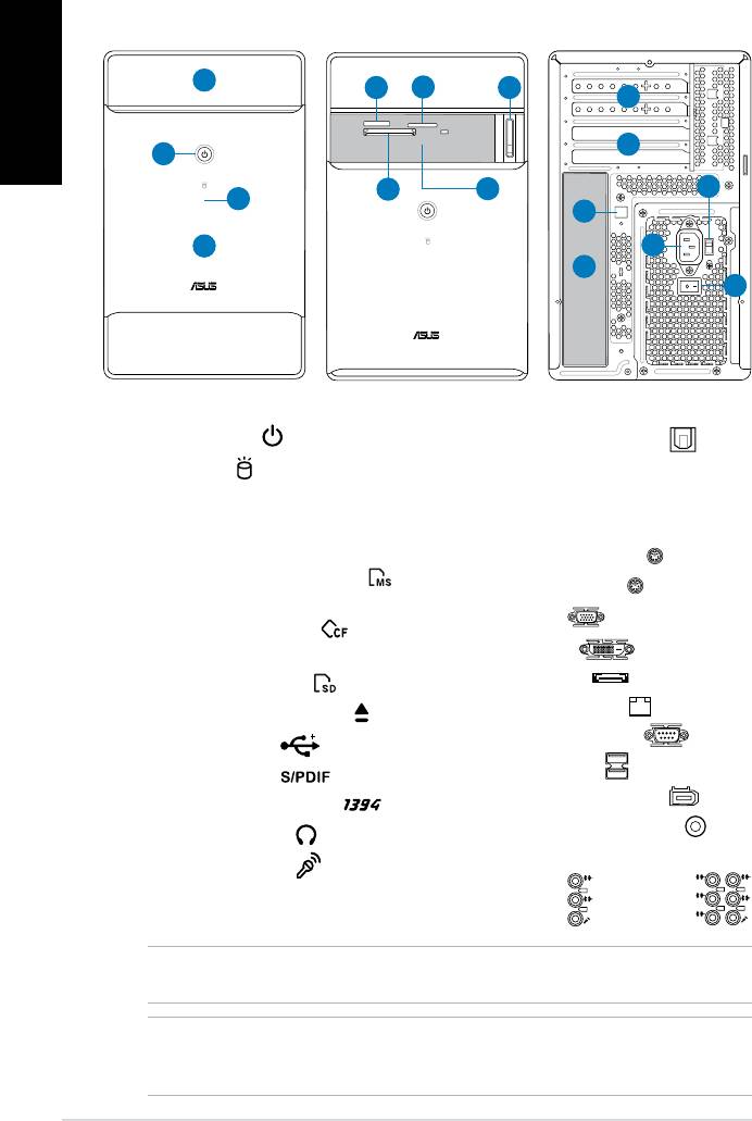
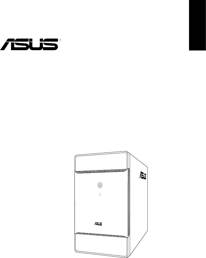
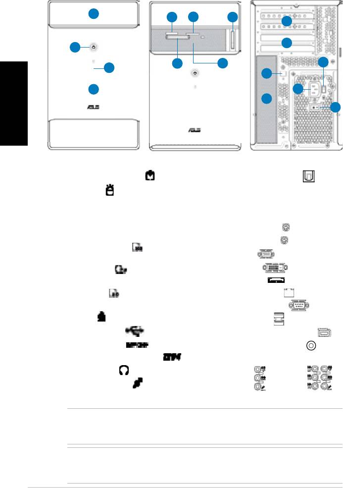
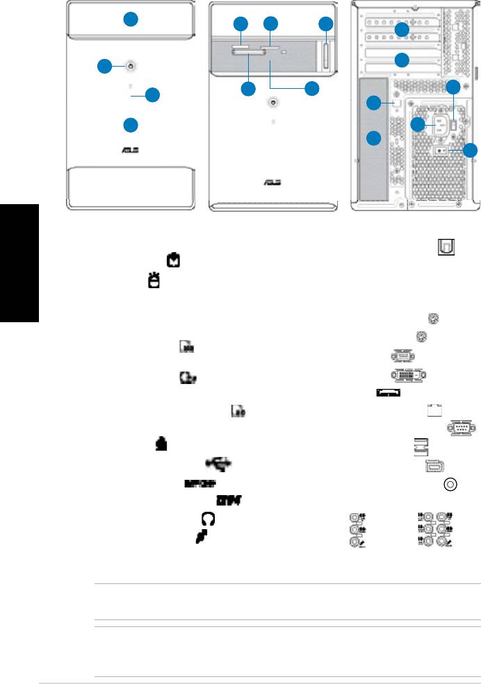
Front/Rear panel features
English
1. Optical drive bay cover
11. Expansion slots
2. Power button (
)
12.* Optical S/PDIF Out port (
)
3. HDD LED (
)
(lights up when
13. Power connector
the hard disk drive operates)
14.** Voltage selector switch
4. Front panel cover
15. Power switch
5. Memory Stick/
16.* • PS/2 keyboard port (
)
Memory Stick Pro card slot ( )
• PS/2 mouse port (
)
®
6. CompactFlash
/
• VGA port (
)
™
Microdrive
card slot ( )
• DVI-D port (
)
7. Secure Digital/
• E-SATA port (
)
MultiMediaCard slot ( )
• LAN (RJ-45) port (
)
8. Optical drive eject button ( )
• Serial (COM1) port (
)
9.* • USB 2.0 ports (
)
• USB 2.0 ports (
)
• S/PDIF In port (
)
• 6-pin IEEE 1394a port (
)
• 4-pin IEEE 1394a port (
)
• Coaxial S/PDIF Out port (
)
• Headphone port (
)
•Audioportscongurations:
• Microphone port (
)
10. Expansion slot metal brackets
• 6-channel
2 Installation manual
L
IN
IN
E
FR
O
N
T
M
IC
IN
• 8-channel
C
BA
S
T
S
R
L
IN
IN
E
R
S
E
P
A
K
R
FR
O
N
T
S
S
P
ID
K
E
M
IC
IN
Front (Close)
Front (Slide open)
Rear
1
5
7
8
10
11
2
6
9
14
3
12
4
13
16
15
NOTE: *The front/rear panel ports and their locations may vary, depending on the
model of your system. For detailed descriptions, refer to the system User Guide.
NOTE: **The system’s power supply unit has a 115V / 230V voltage selector switch
located beside the power connector. Use this switch to select the appropriate system
input voltage according to the voltage supply in your area.
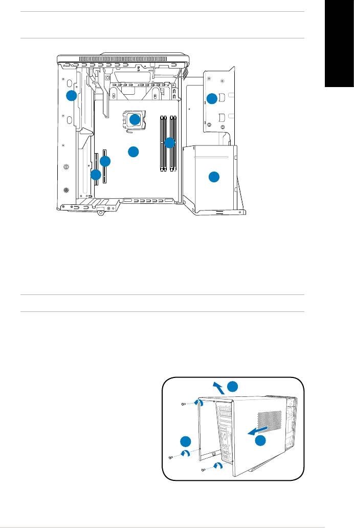
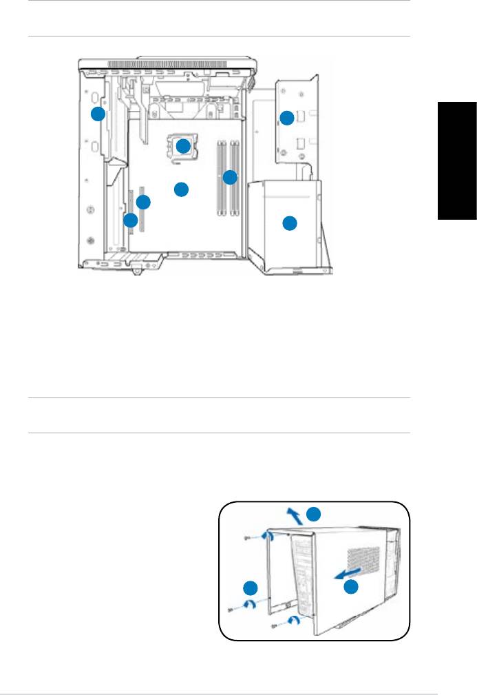
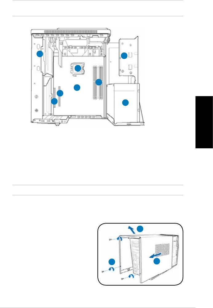
Internal components
NOTE: The illustration below shows the internal view of the system when you remove
the cover and lift the power supply unit.
English
1
2
5
4
6
7
8
3
1. 5.25-inch optical drive cage
5. CPU socket
2. 3.5-inch hard disk drive cage
6.* ASUS motherboard
3. Power supply unit
7. PCI Express x16 slot
4. DIMM sockets
8. PCI slot
NOTE: *Refer to the system User Guide for motherboard details.
Removing the cover
1. Remove the three cover screws on
3
the rear panel. Keep the screws for
later use.
2. Pull the cover toward the rear panel.
3. Lift the cover, then set it aside.
1
2
3Installation manual
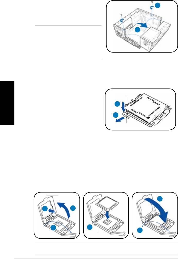
Lifting the power supply unit
1. Locate and remove the two screws.
English
1
2. Lift the PSU in the direction of the
arrow to a 90º angle.
2
CAUTION: When removing the PSU,
makesuretoholdorsupportitrmly.
The unit might accidentally drop and
damage the other system components.
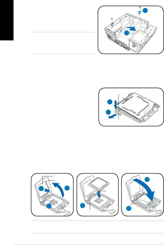
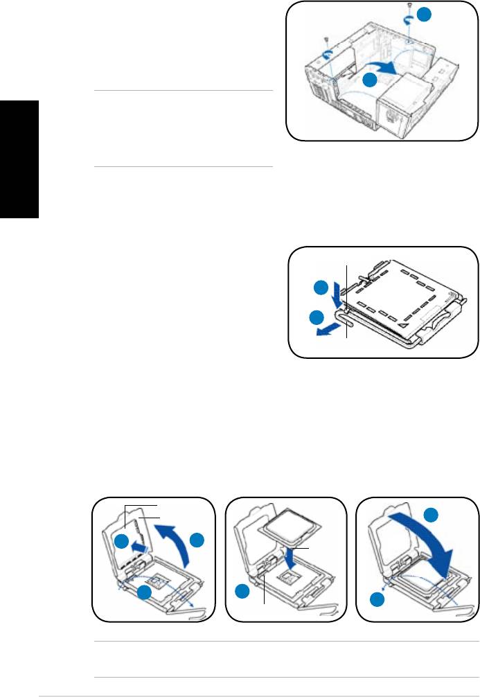
Installing a CPU
®
Installing an Intel
CPU in the LGA775 package
1. Locate the CPU socket on the
Retention tab
motherboard.
2. Press the load lever with your
2A
thumb (2A), then move it to the left
(2B) until it is released from the
2B
retention tab.
Load lever
3. Lift the load lever in the direction of
the arrow to a 135º angle.
4. Lifttheloadplatewithyourthumbandforengertoa100ºangle(4A),then
push the PnP cap from the load plate window to remove (4B).
5. Position the CPU over the socket, making sure that the gold triangle is on the
bottom-left corner of the socket. Fit the socket alignment key into the CPU
notch.
6. Close the load plate (6A), then push the load lever (6B) until it snaps into the
retention tab.
PnP cap
Load plate
6A
Gold
4B
4A
triangle
mark
3
5
6B
Alignment key
CAUTION: Incorrect installation of the CPU into the socket may bend the pins and
severely damage the CPU.
4 Installation manual
Installing an AMD CPU
1. Locate the CPU socket, then lift the socket lever to a 90º angle.
2. Install the CPU to the socket, making sure that the CPU corner with the gold
triangle matches the socket corner with a small triangle.
3. Push down the socket lever to secure the CPU.
English
1
2
3
CAUTION: Incorrect installation of the CPU into the socket may bend the pins and
severely damage the CPU.
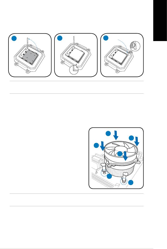
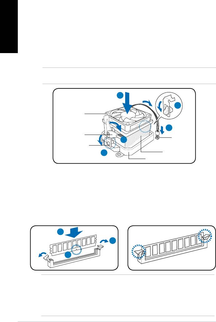
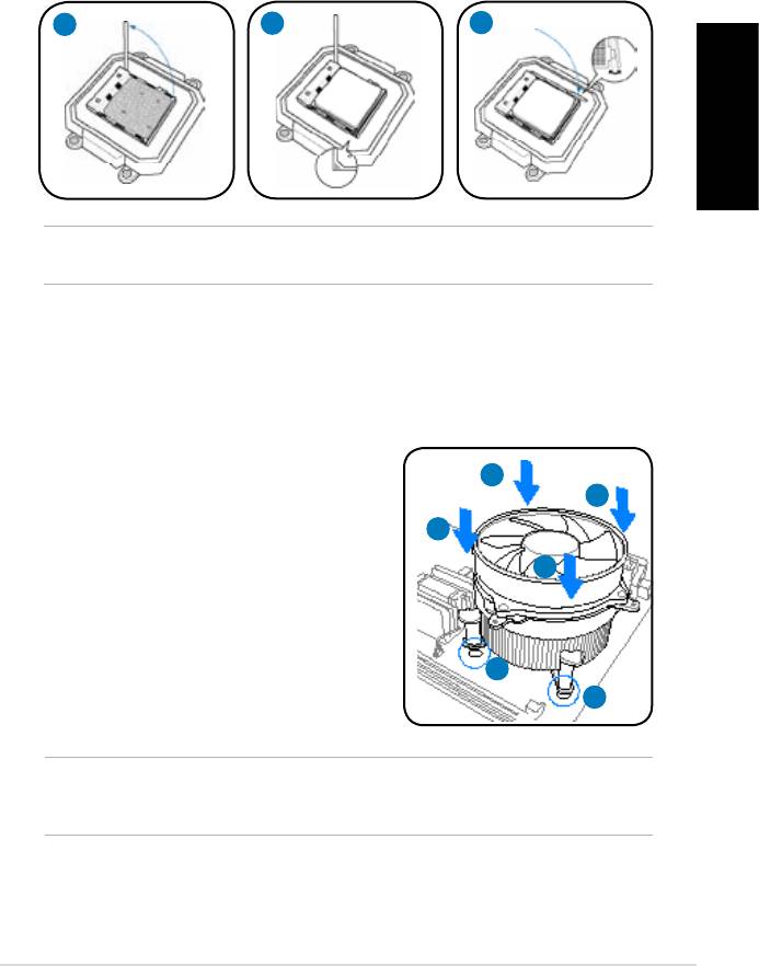
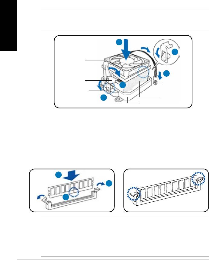
Installing the CPU fan and heatsink assembly
®
Installing an Intel
CPU heatsink and fan
1. Place the heatsink on top of the installed
A
CPU, making sure that the four fasteners
B
match the holes on the motherboard.
B
2. Push down two fasteners at a time in a
diagonal sequence to secure the heatsink
A
and fan assembly in place.
3. When the fan and heatsink assembly is in
place, connect the CPU fan cable to the
connector on the motherboard.
1
1
CAUTION. Do not forget to connect the CPU fan connector! Hardware monitoring error
can occur if you fail to plug this connector.
5Installation manual
Installing an AMD CPU heatsink and fan
English
1. Place the heatsink on top of the installed CPU.
2. Attach one end of the retention bracket to the retention module base.
3. Attach the other end of the retention bracket (near the retention bracket lock)
to the retention module base until it clicks in place.
4. Push down the retention bracket lock on the retention mechanism to secure
the fan and heatsink to the module retention module base.
5. Connect the CPU fan cable to the connector on the motherboard.
CAUTION. Do not forget to connect the CPU fan connector! Hardware monitoring error
can occur if you fail to plug this connector.
1
2
CPU fan
5
Retention
CPU fan
bracket lock
4
connector
Retention bracket
3
CPU heatsink
Retention module base
Installing a DIMM
1. Locate the DIMM sockets in the motherboard.
2. Unlock a DIMM socket by pressing the retaining clips outward.
3. Align a DIMM on the socket such that the notch on the DIMM matches the
break on the socket.
4. Push the DIMM to the socket until the retaining clips snap inward.
4
2
3
CAUTION:
• Unplug the power supply before adding or removing DIMMs. Failure to do so may
cause damage to the motherboard and/or components.
• ADDRDIMMiskeyedwithanotchsothatittsinonlyonedirection.Donotforce
a DIMM into a socket to avoid damaging the DIMM.
6 Installation manual
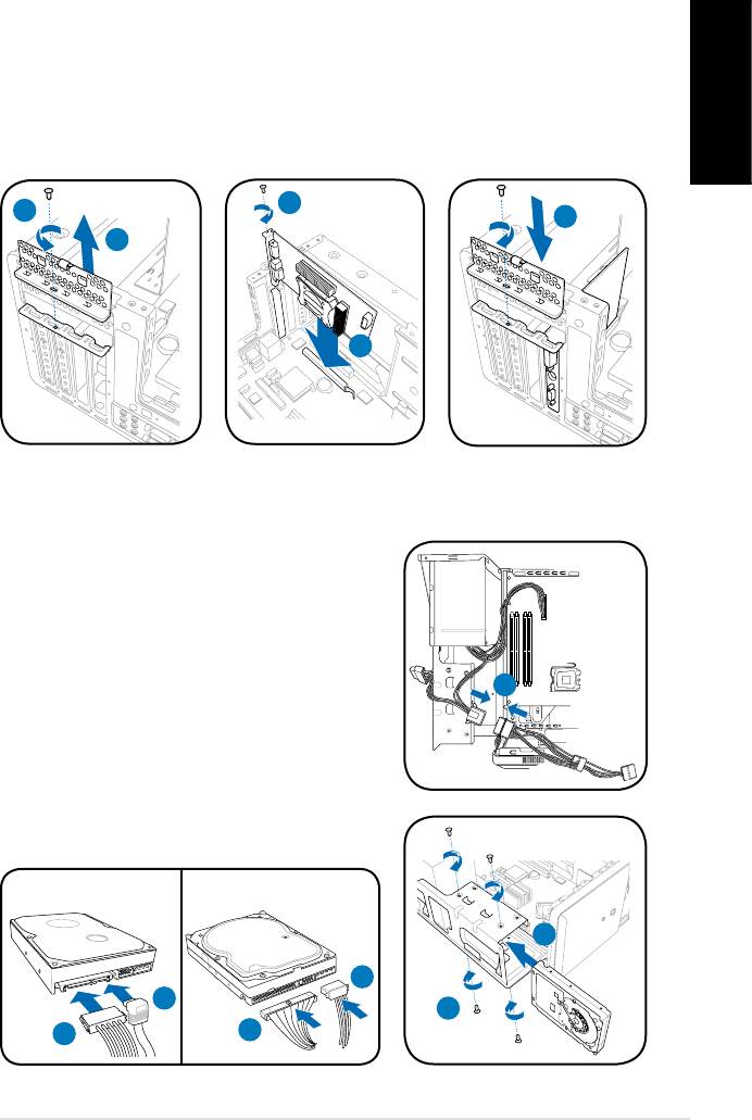
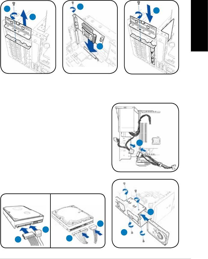
Installing an expansion card
1. Locate and remove one metal bracket lock screw.
2. Remove the metal bracket lock.
3. Alignthecardconnectorwiththeslot,thenpressrmly.
4. Secure the card with one screw.
English
5. Replace the metal braket lock, then secure it with one screw.
4
1
5
2
3
Installing a hard disk drive
1. Connect the SATA/IDE power cable to the
plug of the power supply unit.
2. Connect the SATA/IDE (2A) and power (2B)
plugs to the connectors at the back of the
SATA/IDE hard disk drives.
3. Locate the HDD tray.
1
4. Insert a hard disk drive (with the HDD PCB
facing the top of the chassis) to the tray,
then secure it with four screws.
5. Connect the SATA/IDE signal cable to the
SATA/IDE connector on the motherboard, and
tighten all the cables with the plastic coils.
SATA
IDE
4
2B
2A
4
2A
2B
7Installation manual
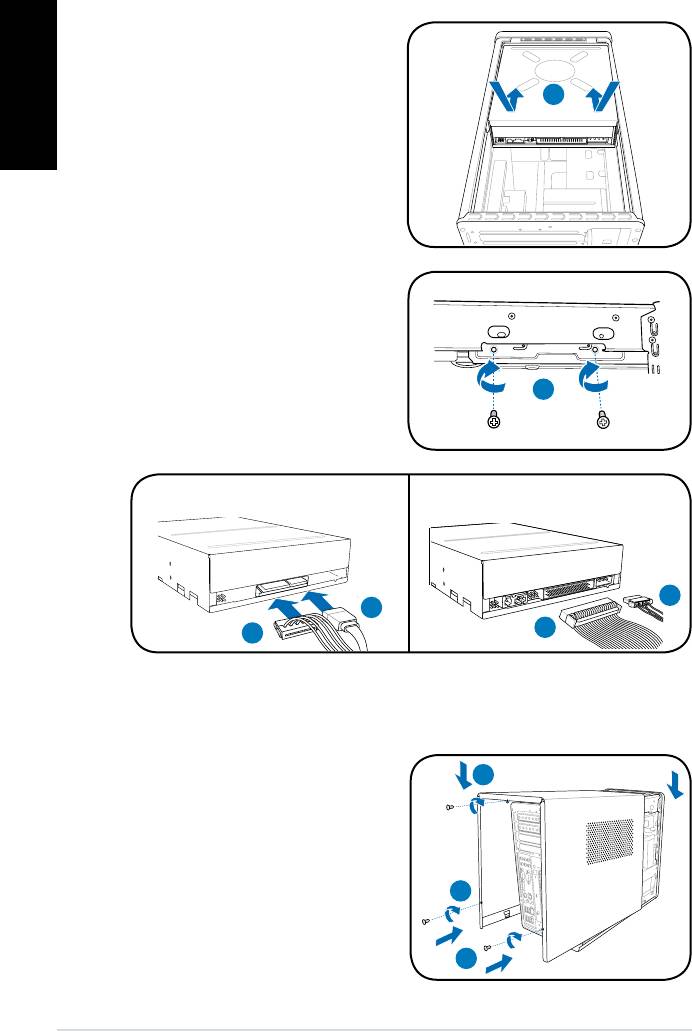
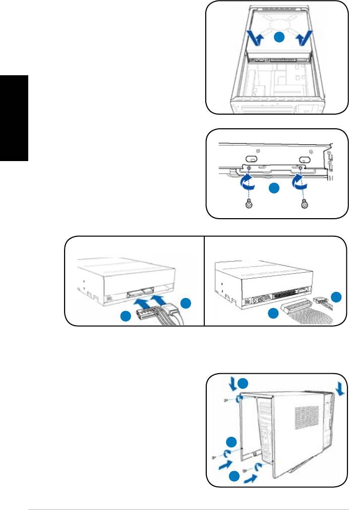
Installing an optical drive
1. Place the chassis upright.
English
2. Insert the SATA/IDE optical drive
to the upper 5.25 in drive bay, then
2
carefully push the drive until its
screw holes align with the holes on
the bay.
3. Secure the optical drive with four
screws on both sides of the bay.
4. Connect the SATA/IDE (4A) and
power plugs (4B) to the connectors
at the back of the SATA/IDE drive.
3
SATA IDE
4B
4A
4A
4B
Reinstalling the cover
1. Fit the cover tabs with the chassis
1B
rail and the front panel tabs (1A),
then lower the rear edge of the
cover as shown (1B).
2. Secure the cover with three screws.
2
1A
8 Installation manual
T-Série
ASUS PC (Système barebone)
Français
Manuel d’installation
Téléchargez les derniers manuels depuis le site web d’ASUS: www.asus.com
Caractéristiques de la façade/de l’arrière
Façade (Fermé)
Façade (Ouvert)
Arrière
1
5
7
8
10
11
2
6
9
14
3
12
Français
4
13
16
15
1. Capot de la baie du lecteur optique
11. Slots d’extension
2. Bouton d’alimentation (
)
12.* Port S/PDIF Out optique (
)
13. Connecteur d’alimentation
3. LED HDD (
)
(s’allume lorsque
le disque dur est en cours
14.** Interrupteur de sélection du voltage
d’opération)
15. Interrupteur d’alimentation
4. Façade
16.* • Port clavier PS/2 (
)
5. Slot pour cartes Memory Stick/
• Port souris PS/2 (
)
Memory Stick Pro ( )
• Port VGA (
)
®
6. Slot pour cartes CompactFlash
/
• Port DVI-D (
)
Microdrive™ ( )
• Port E-SATA (
)
7. Slot pour cartes Secure Digital/
MultiMedia ( )
• Port LAN (RJ-45) (
)
8. Bouton d’ejection du lecteur
• Port Série (COM1) (
)
optique ( )
• Ports USB 2.0 (
)
9.* • Ports USB 2.0 (
)
• Port IEEE 1394a 6 broches (
)
• Port S/PDIF In (
)
• Port S/PDIF Out coaxial (
)
• Port IEEE 1394a 4 broches (
)
•Congurationsdesportsaudio:
• Port Casque (
)
• Port Microphone (
)
• 6 canaux
• 8 canaux
10. Expansion slot metal brackets
NOTE: *Les ports/slots du panneau avant/arrière ainsi que leurs emplacements
peuvent varier selon le modèle de votre système. Pour une description détaillée,
reportez-vous au manuel de l’utilisateur de votre système.
NOTE:**L’alimentationdusystèmeestéquipéed’unsélecteurdetension115V/230V
situé près du connecteur d’alimentation. Utilisez cet interrupteur pour choisir la bonne
tension d’entrée en fonction des standards utilisés dans votre région.
2
Manuel d’installation
Internal components
NOTE: L’illustrationci-dessousafcheunevueinternedusystèmelorsquevousretirez
le panneau latéral et soulevez le bloc d’alimentation.
1
2
5
4
6
Français
7
8
3
1. Cage du lecteur optique 5.25”
5. Socket du CPU
2. Cage du lecteur de disque dur
6.* Carte mère ASUS
3.5’’
7. Slot PCI Express x16
3. Alimentation
8. Slot PCI
4. Sockets DIMM
NOTE: *Reportez-vous au manuel de l’utilisateur du système pour plus de détails sur
la carte mère.
Enlever le capot
1. Retirez les trois vis du panneau
3
arrière. Conservez les vis pour un
usage ultérieur.
2. Faites glisser le panneau latéral vers
l’arrière.
3. Soulevez le capot, puis basculez-le.
1
2
Manuel d’installation
3
Soulever le bloc d’alimentation
1. Localisez et retirez les deux vis du
1
bloc d’alimentation.
2. Soulevez l’unité d’alimentation dans
ladirectiondelaèchedansun
angle de 90º.
2
ATTENTION: lorsque vous enlevez
l’alimentation assurez-vous de bien
Français
la tenir car elle pourrait tomber et
endommager les autres composants du
système.
Installer un CPU
®
Installer un processeur Intel
au format LGA775
1. Localisez le socket du CPU sur la
Loquet de rétention
carte mère.
2. Pressez le levier avec votre pouce
2A
(2A) et glissez-le vers la gauche
(2B) jusqu’à ce qu’il soit libéré du
2B
loquet de rétention.
3. Levez le levier dans la direction de
Levier
laècheàunanglede135º.
4. Levez la plaque avec votre pouce à un angle de 100°(4A), puis poussez le
couvercle PnP de la plaque pour l’enlever (4B).
5. Placez le CPU au dessus du socket, en vous assurant que le triangle doré
soit dans le coin inférieur gauche du socket. La clef d’alignement du socket
doit correspondre avec l’encoche du CPU.
6. Refermez la plaque (6A), puis poussez le levier (6B) jusqu’à ce qu’il soit
accroché par le loquet de rétention.
Plaque de
protection
6A
Plaque
4B
4A
Marque
triangulaire
dorée
3
5
6B
Clef d’alignement
ATTENTION: Une mauvaise installation du CPU sur le socket peut plier les broches et
sérieusement endommager le CPU!
4
Manuel d’installation
Installer le AMD CPU
1. Repérez le socket du CPU, puis soulever le levier du socket de 90°.
2. Placez le CPU sur le socket, en vous assurant que le triangle doré sur le
CPU est installé sur le triangle du socket.
3. AbaissezlelevierdusocketandesécuriserleCPU.
1
2
3
Français
ATTENTION: Une mauvaise installation du CPU sur le socket peut plier les broches et
sérieusement endommager le CPU!
Installer l’ensemble dissipateur-ventilateur
®
Installer un ensemble dissipateur-ventilateur pour processeur Intel
1. Placez le dissipateur sur le processeur, en
vous assurant que les quatres systèmes de
A
serrage correspondent aux trous de la carte
B
mère.
B
2. Pressez sur deux systèmes de serrage à
A
lafoisenséquencediagonalepourxer
l’ensemble dissipateur-ventilateur.
3. Lorsque l’ensemble dissipateur-ventilateur
est en place, connectez le câble du
1
ventilateur CPU au connecteur de la carte
mère étiqueté CPU_FAN.
1
ATTENTION: N’oubliez pas de connecter le câble du ventilateur au connecteur de la
carte mère! Des erreurs lors de la surveillance du matériel peuvent survenir si vous ne
branchez pas ce connecteur.
Manuel d’installation
5
Installer un ensemble dissipateur-ventilateur pour processeur AMD
1. Placez l’ensemble ventilateur-dissipateur sur le CPU.
2. Fixezuneextrémitédelapattedexationaumodulederétention.
3. Fixezl’autreextrémitédelapattedexation(prèsduclipdexation)au
module de rétention jusqu’à ce qu’un clic se fasse entendre.
4. Abaissezlesloquetsdexationdumodulederétentionandesécuriser
l’ensemble dissipateur-ventilateur à la base du module.
5. Connectez le câble du ventilateur CPU au connecteur de la carte mère.
Français
ATTENTION: N’oubliez pas de connecter le câble du ventilateur au connecteur de la
carte mère! Des erreurs lors de la surveillance du matériel peuvent survenir si vous ne
branchez pas ce connecteur.
1
2
Ventilateur CPU
5
Clip de la patte
Connecteur du
dexation
4
ventilateur CPU
Pattedexation
3
Dissipateur CPU
Base du module de rétention
Installer un module DIMM
1. Localisez les sockets DIMM de la carte mère.
2. Déverrouillez un socket DIMM en pressant sur les clips de rétention vers l’extérieur.
3. Alignez un module DIMM sur le socket de sorte que l’encoche sur la DIMM
corresponde à l’ergot du socket.
4. Enfoncez le module DIMM dans le socket jusqu’à ce que les clips de
rétention se referment.
4
2
3
ATTENTION:
• Débranchez la source d’alimentation avant d’ajouter ou de retirer des modules
DIMMs. Ne pas le faire peut endommager la carte mère et/ou les composants.
• Un module DDR DIMM est verrouillé par une encoche, de sorte qu’il ne peut
entrer dans le socket que dans un seul sens. NE FORCEZ pas sur un module
pour le faire entrer dans son socket pour ne pas l’endommager.
6
Manuel d’installation
Installer une carte d’extension
1. Repérez et retirez une des vis de blocage de l’attache métallique.
2. Retirez la sécurité de l’attache métallique.
3. Alignez le connecteur de la carte sur le slot, puis insérez-le fermement.
4. Fixez la carte à l’aide d’une vis.
5. Repositionnezlasécurité,puisxez-laàl’aided’unevis.
4
1
5
2
Français
3
Installer un disque dur
1. Connectez le câble d’alimentation SATA/
IDE à la prise du bloc d’alimentation.
2. Connectez les prises SATA/IDE (2A) et
d’alimentation (2B) au connecteurs localisés
à l’arrière des disques durs SATA/IDE.
3. Repérez la baie pour disque dur.
1
4. Insérez un disque dur (les circuits imprimés
orientés vers le haut du châssis) dans la
baie,puisxez-leàl’aidedequatrevis.
5. Reliez le câble SATA/IDE au connecteur
SATA/IDE de la carte mère. Regroupez les
câbles à l’aide des anneaux en plastique.
SATA
IDE
4
2B
2A
4
2A
2B
Manuel d’installation
7
Installer un lecteur optique
1. Mettez le châssis en position
verticale.
2. Insérez le SATA/IDE lecteur optique
2
dans la baie 5.25” supérieure, puis
faites le coulisser avec précaution,
jusqu’à ce que ses pas de vis
s’alignent avec ceux de la baie.
Français
3. Fixez-le de part et d’autre de la baie
à l’aide de quatre vis.
4. Connectez les câbles SATA/IDE
(4A), et d’alimentation (4B) aux
connecteurs situés à l’arrière du
3
lecteur.
SATA IDE
4B
4A
4A
4B
Réinstaller le panneau
1. Alignez les onglets du capot avec
1B
le rail du châssis et les onglets de
la façade (1A), puis baissez le bord
arrière comme indiqué (1B).
2. Fixez le capot avec trois vis.
2
1A
8
Manuel d’installation
T-Serie
ASUS PC (Desktop Barebone)
Installationshandbuch
Deutsch
Die neueste Version des Handbuchs nden Sie auf der ASUS-Website: www.asus.com
Frontseite/Rückseite
Vorderseite (geschlossen)
Vorderseite (aufschieben)
Rückseite
1
5
7
8
10
11
2
6
9
14
3
12
4
13
16
15
Deutsch
1. Schubladenabdeckung des
11. Erweiterungs-steckplätze
optischen Laufwerkes
12.* Optischer S/PDIF-Ausgang (
)
2. Stromschalter (
)
13. Stromanschluss
3. HDD-LED (
) (leuchtet auf, wenn
14.** Spannungsauswahlschalter
die Festplatte arbeitet)
15. Stromschalter
4. Fronttafelabdeckung
16.* • PS/2-Tastaturanschluss (
)
5. Memory Stick/ Memory Stick Pro-
• PS/2-Mausanschluss (
)
Kartensteckplatz ( )
• VGA-Anschluss (
)
®
6. CompactFlash
/ Microdrive™-
• DVI-D-Ausgang (
)
Kartensteckplatz ( )
• E-SATA-Port (
)
7.
Secure Digital/
MultiMedia-Kartensteckplatz ( )
• LAN (RJ-45)-Anschluss (
)
8. Auswurftaste des optischen
• Serieller (COM1) Anschluss (
)
Laufwerkes ( )
• USB 2.0-Anschlüsse (
)
9.* • USB 2.0-Anschlüsse (
)
• 6-Pin-IEEE-1394a-Port (
)
• S/PDIF-Eingang (
)
• Koaxialer S/PDIF-Ausgang (
)
• 4-Pin-IEEE-1394a-Port (
)
•Audioanschlusseinstellungen:
• Kopfhöreranschluss (
)
• Mikrofonanschluss (
)
• 6-Kanal
• 8-Kanal
10. Metallene
Erweiterungssteckplatzklammern
HINWEIS: *Die Anschlüsse an Vorder- und Rückseite und ihre Position können je nach
Modellvariieren.GenauereBeschreibungenndenSieimBenutzerhandbuchdesSystems.
HINWEIS: **Das Netzteil ist mit einem 115V/230V-Spannungsschalter neben dem Stromanschluss
ausgestattet. Verwenden Sie diesen Schalter, um die passende Systemeingangsspannung
entsprechend Ihrem Stromversorgungssystem in Ihrer Region auszuwählen.
2 Installationshandbuch
Interne Komponenten
HINWEIS: Die folgende Abbildung zeigt die interne Ansicht des Systems, wenn Sie die
Abdeckung entfernen und das Netzteil anheben.
1
2
5
4
6
7
8
3
Deutsch
1. Halterung für optisches Laufwerk
4. DIMM-Steckplätze
5.25-Zoll
5. Prozessorsockel
2. Halterung für 3.5 Zoll
6.* ASUS-Motherboard
Festplattenlaufwerk
7. PCI Express x16-Steckplatz
3. Netzteil
8. PCI-Steckplatz
HINWEIS:*DetailszumMotherboardndenSieimBenutzerhandbuchdesSystems.
Entfernen der Abdeckung
1. Entfernen Sie die drei
3
Gehäuseschrauben an der
Rücktafel. Die Schrauben für spätere
Wiederverwendung gut aufheben.
2. Ziehen Sie die Abdeckung nach
hinten.
1
2
3. Heben Sie die Abdeckung und legen
sie zur Seite.
3Installationshandbuch
Herausnehmen des Netzteils
1. Suchen und entfernen Sie die zwei
1
Schrauben des Netzteils.
2. Heben Sie die PSU in Pfeilrichtung
um 90º an.
ACHTUNG: Achten Sie beim Entfernen
2
des Netzteils darauf, dass Sie das
Netzteil gut festhalten. Das Netzteil
kann aus Versehen herunterfallen
und die anderen Systemkomponenten
beschädigen.
Installieren einer CPU
®
Installieren einer Intel
CPU im LGA775-Paket
Deutsch
1. Lokalisieren Sie den
Halteriegel
Prozessorsockel auf dem
Motherboard.
2A
2. Drücken Sie den Arretierhebel mit
Ihrem Daumen (2A) und schieben
2B
ihn nach links (2B), bis er von dem
Halteriegel losgelassen wird.
Arretierhebel
3. Ziehen Sie den Arretierhebel in die
Pfeilrichtung bis zu einem Winkel von 135º hoch.
4. ZieheSiedenDeckrahmenmitIhremDaumenundZeigengerbiszueinem
Winkel von 100º hoch (4A) und drücken Sie dann die PnP-Abdeckung durch
die Aussparung des Deckrahmens, um sie zu entfernen (4B).
5. Legen Sie die CPU auf den Sockel. Richten Sie dabei das goldene Dreieck
auf die untere linke Ecke des Sockels aus. Die Sockelausrichtungsnase
muss in die CPU-Kerbe einpassen.
6. Machen Sie den Deckrahmen (6A) zu. Drücken Sie anschließend den
Arretierhebel (6B), bis er unter dem Halteriegel einrastet.
PnP-
Abdeckung
6A
Deckrahmen
4B
4A
Goldenes
Dreieckzeichen
3
5
6B
Ausrichtungsnase
ACHTUNG: Falscher Einbau des Prozessors kann die Anschlüsse verbiegen und den
Prozessor ernsthaft beschädigen!
4 Installationshandbuch


