Asus P5WDG2 WS Professional: instruction
Class: Computer equipment, hardware, accessories
Type: Motherboard
Manual for Asus P5WDG2 WS Professional
Table of contents
- Index 1. English .................................................................................1
Index
1. English .................................................................................1
2. Türkçe ................................................................................39
3.
Български
.............................................................................
77
4. Česky ...............................................................................115
5. Magyar .............................................................................153
6. Bahasa Indonesia ............................................................
191
7. Italiano
..............................................................................231
8.
한국어
..............................................................................
269
9. Polski ................................................................................307
10. Português .........................................................................345
11. Română............................................................................385
12.
Русский
..............................................................................
423
13. Srpski ...............................................................................461
14. Español ............................................................................499
15.
ไทย
...................................................................................
539
16. TiếngViệt .........................................................................
577
17. ................................................................................615
18. ................................................................................653

Motherboard
installation guide
Motherboard

E3194
English
FirstEditionV1
August 2007
Copyright © 2007 ASUSTeK COMPUTER INC. All Rights Reserved.
Nopartofthismanual,includingtheproductsandsoftwaredescribedinit,maybereproduced,
transmitted,transcribed,storedinaretrievalsystem,ortranslatedintoanylanguageinanyformorbyany
means,exceptdocumentationkeptbythepurchaserforbackuppurposes,withouttheexpresswritten
permission of ASUSTeK COMPUTER INC. (“ASUS”).
Productwarrantyorservicewillnotbeextendedif:(1)theproductisrepaired,modiedoraltered,unless
suchrepair,modicationofalterationisauthorizedinwritingbyASUS;or(2)theserialnumberofthe
product is defaced or missing.
ASUSPROVIDESTHISMANUAL“ASIS”WITHOUTWARRANTYOFANYKIND,EITHEREXPRESS
ORIMPLIED,INCLUDINGBUTNOTLIMITEDTOTHEIMPLIEDWARRANTIESORCONDITIONSOF
MERCHANTABILITYORFITNESSFORAPARTICULARPURPOSE.INNOEVENTSHALLASUS,ITS
DIRECTORS,OFFICERS,EMPLOYEESORAGENTSBELIABLEFORANYINDIRECT,SPECIAL,
INCIDENTAL,ORCONSEQUENTIALDAMAGES(INCLUDINGDAMAGESFORLOSSOFPROFITS,
LOSSOFBUSINESS,LOSSOFUSEORDATA,INTERRUPTIONOFBUSINESSANDTHELIKE),
EVENIFASUSHASBEENADVISEDOFTHEPOSSIBILITYOFSUCHDAMAGESARISINGFROMANY
DEFECTORERRORINTHISMANUALORPRODUCT.
SPECIFICATIONSANDINFORMATIONCONTAINEDINTHISMANUALAREFURNISHEDFOR
INFORMATIONALUSEONLY,ANDARESUBJECTTOCHANGEATANYTIMEWITHOUTNOTICE,
ANDSHOULDNOTBECONSTRUEDASACOMMITMENTBYASUS.ASUSASSUMESNO
RESPONSIBILITYORLIABILITYFORANYERRORSORINACCURACIESTHATMAYAPPEARINTHIS
MANUAL,INCLUDINGTHEPRODUCTSANDSOFTWAREDESCRIBEDINIT.
Productsandcorporatenamesappearinginthismanualmayormaynotberegisteredtrademarksor
copyrightsoftheirrespectivecompanies,andareusedonlyforidenticationorexplanationandtothe
owners’benet,withoutintenttoinfringe.
2

Safety information
English
Electrical safety
•
Topreventelectricalshockhazard,disconnectthepowercablefromthe
electricaloutletbeforerelocatingthesystem.
•
Whenaddingorremovingdevicestoorfromthesystem,ensurethatthe
power cables for the devices are unplugged before the signal cables are
connected.Ifpossible,disconnectallpowercablesfromtheexistingsystem
beforeyouaddadevice.
•
Before connecting or removing signal cables from the motherboard, ensure
that all power cables are unplugged.
•
Seek professional assistance before using an adpater or extension cord.
These devices could interrupt the grounding circuit.
•
Makesurethatyourpowersupplyissettothecorrectvoltageinyourarea.
Ifyouarenotsureaboutthevoltageoftheelectricaloutletyouareusing,
contactyourlocalpowercompany.
•
Ifthepowersupplyisbroken,donottrytoxitbyyourself.Contacta
qualiedservicetechnicianoryourretailer.
Operation safety
•
Beforeinstallingthemotherboardandaddingdevicesonit,carefullyreadall
the manuals that came with the package.
•
Beforeusingtheproduct,makesureallcablesarecorrectlyconnectedandthe
powercablesarenotdamaged.Ifyoudetectanydamage,contactyourdealer
immediately.
•
Toavoidshortcircuits,keeppaperclips,screws,andstaplesawayfrom
connectors,slots,socketsandcircuitry.
•
Avoiddust,humidity,andtemperatureextremes.Donotplacetheproductin
anyareawhereitmaybecomewet.
•
Place the product on a stable surface.
•
Ifyouencountertechnicalproblemswiththeproduct,contactaqualied
servicetechnicianoryourretailer.
3
English
Chapter 1: Quick Start
1.1 Installing the CPU
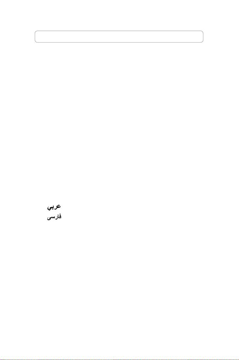
1.1.1 Intel LGA775 Socket
1. LocatetheCPUsocketonthe
2. Release the retention tab and lift
motherboard.
theloadplatewithyourthumb.
Then push the PnP cap from the
load plate window to remove
To prevent damage to the socket
pins, do not remove the PnP cap
Pick and Place Cap (PnP Cap)
unlessyouareinstallingaCPU.
4. Make sure that the gold triangle
3. Position the CPU over the socket.
is on the bottom‑left corner of the
socket.
4
Chapter1: QuickStart
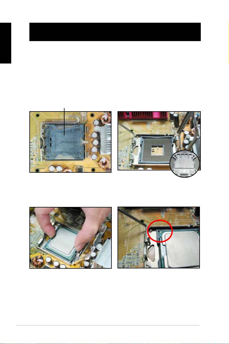
5. FitthesocketalignmentkeyintotheCPUnotch.
English
6. Close the load plate, then push the load lever until it snaps into the retention
tab.
TheCPUtsinonlyonecorrect
orientation.DONOTforcethe
CPU into the socket to prevent
bending the connectors on the
socket and damaging the CPU!
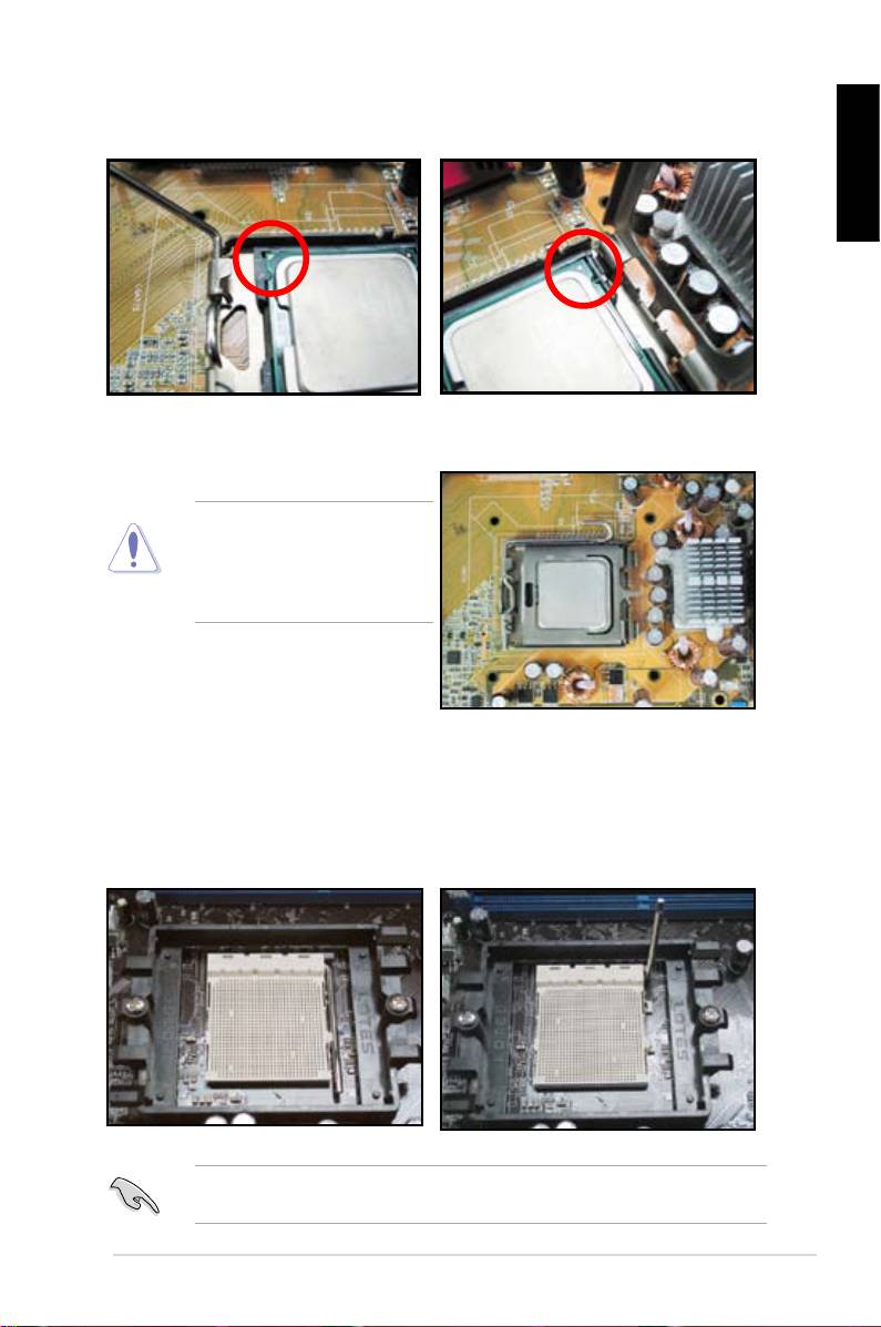
1.1.2 AMD AM2 Socket
1. LocatetheCPUsocketonthe
2. Unlockthesocketbypressingthe
motherboard.
leversideways,thenliftituptoa
90º angle.
Makesurethatthesocketleverisliftedupto90ºangle;otherwise,theCPUwill
nottincompletely.
ASUS Motherboard installation guide
5
English
3. Position the CPU above the socket
4. WhentheCPUisinplace,push
such that the CPU corner with the
down the socket lever to secure the
gold triangle matches the socket
CPU. The lever clicks on the side tab
corner with a small triangle.
to indicate that it is locked.
CarefullyinserttheCPUintothe
socketuntilittsinplace.
TheCPUtsinonlyonecorrectorientation.DONOTforcetheCPUintothe
socket to prevent bending the connectors on the socket and damaging the CPU!
1.2 Installing the heatsink and fan
ToinstalltheCPUheatsinkandfan:
1. SelectanIntel-certiedor
AMD-certiedheatsinkandfanassemblybasedonyour
motherboard.Thereare3-pin(left)and4-pin(right)fanconnectors.OnlyCPUfans
with4-pinconnectorssupportsASUSQ-Fantechnology.
6
Chapter1: QuickStart
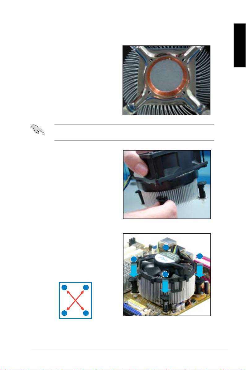
For Intel-certied heatsink:
2. Some heatsinks will come with
thermal paste pre‑applied. If so,
English
do not scrape it off and remove
theprotectivelmonlybefore
installation. If not, before installing
theheatsink,applyseveraldropsof
thermal paste to the exposed area
of the CPU that the heatsink will be
in contact with. Make sure that it is
spreadinaneventhinlayer.
Topreventcontaminatingthepaste,doNOTspreadthepastewithyournger
directly.
3. Orient each fastener with the
narrow end of the groove pointing
outward.
4. Push down two fasteners at a time
in a diagonal sequence to secure
B
theheatsinkandfanassemblyin
place.
A
A
B
A
B
B
A
ASUS Motherboard installation guide
7
English
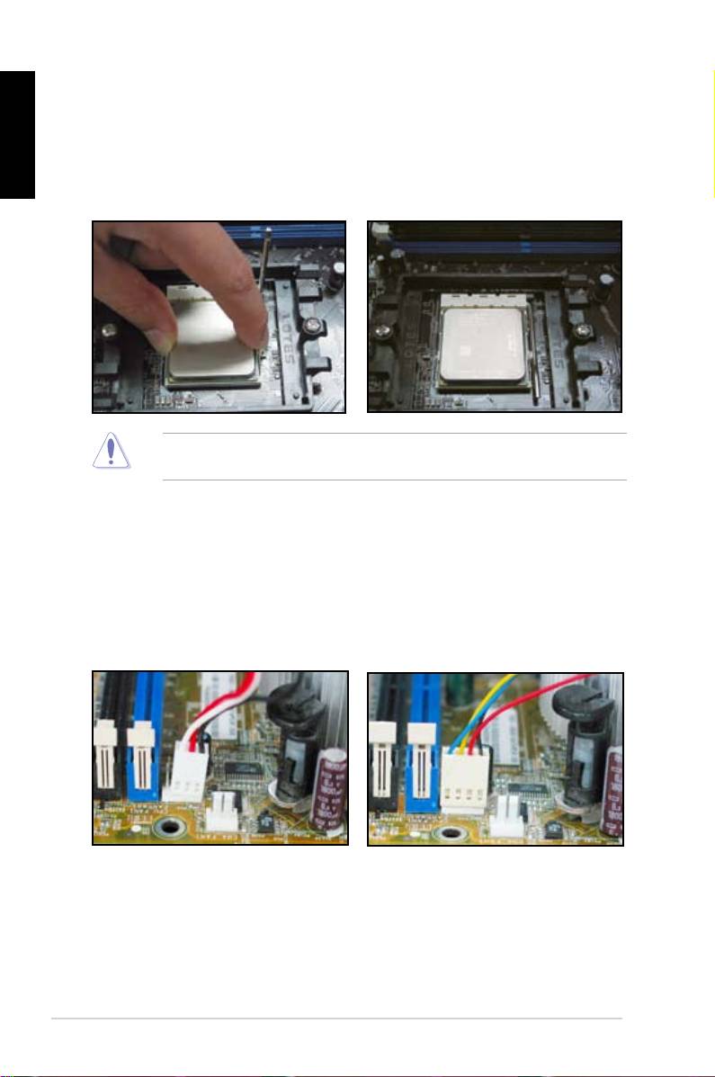
5. Connect the CPU fan cable to the
corresponding connector on the
motherboard.
DONOTforgettoconnecttheCPUfanconnector!Hardwaremonitoring
errorscanoccurifyoufailtoplugthisconnectorandwesuggestyouusean
omnidirectional heatsink to gain the maximum heat dissipation area.
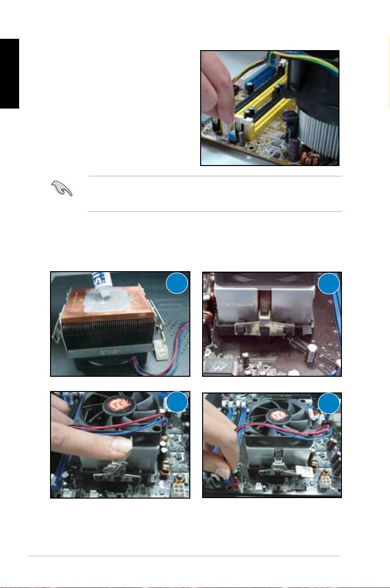
For AMD-certied heatsink:
FollowtheinstructionsbelowtoinstallanAMD-certiedheatsink.
1
2
3
4
8
Chapter1: QuickStart
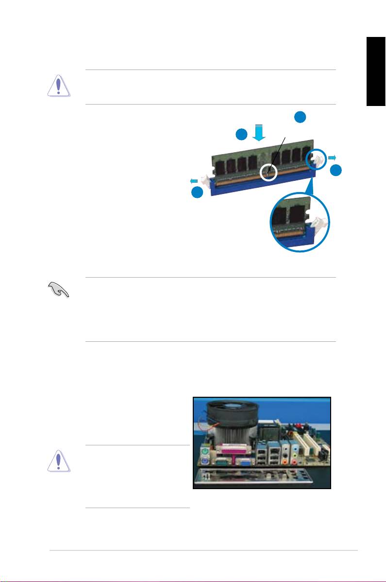
1.3 Installing a DIMM
UnplugthepowersupplybeforeaddingorremovingDIMMsorother
English
systemcomponents.Failuretodosocancauseseveredamagetoboththe
motherboard and the components.
2
ToinstallaDIMM:
DDR2 DIMM notch
3
1. UnlockaDIMMsocketby
pressing the retaining clips
outward.
1
2. AlignaDIMMonthesocket
suchthatthenotchontheDIMM
1
matches the break on the socket.
3. FirmlyinserttheDIMMintothe
socket until the retaining clips
snapbackinplaceandtheDIMM
isproperlyseated.
Unlocked retaining clip
• ADDR2DIMMiskeyedwithanotchsothatittsinonlyonedirection.Do
NOTforceaDIMMintoasockettoavoiddamagingtheDIMM.
• ToinstalltwoormoreDIMMs,refertotheuserguidebundledinthe
motherboard package.
• Refertotheuserguideforqualiedvendorlistsofthememorymodules.
1.4 Installing the motherboard
1. I/O ports differ with motherboards.
Use and install the rear I/O shield
that comes with the motherboard
packageonly.
Some sharp edges and points
mightcausephysicalinjury.We
recommendyouputoncutor
puncture resistant gloves before
motherboard and I/O shield
installation.
ASUS Motherboard installation guide
9
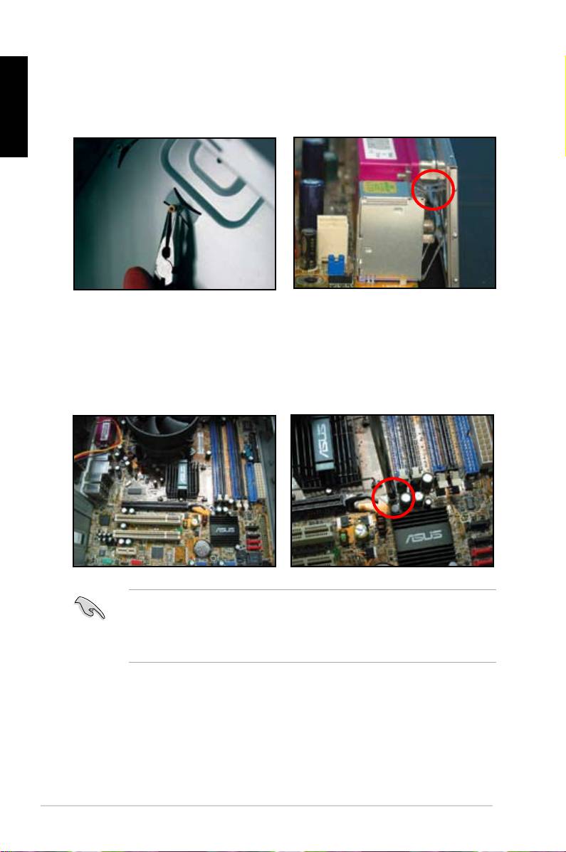
English
2. Install the standoffs to the matched
3. TheI/Oshieldedgespringsmay
screw holes on the metal plate.
damage the I/O ports. Be cautious
when installing the I/O shield.
5. Insertandlooselytighteneach
4. Position the I/O side of the
screwinadiagonalsequencerst.
motherboard toward the rear of the
After all the screws have been
chassis and place the motherboard
inserted, drive the screws until
into the chassis.
theyarenger-tight.
• Youmayremovethemetalslotcoversfortheexpansioncardsattheback
of the chassis before installig the motherboard. For some chassis models, it
mightbedifculttoremovetheexpansionslotcoveraftertheinstallation.
• DONOTover-tightenthescrews.Doingsomaydamagethemotherboard.
10
Chapter1: QuickStart
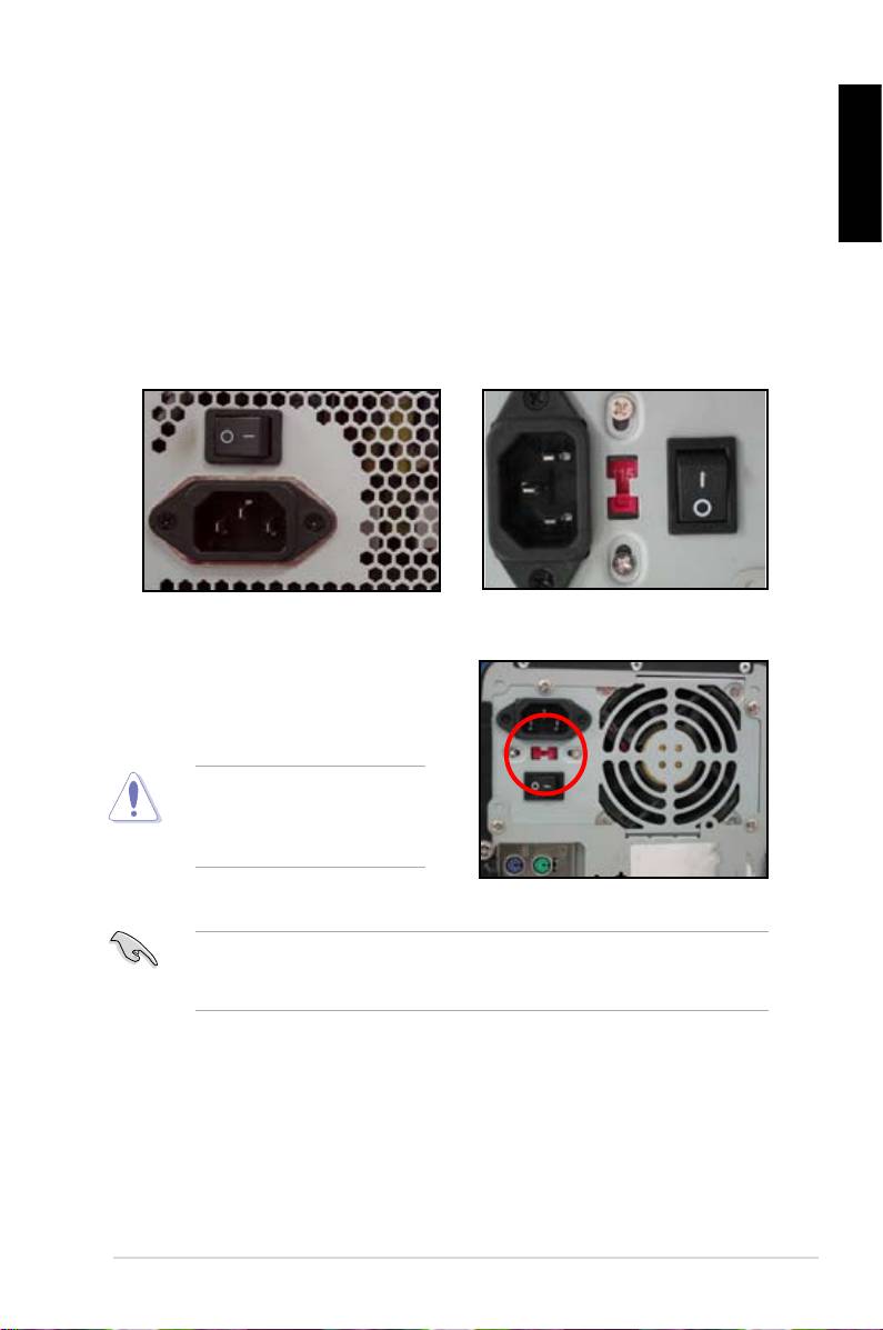
1.5 Installing the power supply unit
Therearetwokindsofcommonly-usedpowersupplyunits.OneiswithActive
Power Factor Correction (PFC) and the other with passive PFC.
English
1. Selectapowersupplyunit.
Power supply with active PFC:
Power supply with passive PFC:
ActivePFCautomaticallycorrects
Passive PFC requires user to
the AC input voltage.
manuallyadjusttheACinput
voltage.
2. Ifyouareusingapowersupply
withpassivePFC,adjusttothe
correctACinputvoltageinyour
area.
Failuretoadjustthepower
supplytothecorrectACinput
volagewillseriouslydamage
thesystem.
Usepowersupplyunitswithsafetycerticationonly.Usingunstablepower
supplyunitscandamageyourmotherboardandothercomponents.Refertothe
userguideforpowersupplyunitsthatmeetthemotherboardrequirements.
ASUS Motherboard installation guide
11
English
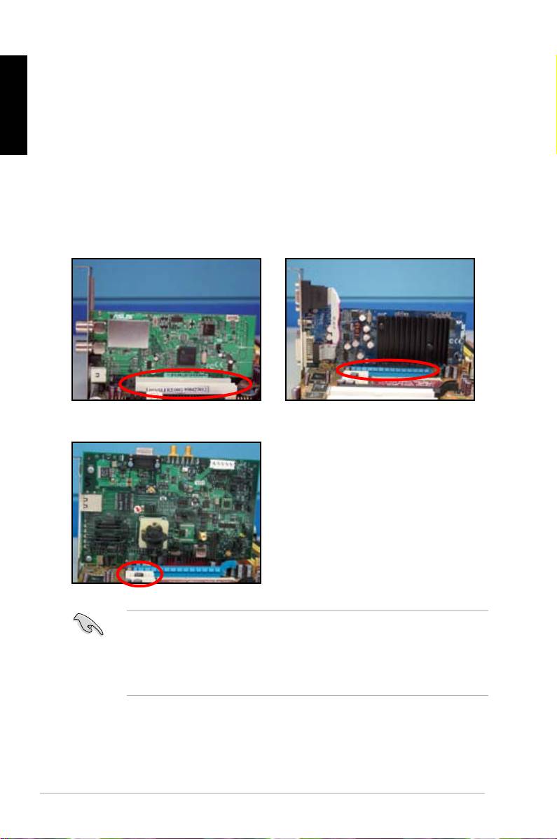
1.6 Installing an expansion card
Toinstallanexpansioncard:
1. Removethemetalslotcoveroppositetheexpansioncardslotwhereyou
wish to install an expansion card.
2. Installtheexpansioncardandmakesurethatitisproperlyseatedontheslot.
3. Screw to secure the card on the slot.
4. Repeat the previous steps to install another expansion card.
PCI card PCIE x16 card
PCIE x1 card
• Refertothecarddocumentationforthecardcongurationdetails,andto
the motherboarduserguideincaseyou needtoconfigureanyjumpers
after installing the expansion card.
• Refer to the motherboard user guide for the instructions of the expansion
card signal cable connection.
12
Chapter1: QuickStart
1.7 Installing disk drives
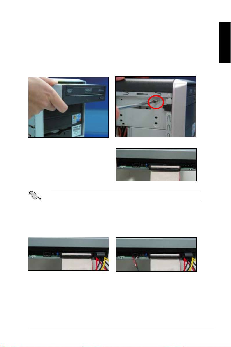
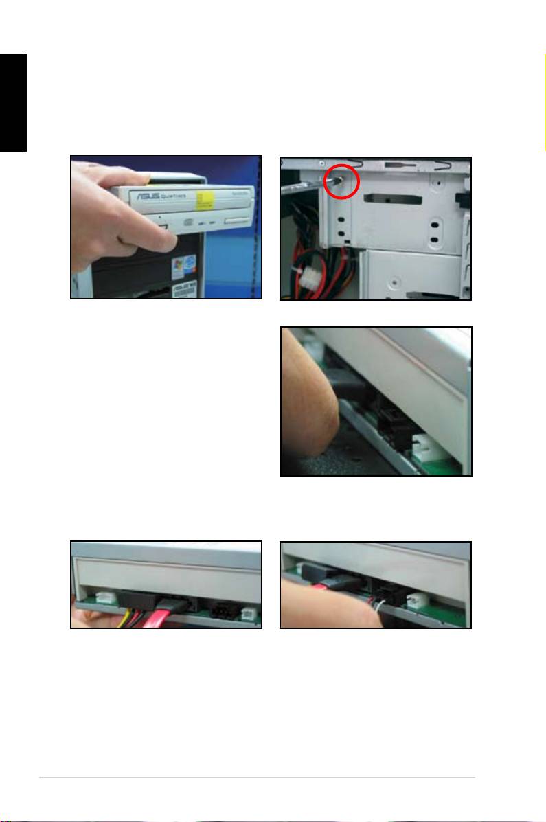
1.7.1 PATA optical disk drive
English
1. Removethedummycoverand
2. Align the screws holes and secure
slide the optical disk drive into the
the disk drive with screws.
bay.
3. OrientandplugtheIDEcableinto
the optical drive. The red stripe on
theIDEcableisthepin1endand
should match the dimple marking
Pin1 on the optical drive.
IDEcablesaredummy-proof.NeverforcetheIDEcableintotheconnector.
4. Connect the 4‑pin power cable to
5. Attach the audio cable to the
the optical drive.
connector on the optical drive.
ASUS Motherboard installation guide
13
English
1.7.2 SATA optical disk drive
1. Removethedummycoverand
2. Align the screws holes and secure
slide the optical disk drive into the
the disk drive with screws.
bay.
3. Orient and plug the SATA cable into
the optical drive. SATA cables are
dummy-proof.NeverforceaSATA
cable into the connector.
4. Connect the SATA power cable to
5. Attach the audio cable to the
the the optical drive.
connector on the optical drive.
14
Chapter1: QuickStart
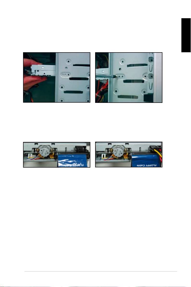
1.7.3 Floppy disk drive
1. Removethedummycoverand
2. Align the screws holes and secure
inserttheoppydiskdriveintothe
the disk drive with screws.
English
bay.
3. Orientandplugtheoppyinterface
4. Connecttheoppypowercableto
cableintotheoppydiskdrive.The
the connector at the back of the
red stripe on the cable is the pin1
oppydiskdrive.
end and should match pin1 on the
oppydiskdrive.
ASUS Motherboard installation guide
15
English
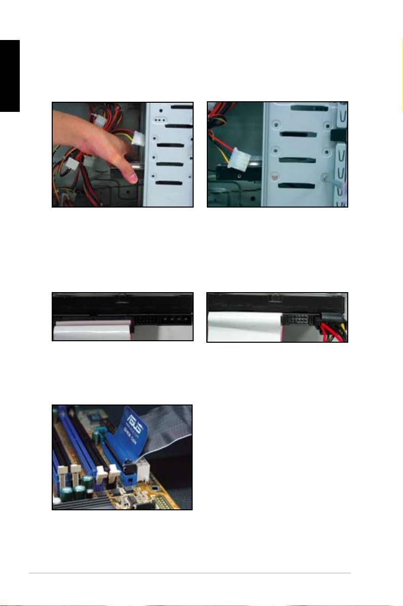
1.7.4 PATA hard disk drive
1. Insert the PATA hard disk drive into
2. Align the screws holes and secure
thebay.
the disk drive with screws.
3. Orient and connect the signal cable
4. Connect the 4‑pin power cable to
to the hard disk drive. The red stripe
the connector at the back of the
on the cable is the pin1 end. Match
hard disk drive.
thedummy-proofnotchanddonot
force the cable into the connector.
5. Attch the other end of the signal
cable to the corresponding slot on
the motherboard.
16
Chapter1: QuickStart
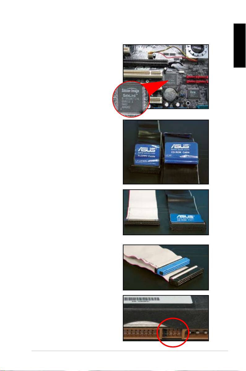
Notes for installing PATA hard disk drive
• Ifyouroperatingsystemisinstalled
totheharddiskdrivecontrolledby
English
theRAIDorothercontrollers,you
have to install the controller driver
totheharddiskrst.
• The cables are designed with pull
tabs.Justeasilyinstallthedisk
drives based on the cable labels.
To prevent damaging the pins,
disconnectthecablebypullingthe
the cable tabs.
• TherearetwocablesforATAIDE
disk drives, the newer 80‑wire
(right) and the older 40‑wire (left)
cables. For ATA66/100/133 disk
drives,onlythe80-wirecablecan
offer a better perfermance. The
40-wirecablesareusuallyforthe
optical drives.
• The cable connector is color‑
coded. The blue one is for the host
connector,andtheblack/grayone
isfortheprimary/secondarydisk
drive.
• WhenconnectingtwoIDEdevices,
youhavetosetthejumpersto
different position, one in master
andoneinslave.Ifyouareusing
80-wirecable,youcanusethe
cableselectstyle.
ASUS Motherboard installation guide
17
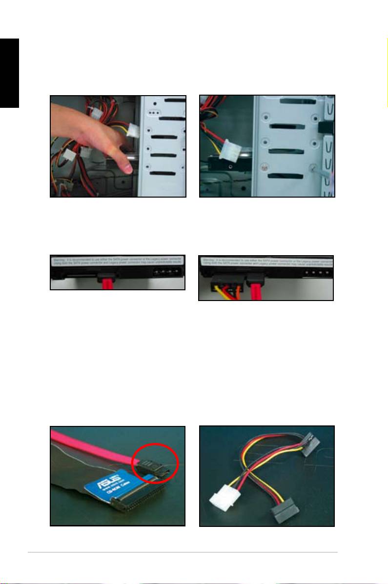
1.7.5 SATA hard disk drive
English
1. Insert the SATA hard disk drive into
2. Align the screws holes and secure
thebay.
the disk drive with screws.
3. Orient and connect the SATA cable
4. Connect the SATA power cable to
to the hard disk drive. The cable can
the connector at the back of the
onlytinonedirection.
hard disk drive.
Notes for installing SATA hard disk drive
• Serial ATA (SATA) interface
• The SATA power cable connector
provides higher data transmission
is different from the traditional
speed,and better voltage tolerance.
4‑pin power connector. ASUS
The narrow design of the SATA
motherboard bundles power adopter
cable also solves cabling issues
cablesforyouincaseyourpower
andallowsbetterairowinthe
supplyunitdoesnotincludethis
chassis.
new connector.
18
Chapter1: QuickStart
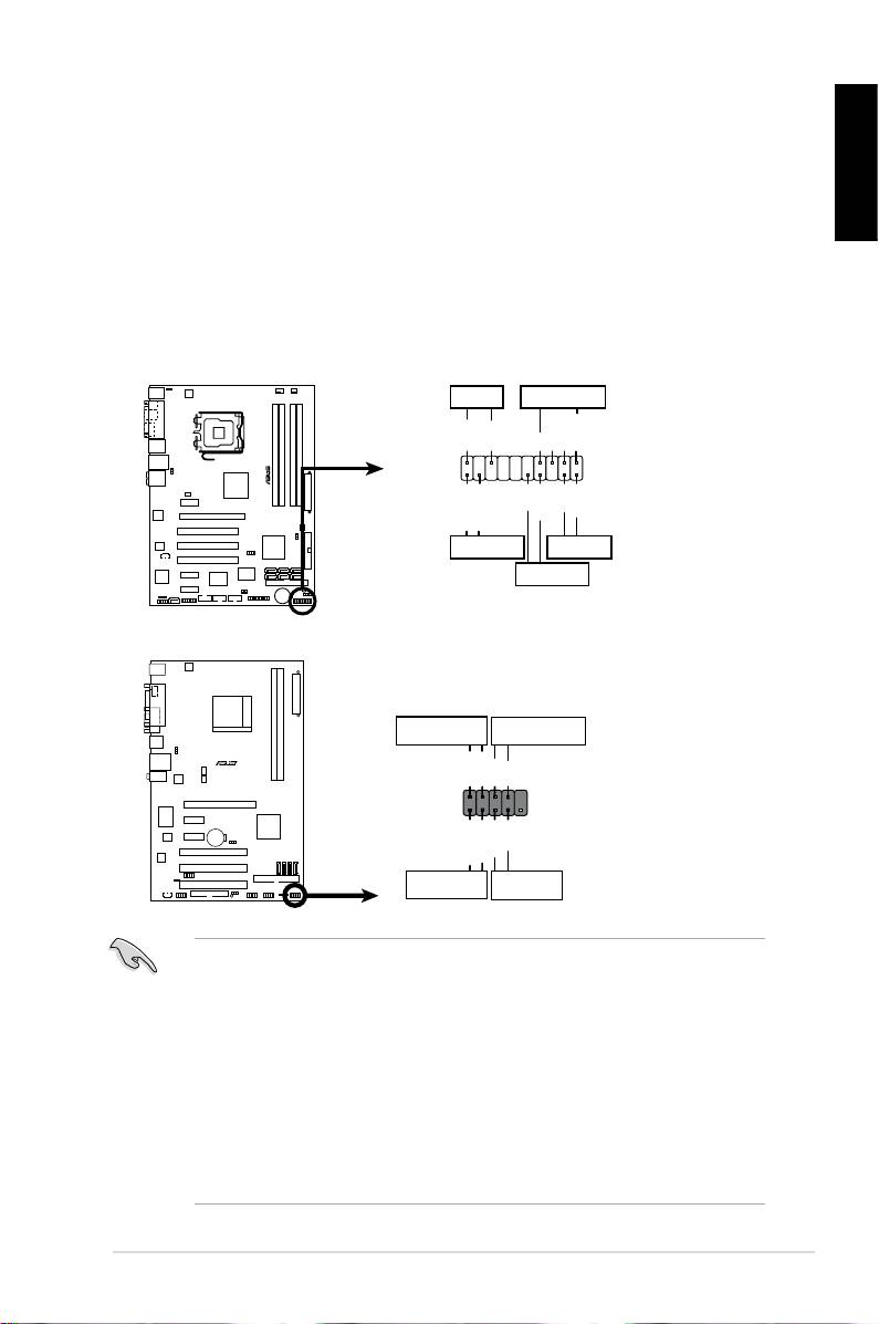
1.8 Front panel cables
Toconnectthefrontpanelcables:
• RESET (Reset Switch)
English
• PLED(PowerLED)
• PWRSW(PowerSwitch)
• IDE_LED(IDEHardDiskActiveLED)
• SPEAKER (Speaker Connector)
ASUS Motherboard installation guide
19
PWRLED PWRBTN
M2N-X
PLED+
PLED-
PWR
GNDReset
F_PANEL
Ground
IDELED+
IDELED-
HD LED RESET
PLED SPEAKER
P5B-E
PLED+
PLED-
+5V
Ground
Ground
Speaker
®
PANEL
PWR
Reset
Ground
Ground
IDE_LED+
IDE_LED-
IDE_LED
RESET
PWRSW
*
Requires an ATX power supply.
20-8 pin front panel connector
PIN1
PIN1
10-1 pin front panel connector
• Thefrontpanelcablesofyourchassismaydifferwithmodelsordesigns.
Connect these connectors to the motherboard according to the label.
• IftheLEDsdonotlightupandthepinloctioniscorrect,youmightmisplace
thegroundpinswiththesignalpins.Usuallythewhitewirestandsforthe
ground pins and the color‑coded wire for the signal pins.
• TheSPEAKER,RESETandPWRSWfrontpanelcableshavenospecic
orientation,whileIDE_LEDandPLEDcablesdo.Connectthethecable
PIN1 to the connector PIN1 on the motherboard.
• Thefrontpanelconnectorvarieswithyourmotherboardmodel,refertothe
user guide for more information.
