Asus T5-P5G41E: инструкция
Раздел: Компьютерная техника, комплектующие, аксессуары
Тип: Мультимедийный Компьютер
Инструкция к Мультимедийному Компьютеру Asus T5-P5G41E
English
T5-Series
ASUS PC (Desktop Barebone)
Installation manual
Download the latest manual from the ASUS website: www.asus.com
u5335_T5_series_qsg.indb 1 1/29/10 3:55:42 PM
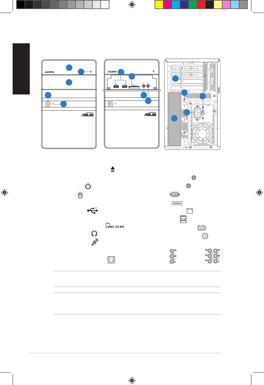
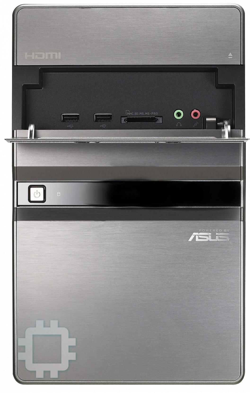
Front/Rear panel features
English
1. Optical drive bay cover
12.** Voltage selector switch
2. Optical drive eject button ( )
13. Power connector
3. Front I/O ports cover
14.* • PS/2 keyboard port ( )
4. Power button ( )
• PS/2 mouse port ( )
• VGA port ( )
5. HDD LED ( )
(lights up when
the hard disk drive operates)
• HDMI port ( )
6. USB 2.0 ports ( )
• LAN (RJ-45) port ( )
7. MultiMediaCard / Secure Digital /
• USB 2.0 ports ( )
Memory Stick card slot ( )
• 6-pin IEEE 1394a port ( )
8. Headphone port ( )
• Coaxial S/PDIF Out port ( )
9. Microphone port ( )
•Audioportscongurations:
10. Expansion slot metal brackets
11.* Optical S/PDIF Out port ( )
• 6-channel
2 Installation manual
L
IN
IN
E
FR
O
N
T
M
IC
IN
• 8-channel
C
BA
T
S
S
R
L
IN
IN
E
R
S
E
P
A
K
R
FR
O
N
T
S
S
P
ID
K
E
M
IC
IN
NOTE: *The front/rear panel ports and their locations may vary, depending on the
model of your system. For detailed descriptions, refer to the system User Guide.
NOTE:**Thesystem’spowersupplyunithasa115V/230Vvoltageselectorswitch
located beside the power connector. Use this switch to select the appropriate system
input voltage according to the voltage supply in your area.
SPDIF OUT
SATA
Front (Close)
Front (Slide open)
Rear
1
2
6
7
10
3
11
4
8
12
9
5
13
14
u5335_T5_series_qsg.indb 2 1/29/10 3:55:54 PM
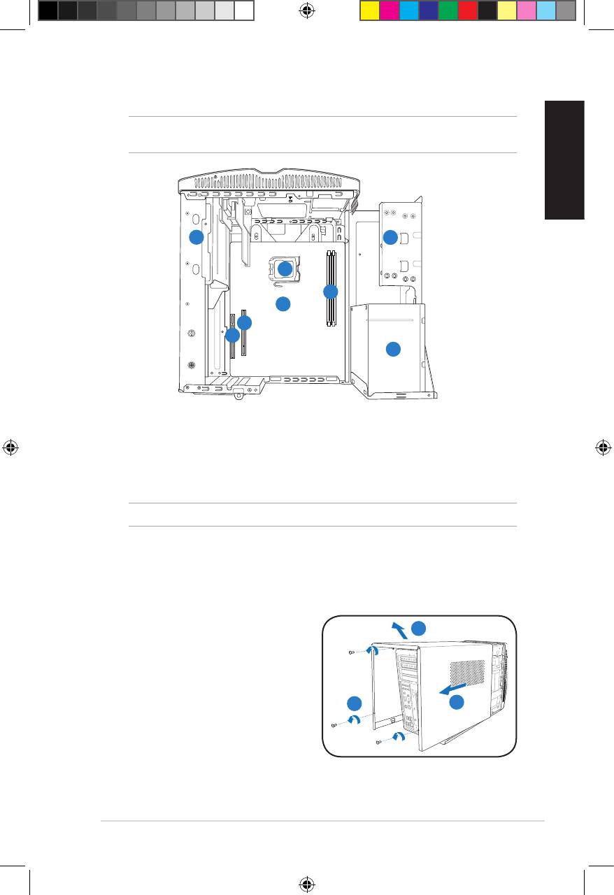
Internal components
NOTE: The illustration below shows the internal view of the system when you remove
the cover and lift the power supply unit.
English
1
2
5
4
6
7
8
3
1. 5.25-inch optical drive cage
5. CPU socket
2. 3.5-inch hard disk drive cage
6.* ASUS motherboard
3. Power supply unit
7. PCI Express x16 slot
4. DIMM sockets
8. PCI slot
NOTE: *Refer to the system User Guide for motherboard details.
Removing the cover
1. Remove the three cover screws on
3
the rear panel. Keep the screws for
later use.
2. Pull the cover toward the rear panel.
3. Lift the cover, then set it aside.
1
2
3Installation manual
u5335_T5_series_qsg.indb 3 1/29/10 3:55:55 PM
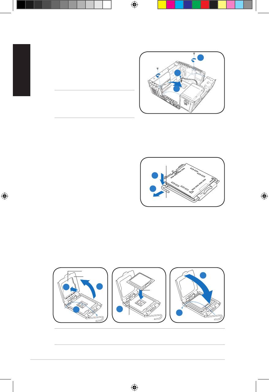
Lifting the power supply unit
1. Locate and remove the two screws.
English
1
2. Remove the 4-pin ATX 12V power
cable.
2
3. Lift the PSU in the direction of the
arrow to a 90º angle.
3
CAUTION: When removing the PSU,
makesuretoholdorsupportitrmly.
The unit might accidentally drop and
damage the other system components.
Installing a CPU
®
Installing an Intel
CPU
1. Locate the CPU socket on the
Retention tab
motherboard.
2. Press the load lever with your
2A
thumb (2A), then move it to the left
(2B) until it is released from the
2B
retention tab.
Load lever
3. Lift the load lever in the direction of
the arrow to a 135º angle.
4. Lifttheloadplatewithyourthumbandforengertoa100ºangle(4A),then
push the PnP cap from the load plate window to remove (4B).
5. Position the CPU over the socket, making sure that the gold triangle is on the
bottom-left corner of the socket. Fit the socket alignment key into the CPU
notch.
6. Close the load plate (6A), then push the load lever (6B) until it snaps into the
retention tab.
PnP cap
Load plate
6A
Gold
4B
4A
triangle
mark
3
5
6B
Alignment key
CAUTION: Incorrect installation of the CPU into the socket may bend the pins and
severely damage the CPU.
4 Installation manual
u5335_T5_series_qsg.indb 4 1/29/10 3:55:58 PM
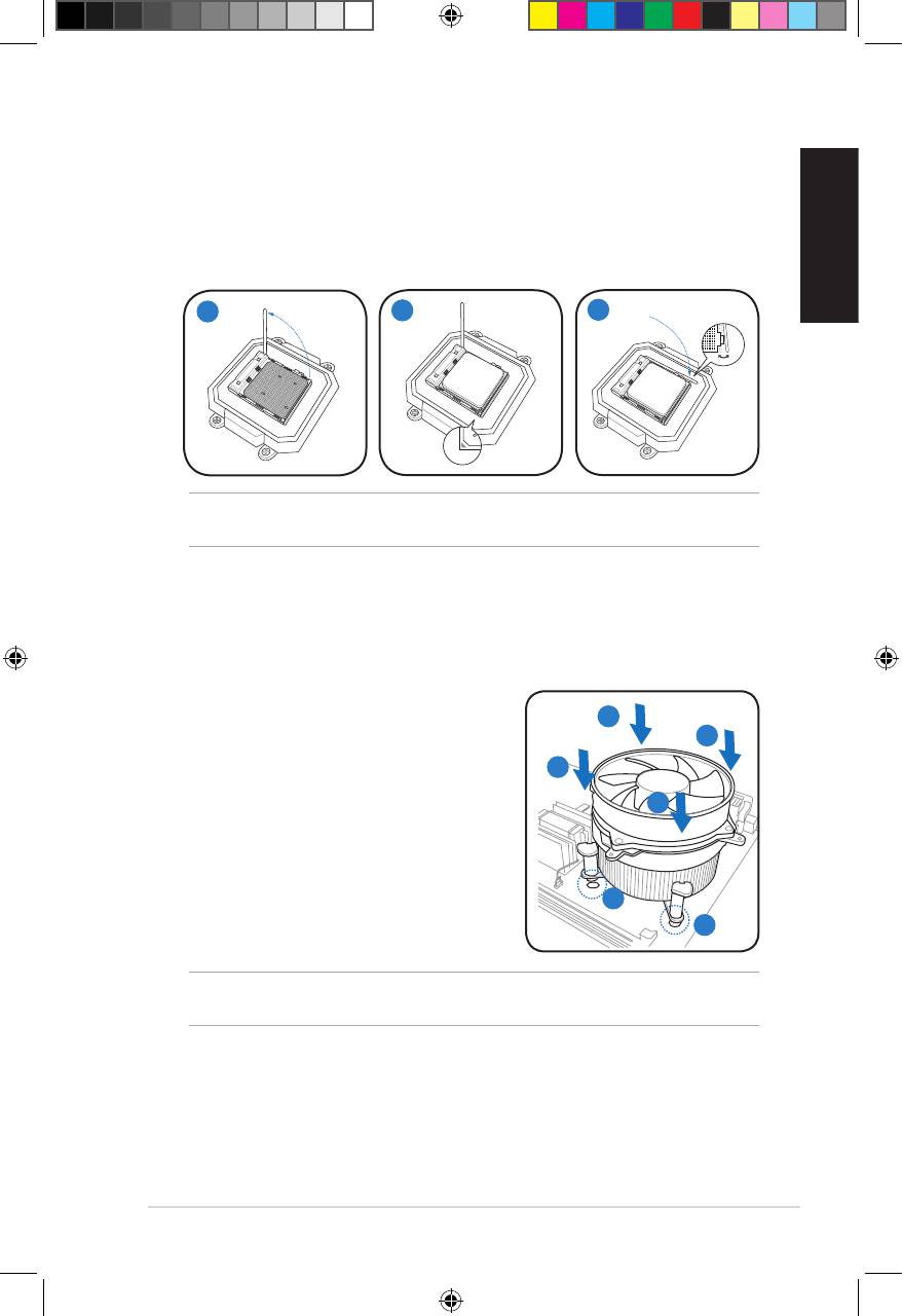
Installing an AMD CPU
1. Locate the CPU socket, then lift the socket lever to a 90º angle.
2. Install the CPU to the socket, making sure that the CPU corner with the gold
triangle matches the socket corner with a small triangle.
3. Push down the socket lever to secure the CPU.
English
1
2
3
CAUTION: Incorrect installation of the CPU into the socket may bend the pins and
severely damage the CPU.
Installing the CPU fan and heatsink assembly
®
Installing an Intel
CPU heatsink and fan
1. Place the heatsink on top of the installed
A
CPU, making sure that the four fasteners
B
match the holes on the motherboard.
B
2. Push down two fasteners at a time in a
diagonal sequence to secure the heatsink
A
and fan assembly in place.
3. When the fan and heatsink assembly is in
place, connect the CPU fan cable to the
connector on the motherboard.
1
1
CAUTION. Do not forget to connect the CPU fan connector! Hardware monitoring error
can occur if you fail to plug this connector.
5Installation manual
u5335_T5_series_qsg.indb 5 1/29/10 3:56:01 PM
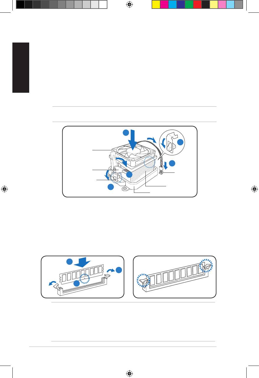
Installing an AMD CPU heatsink and fan
English
1. Place the heatsink on top of the installed CPU.
2. Attach one end of the retention bracket to the retention module base.
3. Attach the other end of the retention bracket (near the retention bracket lock)
to the retention module base until it clicks in place.
4. Push down the retention bracket lock on the retention mechanism to secure
the fan and heatsink to the module retention module base.
5. Connect the CPU fan cable to the connector on the motherboard.
CAUTION. Do not forget to connect the CPU fan connector! Hardware monitoring error
can occur if you fail to plug this connector.
1
2
CPU fan
5
Retention
CPU fan
bracket lock
4
connector
Retention bracket
3
CPU heatsink
Retention module base
Installing a DIMM
1. Locate the DIMM sockets in the motherboard.
2. Unlock a DIMM socket by pressing the retaining clips outward.
3. Align a DIMM on the socket such that the notch on the DIMM matches the
break on the socket.
4. Push the DIMM to the socket until the retaining clips snap inward.
4
2
3
CAUTION:
• Unplug the power supply before adding or removing DIMMs. Failure to do so may
cause damage to the motherboard and/or components.
• ADDRDIMMiskeyedwithanotchsothatittsinonlyonedirection.Donotforce
a DIMM into a socket to avoid damaging the DIMM.
6 Installation manual
u5335_T5_series_qsg.indb 6 1/29/10 3:56:03 PM
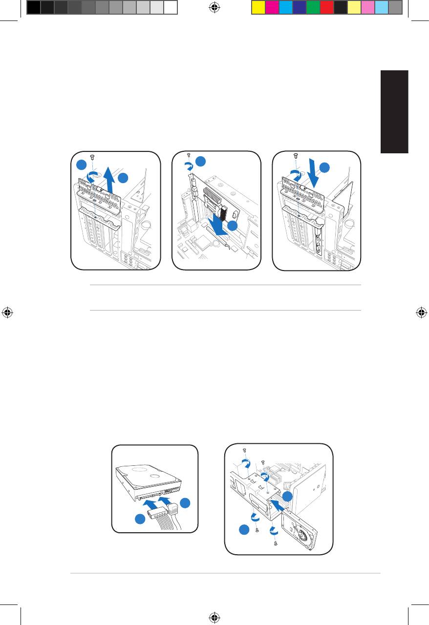
Installing an expansion card
1. Locate and remove one metal bracket lock screw.
2. Remove the metal bracket lock.
3. Alignthecardconnectorwiththeslot,thenpressrmly.
4. Secure the card with one screw.
English
5. Replace the metal braket lock, then secure it with one screw.
4
1
5
2
3
IMPORTANT. This chassis supports PCI Express x 16 cards with 192mm x 19mm or
smaller dimensions only.
Installing a hard disk drive
1. Connect the SATA signal (1A) and power (1B) plugs to the connectors at the
back of the SATA hard disk drives.
2. Locate the HDD tray.
3. Insert a hard disk drive (with the HDD PCB facing the top of the chassis) to
the tray, then secure it with four screws.
4. Connect the SATA signal cable to the SATA connector on the motherboard, and
tighten all the cables with the plastic coils.
SATA
3
1A
1B
3
7Installation manual
u5335_T5_series_qsg.indb 7 1/29/10 3:56:06 PM
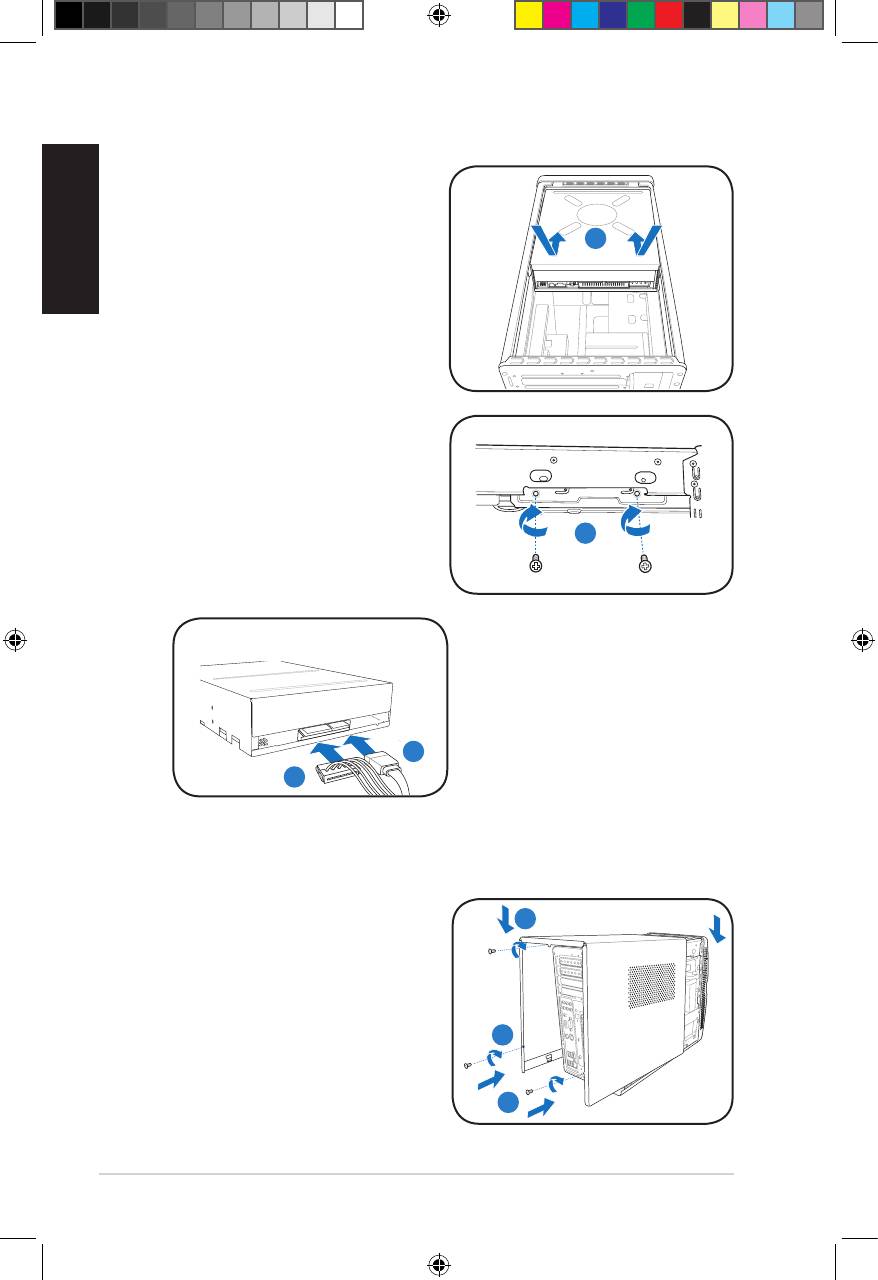
Installing an optical drive
1. Place the chassis upright.
English
2. Insert the SATA optical drive to
the upper 5.25 in drive bay, then
2
carefully push the drive until its
screw holes align with the holes on
the bay.
3. Secure the optical drive with four
screws on both sides of the bay.
4. Connect the SATA signal (4A) and
power plugs (4B) to the connectors
at the back of the SATA drive.
3
SATA
4A
4B
Reinstalling the cover
1. Fit the cover tabs with the chassis rail
1B
and the front panel tabs (1A), then
lower the rear edge of the cover as
shown (1B).
2. Secure the cover with three screws.
2
1A
8 Installation manual
u5335_T5_series_qsg.indb 8 1/29/10 3:56:09 PM


