Asus A8V-VM: инструкция
Раздел: Бытовая, кухонная техника, электроника и оборудование
Тип: Автоответчик
Инструкция к Автоответчику Asus A8V-VM

A8V-VM
Motherboard

E2421
Second Edition
January 2006
Copyright © 2006 ASUSTeK COMPUTER INC. All Rights Reserved.
No part of this manual, including the products and software described in it, may be reproduced,
transmitted, transcribed, stored in a retrieval system, or translated into any language in any form
or by any means, except documentation kept by the purchaser for backup purposes, without the
express written permission of ASUSTeK COMPUTER INC. (“ASUS”).
Product warranty or service will not be extended if: (1) the product is repaired, modied or
altered, unless such repair, modication of alteration is authorized in writing by ASUS; or (2) the
serial number of the product is defaced or missing.
ASUS PROVIDES THIS MANUAL “AS IS” WITHOUT WARRANTY OF ANY KIND, EITHER EXPRESS
OR IMPLIED, INCLUDING BUT NOT LIMITED TO THE IMPLIED WARRANTIES OR CONDITIONS OF
MERCHANTABILITY OR FITNESS FOR A PARTICULAR PURPOSE. IN NO EVENT SHALL ASUS,
ITS DIRECTORS, OFFICERS, EMPLOYEES OR AGENTS BE LIABLE FOR ANY INDIRECT, SPECIAL,
INCIDENTAL, OR CONSEQUENTIAL DAMAGES (INCLUDING DAMAGES FOR LOSS OF PROFITS, LOSS
OF BUSINESS, LOSS OF USE OR DATA, INTERRUPTION OF BUSINESS AND THE LIKE), EVEN IF ASUS
HAS BEEN ADVISED OF THE POSSIBILITY OF SUCH DAMAGES ARISING FROM ANY DEFECT OR
ERROR IN THIS MANUAL OR PRODUCT.
SPECIFICATIONS AND INFORMATION CONTAINED IN THIS MANUAL ARE FURNISHED FOR
INFORMATIONAL USE ONLY, AND ARE SUBJECT TO CHANGE AT ANY TIME WITHOUT NOTICE, AND
SHOULD NOT BE CONSTRUED AS A COMMITMENT BY ASUS. ASUS ASSUMES NO RESPONSIBILITY
OR LIABILITY FOR ANY ERRORS OR INACCURACIES THAT MAY APPEAR IN THIS MANUAL,
INCLUDING THE PRODUCTS AND SOFTWARE DESCRIBED IN IT.
Products and corporate names appearing in this manual may or may not be registered
trademarks or copyrights of their respective companies, and are used only for identication or
explanation and to the owners’ benet, without intent to infringe.
ii

Table of contents
Notices ................................................................................................ vi
Safety information ..............................................................................vii
A8V-VM specications summary ........................................................viii
Chapter 1: Product introduction
1.1 Welcome! .............................................................................. 1-2
1.2 Package contents ................................................................. 1-2
1.3 Special features .................................................................... 1-3
1.3.1 Product highlights ................................................... 1-3
1.3.2 Innovative ASUS features ...................................... 1-4
1.4 Before you proceed .............................................................. 1-5
1.5 Motherboard overview .......................................................... 1-6
1.5.1 Motherboard layout ................................................ 1-6
1.5.2 Placement direction ................................................ 1-6
1.5.3 Screw holes ............................................................. 1-7
1.6 Central Processing Unit (CPU) .............................................. 1-8
1.6.1 Overview ................................................................. 1-8
1.6.2 Installing the CPU .................................................... 1-8
1.6.3 Installing the heatsink and fan .............................. 1-10
1.7 System memory .................................................................. 1-12
1.7.1 Overview ............................................................... 1-12
1.7.2 Memory congurations ......................................... 1-12
1.7.3 Installing a DIMM ................................................... 1-15
1.7.4 Removing a DIMM .................................................. 1-15
1.8 Expansion slots ................................................................... 1-16
1.8.1 Installing an expansion card .................................. 1-16
1.8.2 Conguring an expansion card .............................. 1-16
1.8.3 PCI slots ................................................................ 1-18
1.8.4 PCI Express x1 slot ............................................... 1-18
1.8.5 PCI Express x16 slot ............................................. 1-18
1.9 Jumpers .............................................................................. 1-19
1.10 Connectors ......................................................................... 1-21
1.10.1 Rear panel connectors .......................................... 1-21
1.10.2 Internal connectors ............................................... 1-22
iii
Table of contents
Chapter 2: BIOS setup
2.1 Managing and updating your BIOS ........................................ 2-2
2.1.1 Creating a bootable oppy disk .............................. 2-2
2.1.2 ASUS EZ Flash utility ............................................... 2-3
2.1.3 AFUDOS utility ........................................................ 2-4
2.1.4 ASUS CrashFree BIOS 2 utility ................................ 2-6
2.1.5 ASUS Update utility ................................................ 2-8
2.2 BIOS setup program ............................................................ 2-11
2.2.1 BIOS menu screen ................................................. 2-12
2.2.2 Menu bar ............................................................... 2-12
2.2.3 Navigation keys ..................................................... 2-12
2.2.4 Menu items ........................................................... 2-13
2.2.5 Sub-menu items .................................................... 2-13
2.2.6 Conguration elds ............................................... 2-13
2.2.7 Pop-up window ...................................................... 2-13
2.2.8 Scroll bar ............................................................... 2-13
2.2.9 General help .......................................................... 2-13
2.3 Main menu ........................................................................... 2-14
2.3.1 System Time ......................................................... 2-14
2.3.2 System Date ......................................................... 2-14
2.3.3 Legacy Diskette A ............................................... 2-14
2.3.4 Primary and Secondary IDE Master/Slave;
First and Second SATA ......................................... 2-15
2.3.5 System Information............................................... 2-16
2.4 Advanced menu .................................................................. 2-17
2.4.1 JumperFree Conguration ..................................... 2-17
2.4.2 CPU Conguration ................................................. 2-18
2.4.3 Chipset ................................................................. 2-19
2.4.4 Onboard Devices Conguration ............................. 2-23
2.4.5 PCI PnP .................................................................. 2-24
2.5 Power menu ........................................................................ 2-26
2.5.1 Suspend Mode ...................................................... 2-26
2.5.2 Repost Video on S3 Resume ................................ 2-26
iv
Table of contents
2.5.3 ACPI 2.0 Support ................................................. 2-26
2.5.4 ACPI APIC Support ................................................ 2-26
2.5.5 APM Conguration ................................................ 2-27
2.5.6 Hardware Monitor .................................................. 2-29
2.6 Boot menu .......................................................................... 2-30
2.6.1 Boot Device Priority .............................................. 2-30
2.6.2 Boot Settings Conguration ................................. 2-31
2.6.3 Security ................................................................. 2-32
2.7 Exit menu ............................................................................ 2-34
Chapter 3: Software support
3.1 Installing an operating system .............................................. 3-2
3.2 Support CD information ........................................................ 3-2
3.2.1 Running the support CD .......................................... 3-2
3.2.2 Drivers menu ........................................................... 3-3
3.2.3 Utilities menu .......................................................... 3-4
3.2.4 Manual ..................................................................... 3-5
3.2.5 ASUS Contact information ...................................... 3-6
v
Notices
Federal Communications Commission Statement
This device complies with Part 15 of the FCC Rules. Operation is subject to
the following two conditions:
•
This device may not cause harmful interference, and
•
This device must accept any interference received including
interference that may cause undesired operation.
This equipment has been tested and found to comply with the limits for a
Class B digital device, pursuant to Part 15 of the FCC Rules. These limits
are designed to provide reasonable protection against harmful interference
in a residential installation. This equipment generates, uses and can radiate
radio frequency energy and, if not installed and used in accordance with
manufacturer’s instructions, may cause harmful interference to radio
communications. However, there is no guarantee that interference will
not occur in a particular installation. If this equipment does cause harmful
interference to radio or television reception, which can be determined by
turning the equipment off and on, the user is encouraged to try to correct
the interference by one or more of the following measures:
•
Reorient or relocate the receiving antenna.
•
Increase the separation between the equipment and receiver.
•
Connect the equipment to an outlet on a circuit different from that to
which the receiver is connected.
•
Consult the dealer or an experienced radio/TV technician for help.
The use of shielded cables for connection of the monitor to the graphics
card is required to assure compliance with FCC regulations. Changes
or modications to this unit not expressly approved by the party
responsible for compliance could void the user’s authority to operate
this equipment.
Canadian Department of Communications Statement
This digital apparatus does not exceed the Class B limits for radio noise
emissions from digital apparatus set out in the Radio Interference
Regulations of the Canadian Department of Communications.
This class B digital apparatus complies with Canadian ICES-003.
vi
Safety information
Electrical safety
•
To prevent electrical shock hazard, disconnect the power cable from
the electrical outlet before relocating the system.
•
When adding or removing devices to or from the system, ensure that
the power cables for the devices are unplugged before the signal cables
are connected. If possible, disconnect all power cables from the existing
system before you add a device.
•
Before connecting or removing signal cables from the motherboard,
ensure that all power cables are unplugged.
•
Seek professional assistance before using an adapter or extension cord.
These devices could interrupt the grounding circuit.
•
Make sure that your power supply is set to the correct voltage in your
area. If you are not sure about the voltage of the electrical outlet you
are using, contact your local power company.
•
If the power supply is broken, do not try to fix it by yourself. Contact a
qualified service technician or your retailer.
Operation safety
•
Before installing the motherboard and adding devices on it, carefully
read all the manuals that came with the package.
•
Before using the product, make sure all cables are correctly connected
and the power cables are not damaged. If you detect any damage,
contact your dealer immediately.
•
To avoid short circuits, keep paper clips, screws, and staples away from
connectors, slots, sockets and circuitry.
•
Avoid dust, humidity, and temperature extremes. Do not place the
product in any area where it may become wet.
•
Place the product on a stable surface.
•
If you encounter technical problems with the product, contact a
qualified service technician or your retailer.
The symbol of the crossed out wheeled bin indicates that the product
(electrical and electronic equipment) should not be placed in municipal
waste. Check local regulations for disposal of electronic products.
vii
About this guide
This user guide contains the information you need when installing and
conguring the motherboard.
How this guide is organized
This manual contains the following parts:
• Chapter 1: Product introduction
This chapter describes the features of the motherboard and the new
technology it supports. It also lists the hardware setup procedures
that you have to perform when installing system components.
It includes description of the jumpers and connectors on the
motherboard.
• Chapter 2: BIOS setup
This chapter tells how to change system settings through the BIOS
Setup menus. Detailed descriptions of the BIOS parameters are also
provided.
• Chapter 3: Software support
This chapter describes the contents of the support CD that comes
with the motherboard package.
Where to find more information
Refer to the following sources for additional information and for product
and software updates.
1. ASUS websites
The ASUS website provides updated information on ASUS hardware
and software products. Refer to the ASUS contact information.
2. Optional documentation
Your product package may include optional documentation, such as
warranty yers, that may have been added by your dealer. These
documents are not part of the standard package.
viii
Conventions used in this guide
To make sure that you perform certain tasks properly, take note of the
following symbols used throughout this manual.
DANGER/WARNING: Information to prevent injury to yourself
when trying to complete a task.
CAUTION: Information to prevent damage to the components
when trying to complete a task.
IMPORTANT: Instructions that you MUST follow to complete a
task.
NOTE: Tips and additional information to help you complete a
task.
Typography
Bold text Indicates a menu or an item to select
Italics
Used to emphasize a word or a phrase
<Key> Keys enclosed in the less-than and
greater-than sign means that you
must press the enclosed key
Example: <Enter> means that you
must press the Enter or Return key
<Key1> + <Key2> + <Key3> If you must press two or more keys
simultaneously, the key names are
linked with a plus sign (+)
Example: <Ctrl> + <Alt> + <Del>
Command Means that you must type the
command exactly as shown, then
supply the required item or value
enclosed in brackets
Example: At the DOS prompt, type the
command line:
awdash A8VVM.ROM
ix
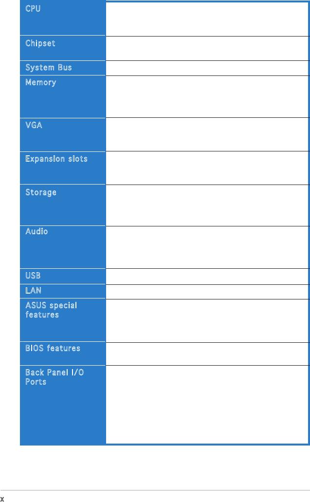
A8V-VM specications summary
®
CPU
Socket 939 for AMD
Athlon™ 64FX/ Athlon™ 64X2/
Athlon™ 64/ Sempron processor
Supports AMD Cool ‘n’ Quiet!™ Technology
®
Chipset
Northbridge: VIA
K8M890
®
Southbridge: VIA
VT8251
System Bus
2000/1600 MT/s
Memory
Dual-channel memory architecture
4 x 184-pin DIMM sockets support unbuffered ECC/
non-ECC DDR 400/333/266 MHz memory modules
Supports up to 4 GB system memory
VGA
Integrated VIA DeltaChrome Graphics Processing Unit
Supports Microsoft DirectX 9.0 (Refer to page 3-5)
Maximum shared mamory of 256 MB
Expansion slots
1 x PCI Express x16 slot
1 x PCI Express x1 slot
2 x PCI slots
®
Storage
VIA
VT8251 South Bridge supports:
- 2 x UltraDMA 133/100/66/33
- 4 x Serial ATA 3Gb/s devices with RAID 0, RAID 1,RAID 0, RAID 1,
RAID 0+1, RAID 5, and JBOD
Audio
ADI AD1986A SoundMAX 6-channel High Denition
Audio CODEC
Supports Jack Sensing Technology
Supports S/PDIF out interface
USB
Supports up to eight USB 2.0 ports
LAN
Realtek RTL8201CL 10/100M LAN PHY
ASUS special
ASUS C.P.R. (CPU Parameter Recall)(CPU Parameter Recall)
features
ASUS MyLogo
ASUS EZ Flash
ASUS CrashFree BIOS 2
BIOS features
4 Mb Flash ROM, AMI BIOS, PnP, DMI2.0, WfM2.0, SM
BIOS 2.3
Back Panel I/O
1 x Parallel port
Ports
1 x Serial port
1 x PS/2 keyboard port
1 x PS/2 mouse port
1 x RJ45 port
4 x USB 2.0/1.1 ports
1 x 6-Channel Audio I/O port
1 x VGA port
(continued on the next page)
x
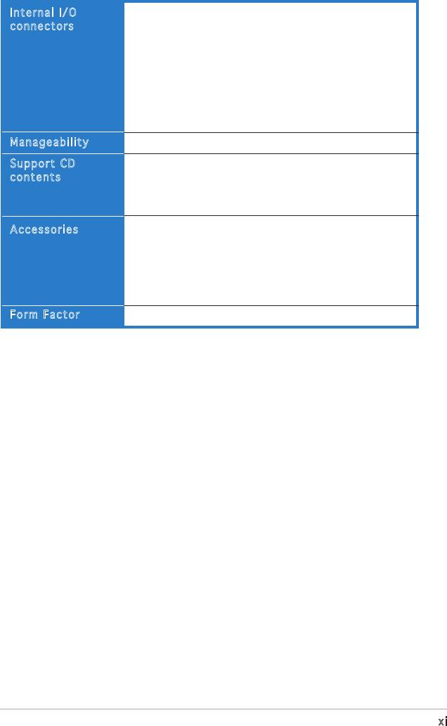
A8V-VM specications summary
Internal I/O
1 x 24-pin ATX power connector
connectors
1 x 4-pin ATX 12V power connector
2 x USB connectors for four additional USB 2.0 ports
1 x Front panel audio connector
1 x S/PDIF out connector
CPU/Chassis fan connectors
CD audio-in connector
Chassis intrusion connector
System panel connector
Manageability
Wfm2.0, DMI2.0, WOL by PME, WOR by PME, PXE, RPL
Support CD
Device drivers
contents
ASUS PC Probe II
ASUS LiveUpdate Utility
Anti-Virus software
User guide
Accessories
1 x UltraDMA cable
1 x FDD cable
I/0 shield
1 x SATA power cable
1 x SATA signal cable
Form Factor
ATX Form Factor: 9.6 in x 9.0 in (24.4 cm x 22.9 cm)
*Specications are subject to change without notice.
xi

This chapter describes the motherboard
features and the new technologies
it supports.
Product
1
introduction
®
1.1 Welcome!
®
Thank you for buying an ASUS
A8V-VM motherboard!
The motherboard delivers a host of new features and latest technologies,
making it another standout in the long line of ASUS quality motherboards!
Before you start installing the motherboard, and hardware devices on it,
check the items in your package with the list below.
1.2 Package contents
Check your motherboard package for the following items.
Motherboard ASUS A8V-VM motherboard
Cables 1xoppydiskdrivecable
1 x Ultral DMA 133/100/66 cable
1 x SATA power cable
1 x SATA signal cable
Accessories I/O shield
Application CDs ASUS motherboard support CD
Documentation User guide
If any of the above items is damaged or missing, contact your retailer.
1-2 Chapter 1: Product introduction
1.3 Special features
1.3.1 Product highlights
AMD Dual-Core Architecture
The motherboard supports AMD dual-core processors containing two
physical CPU cores with discrete L2 cache structure for each core to meet
demands for more powerful computing. See page 1-8 for details.See page 1-8 for details.
Latest processor and 64-bit
computing technology
The AMD Athlon™ 64FX, Athlon™ 64, Athlon™ 64x2, and AMD Sempron™ Sempron™
desktopprocessorsarebasedonAMD’s64-bitand32-bitarchitecture,
whichrepresentsthelandmarkintroductionoftheindustry’srstx86-64
technology. These processors provide a dramatic leap forward in
compatibility, performance, investment protection, and reduced total cost
of ownership and development. See page 1-8 for details.See page 1-8 for details.
Dual-channel DDR400 memory support
Employing the Double Date Rate (DDR) memory technology, the
motherboard supports up to 4GB of system meomory using DDR400/333
DIMMs. The ultra-fast 400MHz memory bus delivers the required bandwidth
for the latest 3D graphics, multimedia, and Internet applications See page
1-12 for details.
Integrated VIA DeltaChrome GPU
®
®
The VIA
K8M890 integrates the VIA
DeltaChrome graphics processing
unit (GPU) that supports a maximum VGA shared memory of 256MB,
®
Microsoft
DirectX 9.0, OpenGL 1.4, and PCI Express interface. See page
2-21 and 3-5.
6-Channel Audio and SoundMAX
High Definition Audio System
®
The onboard SoundMAX
ADI AD1986A 6-channel CODEC supports High
®
DenitionAudiostandard.SoundMAX
Digital Audio System can output 5.1
channel surround sound and features state-of-the-art DLS2 MIDI synthesizer
with Yamaha DLSbyXG sound set, 5.1 Virtual TheaterTM and supports all
major game audio technologies including Microsoft DirectXTM 8.0, Microsoft
DirectSound 3D, A3D, MacroFX, ZoomFX, MultiDrive 5.1, A3D and EAX. See
page 1-21 to 1-22 for details.
1-3ASUS A8V-VM
Serial ATA 3Gb/s technology
The motherboard supports the Serial ATA 3 Gb/s technology through
theSerialATAinterfaces.TheSerialATA3Gb/sspecicationprovides
twice the bandwidth of the current Serial ATA products with a host of
new features, including Native Command Queueing (NCQ), and Power
Management (PM) Implementation Algorithm. Serial ATA allows for thinner,
moreexiblecableswithlowerpincount,reducedvoltagerequirement.See
page 1-24 for details.
AMDCool‘n’Quiet!™Technology
ThemotherboardsupportstheAMDCool‘n’Quiet!™Technologythat
dynamically and automatically changes the CPU speed, voltage and amount
of power depending on the task the CPU performs.
1.3.2 Innovative ASUS features
CrashFree BIOS 2
This feature allows you to restore the original BIOS data from the support
CD in case when the BIOS codes and data are corrupted. This protection
eliminates the need to buy a replacement ROM chip. See page 2-6 for details.
ASUS MyLogo™
This new feature present in the motherboard allows you to personalize and
add style to your system with customizable boot logos. See page 2-31 for
details.
ASUS EZ Flash BIOS
With the ASUS EZ Flash, you can easily update the system BIOS even
before loading the operating system. No need to use a DOS-based utility or
bootfromaoppydisk.Seepage2-3fordetails.
1-4 Chapter 1: Product introduction
1.4 Before you proceed
Take note of the following precautions before you install components into
the system.
•
Unplug the power cord from the wall socket before touching any
component.
•
Use a grounded wrist strap or touch a safely grounded object or
a metal object, such as the power supply case, before handling
components to avoid damaging them due to static electricity.
•
Hold components by the edges to avoid touching the ICs on them.
•
Whenever you uninstall any component, place it on a grounded
antistatic pad or in the bag that came with the component.
•
Before you install or remove any component, ensure that the ATX
power supply is switched off or the power cord is detached from
the power supply. Failure to do so may cause severe damage to the
motherboard, peripherals, and/or components.
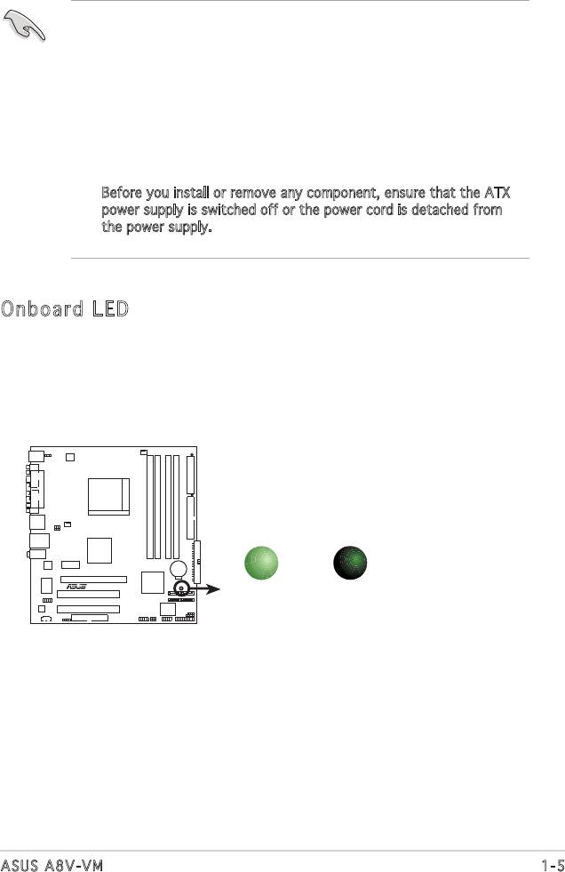
Onboard LED
The motherboard comes with a green standby power LED. This LED
lights up to indicate that the system is ON, in sleep mode or in soft-
off mode, and not powered OFF. Unplug the power cable from the
power outlet and make sure that the standby power LED is OFF before
installing any system component.
1-5ASUS A8V-VM
SB_PWR
A8V-VM
R
ON
OFF
Standby
Powered
Power
Off
A8V-VM Onboard LED
1.5 Motherboard overview
Beforeyouinstallthemotherboard,studythecongurationofyourchassis
toensurethatthemotherboardtsintoit.
Make sure to unplug the power cord before installing or removing the
motherboard. Failure to do so can cause you physical injury and damage
motherboard components.
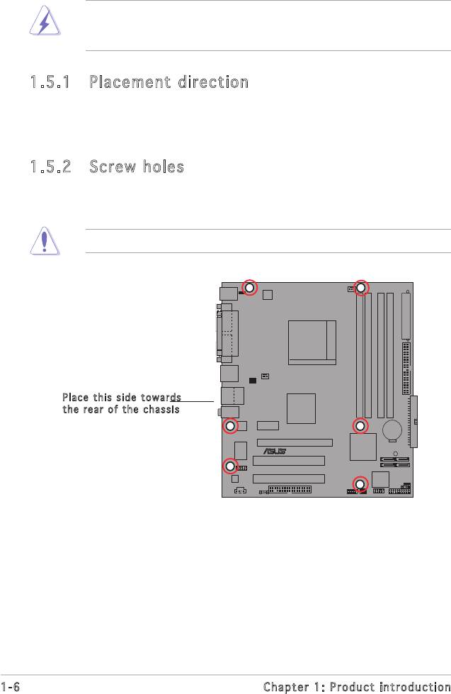
1.5.1 Placement direction
When installing the motherboard, make sure that you place it into the
chassis in the correct orientation. The edge with external ports goes to the
rear part of the chassis as indicated in the image below.
1.5.2 Screw holes
Place six (6) screws into the holes indicated by circles to secure the
motherboard to the chassis.
Do not overtighten the screws! Doing so can damage the motherboard.
Pl ace this side to war ds
th e r ear of the ch ass is
1-6 Chapter 1: Product introduction
A8V-VM
R
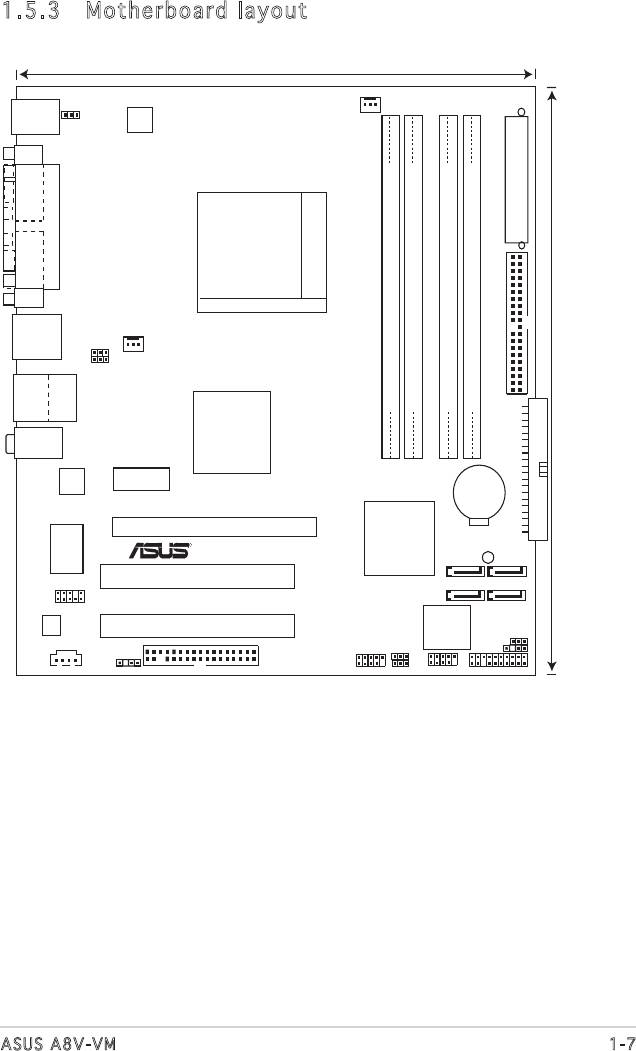
1.5.3 Motherboard layout
1-7ASUS A8V-VM
22.9cm (9.0in)
A8V
-
VM
CPU_FAN
KBPWR
R
PS/2KBMS
T: Mouse
B: Keyboard
ATX12V
COM1
EATXPWR
PARALLEL PORT
SOCKET 939
VGA
CHA_FAN
PRI_IDE
F_USB12
USBPW12
USBPW34
Bottom:
Top:
DDR DIMM_A1(64 bit,184-pin module)
DDR DIMM_A2(64 bit,184-pin module)
DDR DIMM_B1(64 bit,184-pin module)
DDR DIMM_B2(64 bit,184-pin module)
USB3
RJ-45
USB4
24.5cm (9.6in)
Top:Line In
VIA K8M890
Center:Line Out
Below:Mic In
Realtek
PCIEX1_1
SEC_IDE
CR2032 3V
Lithium Cell
A8V
-
VM
CMOS Powe
PCIEX16
VIA VT8251
SUPER
R
SB_PWR
I/O
SATA3
SATA2
PCI1
AAFP
SATA4
SATA1
Audio
4Mb Flash
PCI2
ROM
CLRTC
USBPW78
CHASSIS
USBPW56
CD
SPDIF_OUT
FLOPPY
USB56
USB78
PANEL
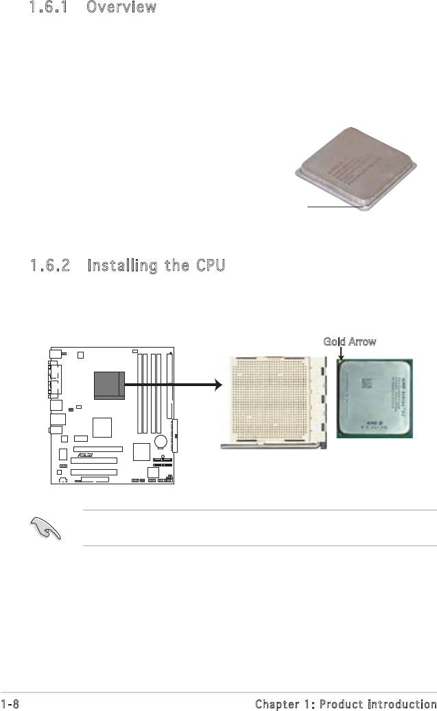
1.6.2 Installing the CPU
To install a CPU:
1. Locate the CPU socket on the motherboard.
Before installing the CPU, make sure that the socket box is facing
towards you and the load lever is on your left.
1-8 Chapter 1: Product introduction
Gold Arrow
A8V-VM
R
A8V-VM CPU Socket 939
1.6 Central Processing Unit (CPU)
1.6.1 Overview
The motherboard comes with a surface mount 939-pin Zero Insertion Force
(ZIF) socket designed for the AMD Athlon™ 64FX, AMD Athlon 64™, AMD
Athlon 64 X2 or AMD Sempron™ processor.
The 128-bit-wide data paths of these processors can run applications
faster than processors with only 32-bit or 64-bit wide data paths.
Take note of the marked corner
(with gold triangle) on the CPU. This
markshouldmatchaspeciccorner
on the socket to ensure correct
installation.
Gold triangle
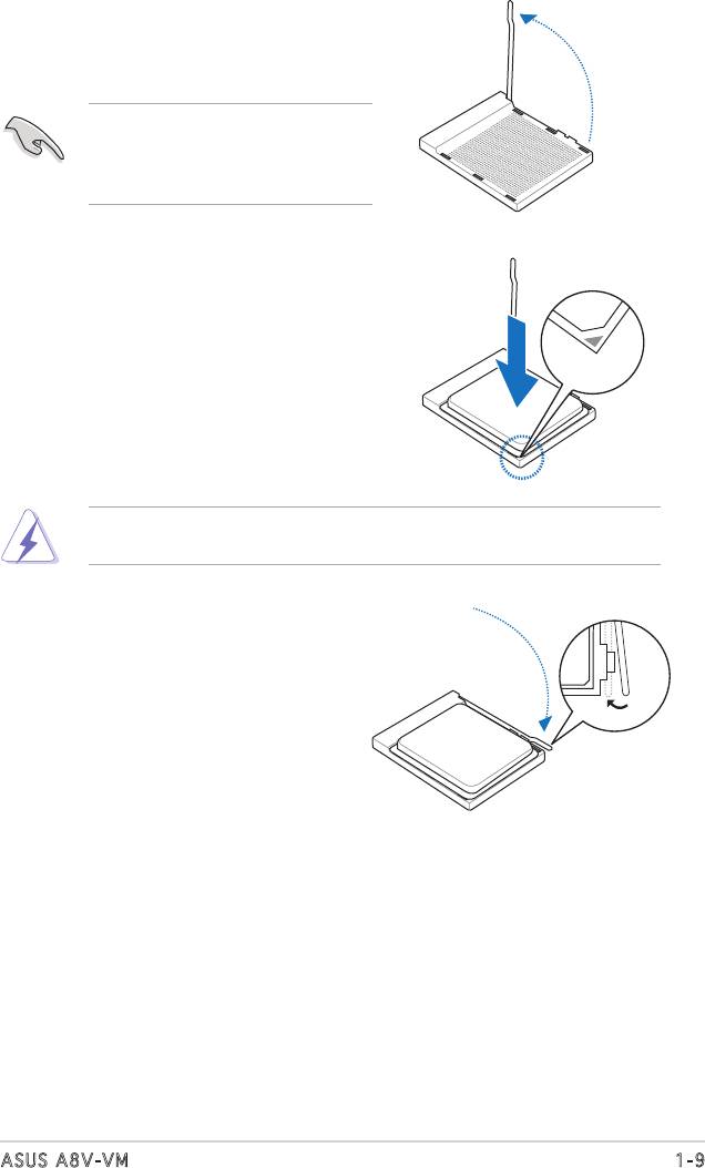
2. Unlock the socket by pressing the
lever sideways, then lift it up to a
90°-100° angle.
Make sure that the socket lever
is lifted up to 90°-100° angle,
otherwisetheCPUdoesnottin
completely.
3. Position the CPU above the socket
such that the CPU corner with the
gold triangle matches the socket
corner with a small triangle.
4. Carefully insert the CPU into the
socketuntilittsinplace.
TheCPUtsonlyinonecorrectorientation.DONOTforcetheCPUinto
the socket to prevent bending the pins and damaging the CPU!
5. When the CPU is in place, push down
the socket lever to secure the CPU.
The lever clicks on the side tab to
indicate that it is locked.
1-9ASUS A8V-VM
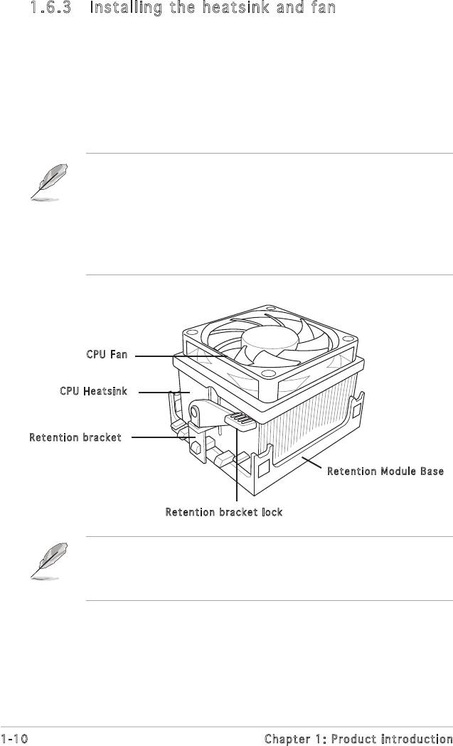
1.6.3 Installing the heatsink and fan
The AMD Athlon™ 64FX, Athlon™ 64X2, AMD Athlon 64™ or AMD
Sempron™ processor require a specially designed heatsink and fan assembly
to ensure optimum thermal condition and performance.
Follow these steps to install the CPU heatsink and fan.
1. Place the heatsink on top of the installed CPU, making sure that the
heatsinktsproperlyontheretentionmodulebase.
• The retention module base is already installed on the motherboard
upon purchase.
• You do not have to remove the retention module base when
installing the CPU or installing other motherboard components.
• If you purchased a separate CPU heatsink and fan assembly, make
sure that a Thermal Interface Material is properly applied to the CPU
heatsink or CPU before you install the heatsink and fan assembly.
CP U F an
CP U H eatsink
Re ten tion bracket
Re ten tion Module B ase
Re ten tion bracket loc k
Your boxed CPU heatsink and fan assembly should come with installation
instructions for the CPU, heatsink, and the retention mechanism. If the
instructions in this section do not match the CPU documentation, follow
the latter.
1-10 Chapter 1: Product introduction
1-11ASUS A8V-VM
Rotation
+12V
GND
CPU_FAN
A8V-VM
R
A8V-VM CPU Fan Connector
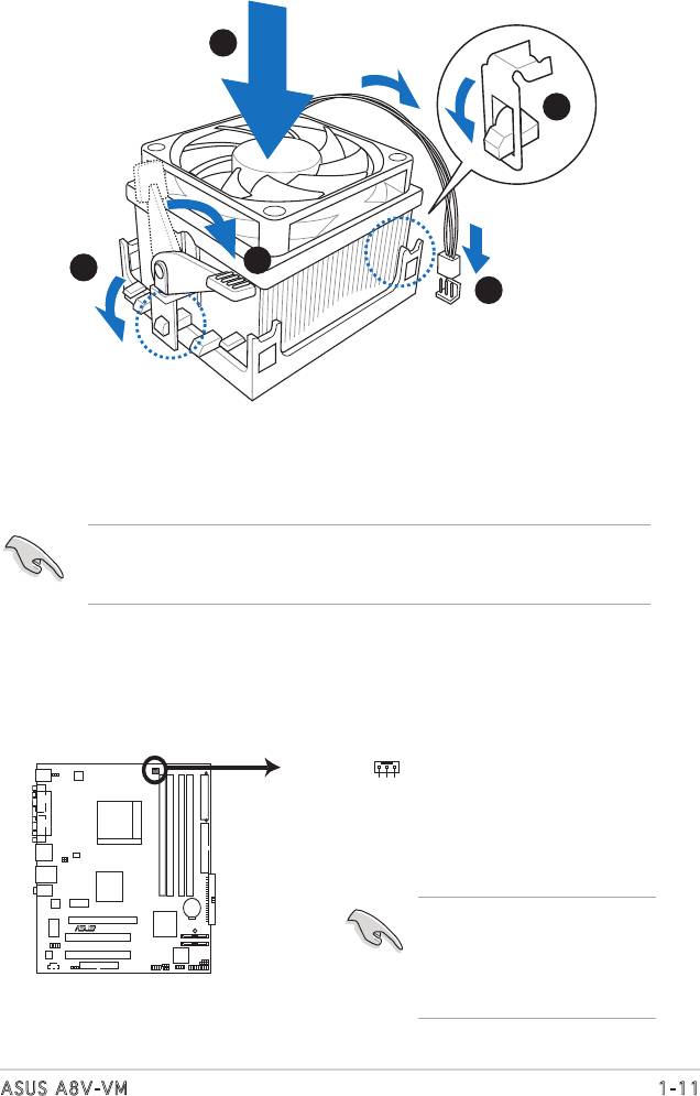
2. Attach one end of the retention bracket to the retention module base.
3. Align the other end of the retention bracket (near the retention
bracket lock) to the retention module base. A clicking sound denotes
that the retention bracket is in place.
Makesurethatthefanandheatsinkassemblyperfectlytsthe
retention mechanism module base, otherwise you cannot snap the
retention bracket in place.
4. Push down the retention bracket lock on the retention mechanism to
secure the heatsink and fan to the module base.
5. When the fan and heatsink assembly is in place, connect the CPU fan
cable to the connector on the motherboard labeled CPU_FAN.
1
2
4
3
5
Do not forget to connect the
CPU fan connector! Hardware
monitoring errors can
occur if you fail to plug this
connector.
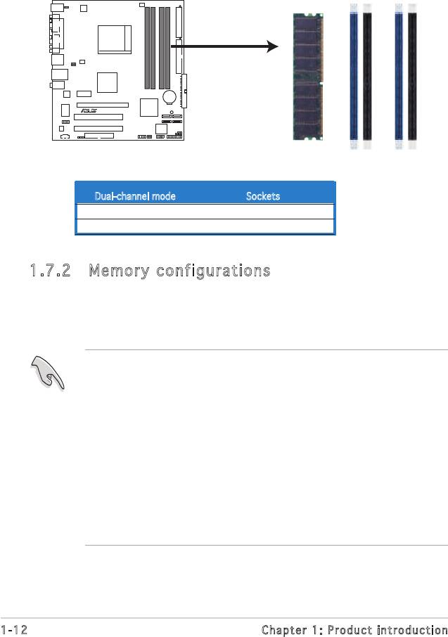
1.7 System memory
1.7.1 Overview
The motherboard comes with four 184-pin Double Data Rate (DDR) Dual
Inline Memory Module (DIMM) sockets.
Thefollowinggureillustratesthelocationofthesockets:
1.7.2 Memory configurations
You may install 128 MB, 256 MB, 512 MB, and 1 GB unbuffered ECC or
non-ECCDDRDIMMsintotheDIMMsocketsusingthememoryconguration
in this section.
• If you install four 1 GB memory modules, the system may detect less
than 3 GB of the total memory because of address space allocation
for other critical functions. This limitation applies to Windows XP
32-bit version operating system since it does not support Physical
Address Extension(PAE).
• When using one DDR DIMM module, insert it into slot DIMM_B1 only.
• When using two DDR DIMM modules, insert them into DIMM_A1 and
DIMM_B1 slots.
• Always install DIMMs with the same CAS latency. For optimum
compatibility, we recommend that you obtain memory modules from
thesamevendor.RefertotheDDR400QualiedVendorsListonthe
next page for details.
1-12 Chapter 1: Product introduction
DIMM_A1
DIMM_A2
DIMM_B1
DIMM_B2
A8V-VM
R
A8V-VM 184-pin DDR DIMM Sockets
Dual-channel mode Sockets
Pair 1 DIMM_A1 and DIMM_B1
Pair 2 DIMM_A2 and DIMM_B2
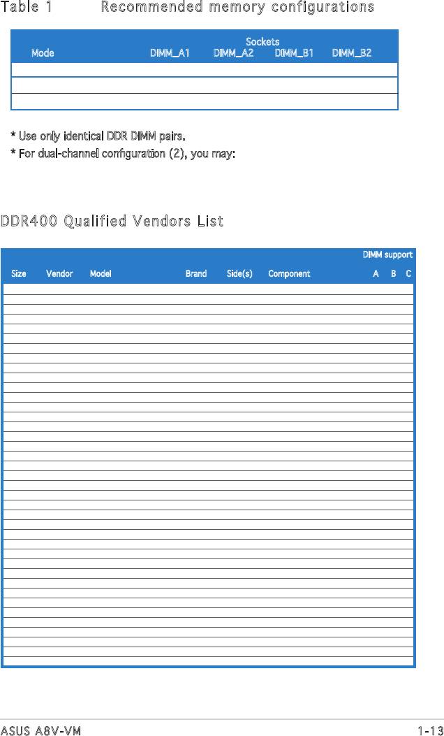
Table 1 Recommended memory configurations
Sockets
Mode DIMM_A1 DIMM_A2 DIMM_B1 DIMM_B2
Single-channel (1) — — Populated —
Dual-channel* (1) Populated — Populated —
(2) Populated Populated Populated Populated
* Use only identical DDR DIMM pairs.
*Fordual-channelconguration(2),youmay:
Install an identical DIMM pair in DIMM_A1 and DIMM_B1(blue sockets) and
the other identical DIMM pair in DIMM_A2 and DIMM_B2 (black sockets)
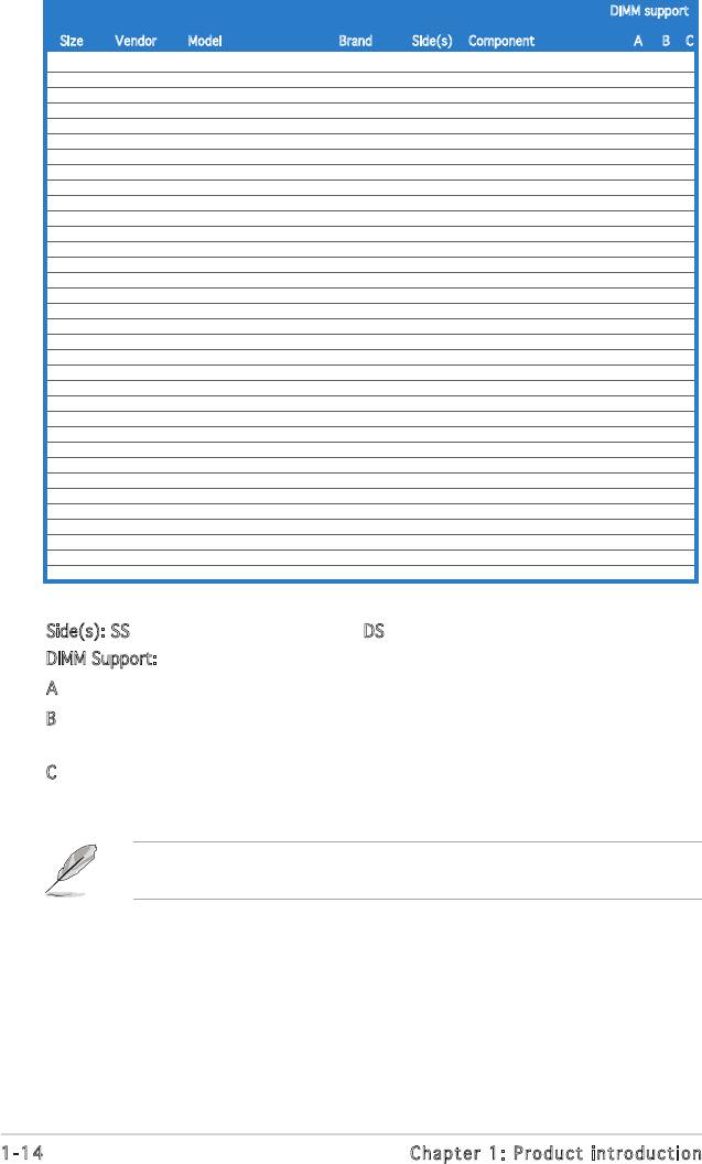
DDR400 Qualified Vendors List
DIMM support
Size Vendor Model Brand Side(s) Component A B C
256MB Kingston KVR333X64C25/256 Kingsto SS D3208DH1T-6 v v v
256MB Kingston KVR333X64C25/256 Hynix DS HY5DU56822BT-D43 v v v
512MB Kingston KVR333X64C25/512 Kingston DS D3208DH1T-6 v v v
512MB Kingston KVR400X64C3A/512 Hynix DS HY5DU56822BT-D43 v v v
512MB Kingston KVR400X64C3A/512 Kingston DS D3208DH1T-5 v v v
512MB Kingston KVR400X64C3A/512 Kingston SS HY5DU12822BT-D43 v v v
256MB Kingston KVR400X64C3A/256 Hynix SS HY5DU56822BT-D43 v v v
256MB Kingston KVR400X64C3A/256 Kingston SS D3208DL3T-5A v v v
256MB Kingston KVR400X64C3A/256 PSC SS A2S56D30BTP v v v
1G Kingston KVR400X64C3A/1G Inneon DS HYB25D512800BE-5B v v v
256MB Inneon HYS64D32300GU-5-C Inneon SS HYB25D256800CE-5C v v v
512MB Inneon HYS64D64320GU-5-C Inneon SS HYB25D512800BE-5B v v v
512MB Inneon HYS64D64320GU-5-C Inneon DS HYB25D256800CE-5C v v v
256MB Inneon HYS64D32300GU-5-C Inneon SS HYB25D256800CE-6C v v v
512MB Inneon HYS64D64320GU-6-C Inneon DS HYB25D256800CE-6C v v v
256MB HY HYMD232646D8J-D43 Hynix SS HY5DU56822BT-D43 v v v
512MB HY HYMD264646D8J-D43 Hynix DS HY5DU56822BT-D43 v v v
256MB HY HYMD232646B8J-J Hynix SS HY5DU56822BT-J v v v
512MB HY HYMD264646B8J-J Hynix DS HY5DU56822BT-J v v v
256MB Corsair VS256MB400 Value select SS VS32M8-5 2B0409 v v v
256MB Corsair XMS3202v3.1 Inneon SS HYB25D256807BT-5B v v v
512MB Corsair XMS3205v1.2 Winbond DS W942508CH-5 v v v
512MB Corsair VS512MB400 Value select DS VS32M8-5 2B0402 v v v
256MB Corsair VS256MB333 Samsung SS K4H5608380-TCB3 v v v
512MB Corsair XMS2702v3.1 Mosel DS V58C2256804SAT6 v v v
512MB Micron MT16VDDT6464AG-335GB Micron DS MT46V32M8TG-6TG v v v
256MB Micron MT8VDDT3264AG-335GB Micron SS MT46V32M8TG-6TG v v v
256MB Micron MT8VDDT3264AG-40BGB Micron SS MT46V32M8TG-5BG v v v
512MB Micron MT16VDDT6464AG-40BCB Micron DS MT46V32M8TG-5BC v v v
256MB Samsung M368L3223FTN-CCC Samsung SS K4H560838F-TCCC v v v
512MB Samsung M368L6423FTN-CCC Samsung DS K4H560838F-TCCC v v v
256MB Samsung M368L3223FTN-CB3 Samsung SS K4H560838F-TCB3 v v v
512MB Samsung M368L6423FTN-CB3 Samsung DS K4H560838F-TCB3 v v v
256MB Elpida U24256ADEPG6H20 Elpida SS DD2508AKTA-5C v v v
512MB Elpida U24512ADEPG6H20 Elpida DS DD2508AMTA v v v
512MB Apacer 77.90728.U1G Apacer DS AM3A568AJT-6B v v v
256MB Apacer 77.10636.46G Samsung SS K4H560838E-TCCC v v v
256MB Apacer 77.10636.56G Mosel SS V58C2256804SAT5B v v v
512MB Apacer 77.10736.11G Inneon DS HYB25D256800BT-5B v v v
1-13ASUS A8V-VM
DIMM support
Size Vendor Model Brand Side(s) Component A B C
256MB Transcend DDR400-256 Samsung SS K4H560838F-TCCC v v v
256MB Transcend DDR400-256 Mosel SS V58C2256804SAT5B v v v
512MB Transcend 102709-0001 PSC DS A2S56D3OATP v v v
512MB Transcend DDR400-512 Mosel DS V58C2256804SAT5B v v v
512MB Transcend DDR400-512 Samsung DS K4H560838F-TCCC v v v
256MB Transcend 111448-0214 PSC SS A2S56D30BTP v v v
512MB Transcend DDR333-512 Hynix DS HY5DU56822CT-J v v v
256MB Kingmax MPMB62D-38LT3R Mosel SS V58C2256804SAT6 v v v
512MB Kingmax MPMC22D-38HT3R Hynix DS HY5DU56822BT-J v v v
256MB Kingmax MPXB62D-38KT3R Kingmax SS KDL388P4LA-50 v v v
512MB Kingmax MPXC22D-38KT3R Kingmax DS KDL388P4EA-50 v v v
256MB Vdata MDYVD6F4G2880B1E0H Vdata SS VDD9616A8A-5C v v v
256MB Pmi 3208GATA07-04A7 Pmi SS PM4D328D50406EU v v v
512MB Mosel V826632K24SATG-D3 Mosel SS V58C2256804SAT5 v v v
512MB Mosel V826664K24SATG-D3 Mosel DS V58C2256804SAT5 v v v
256MB Nanya NT256D64S88B1G-5T Nanya SS NT5DS32M8BT-5T v v v
512MB Nanya NT512D64S8HB1G-5T Nanya DS NT5DS32M8BT-5T v v v
512MB Nanya NT512D64S88C0GY-5T Nanya SS NT5DS64M8CS-5T v v v
1G Nanya NT1GD64S8HC0GY-5T Nanya DS NT5DS64M8CS-5T v v v
256MB Smart U24256ADSRG6H20 Smart SS D32M8XS50H3X4AMV v v v
256MB Smart U24256ADSRG6H20 Smart SS D32M8XS60HBX4AMV v v v
512MB Smart U24512ADSRG6H20 Smart DS D32M8XS50H3X4AMV v v v
512MB Smart U24512ADSRG6H20 Smart DS D32M8XS60HBX4AMV v v v
256MB Twinmos DDR333-256 Twinmos SS TMD7608F8E60B v v v
256MB Twinmos M2G9108A-TT Twinmos SS TMD7608F8E501 v v v
256MB Promos V826632K24SCTG-D0 Promos SS V58C2256804SCT5B v v v
512MB Promos V826664K24SCTG-D0 Promos DS V58C2256804SCT5B v v v
512MB BiaoXing BXXC22D-38KT3B BiaoXing DS VM256D328BT-5 v v v
256MB Winbond U24256ADWBG6H20 Winbond SS W942508CH-5 v v v
256MB Winbond U24256AAWBG6H20 Winbond SS W942508CH-6 v v v
512MB Winbond DDR333-512 Winbond DS W942508BH-6 v v v
512MB Winbond U24512ADWBG6H20 Winbond DS W942508CH-5 v v v
512MB Patriot PDC1G3200+XBLK Patriot DS v v v
512MB MDT MDT 512MB MDT DS MDT25B25680-50530 v v v
Side(s): SS - Single-Sided DS - Double-Sided
DIMM Support:
A- supportsonemoduleasasingle-channelmemoryconguration.
B - supports one pair of modules inserted into either the blue slots or the
blackslotsasonepairofdual-channelmemoryconguration.
C - support for 4 modules inserted into the blue and black slots as two
pairsofdual-channelmemoryconguration.
VisittheASUSwebsite(www.asus.com)forthelatestDDR400Qualied
Vendors List.
1-14 Chapter 1: Product introduction
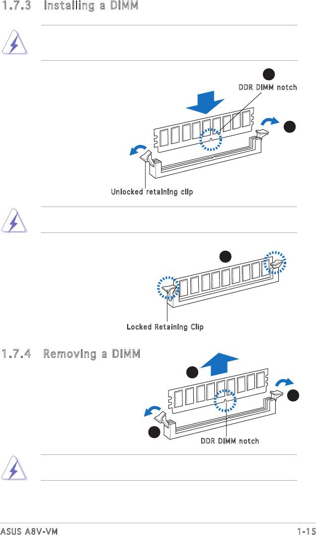
1.7.3 Installing a DIMM
Make sure to unplug the power supply before adding or removing DIMMs
or other system components. Failure to do so may cause severe damage
to both the motherboard and the components.
2
1. Unlock a DIMM socket by
DD R D IMM notch
pressing the retaining clips
outward.
2. Align a DIMM on the socket
1
such that the notch on the
DIMM matches the break on the
socket.
1
Un loc ked retaining cl ip
ADDRDIMMiskeyedwithanotchsothatittsinonlyonedirection.
DO NOT force a DIMM into a socket to avoid damaging the DIMM.
3. Firmly insert the DIMM into the
3
socket until the retaining clips
snap back in place and the DIMM
is properly seated.
Lo cke d Retaining C lip
1.7.4 Removing a DIMM
Follow these steps to remove a DIMM.
2
1
1. Simultaneously press the
retaining clips outward to
unlock the DIMM.
1
DD R D IMM notch
SupporttheDIMMlightlywithyourngerswhenpressingtheretaining
clips.TheDIMMmightgetdamagedwhenitipsoutwithextraforce.
2. Remove the DIMM from the socket.
1-15ASUS A8V-VM
1.8 Expansion slots
In the future, you may need to install expansion cards. The following
sub-sections describe the slots and the expansion cards that they support.
Make sure to unplug the power cord before adding or removing
expansion cards. Failure to do so may cause you physical injury and
damage motherboard components.
1.8.1 Installing an expansion card
To install an expansion card:
1. Before installing the expansion card, read the documentation that
came with it and make the necessary hardware settings for the card.
2. Remove the system unit cover (if your motherboard is already
installed in a chassis).
3. Remove the bracket opposite the slot that you intend to use. Keep
the screw for later use.
4. Alignthecardconnectorwiththeslotandpressrmlyuntilthecardis
completely seated on the slot.
5. Secure the card to the chassis with the screw you removed earlier.
6. Replace the system cover.
1.8.2 Configuring an expansion card
Afterinstallingtheexpansioncard,congureitbyadjustingthesoftware
settings.
1. Turn on the system and change the necessary BIOS settings, if any.
See Chapter 2 for information on BIOS setup.
2. Assign an IRQ to the card. Refer to the tables on the next page.
3. Install the software drivers for the expansion card.
1-16 Chapter 1: Product introduction
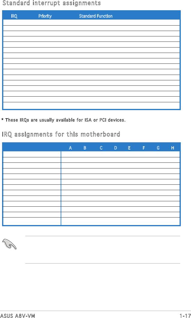
Standard interrupt assignments
IRQ Priority Standard Function
0 1 System Timer
1 2 Keyboard Controller
2 - Programmable interrupt
3 11 Communications Port (COM2)*
4 12 -
5 13 IRQ holder for PCI steering*
6 14 Floppy Disk Controller
7 15 Printer Port (LPT1)*
8 3 System CMOS/Real Time Clock
9 4 IRQ holder for PCI steering*
10 5 MIDI port*
11 6 IRQ holder for PCI steering*
12 7 PS/2 Compatible Mouse Port*
13 8 Numeric Data Processor
14 9 Primary IDE Channel
15 10 Secondary IDE Channel
* The se IRQs are u sua lly available fo r ISA or PCI dev ices.
IRQ assignments for this motherboard
A B C D E F G H
PCI slot 1 shared — — — — — — —
PCI slot 2 — shared — — — — — —
PCI Express x16 slot — — — — — — — shared— — — — — — — shared — — — — — — shared
PCI Express x1 slot 1 — — — — — — — shared— — — — — — — shared — — — — — — shared
Onboard USB controller 0 shared — — — — — — —
Onboard USB controller 1 — — shared — — — — —
Onboard USB controller 2 — shared — — — — —
Onboard USB controller 3 — — — shared — — — —
Onboard EHCI controller — — shared — — — — —
Onboard SATA Controller — shared — — — — — —
Onboard Audio Controller — shared — — — — — —
Onboard LAN shared — — — — — — —
Integrated graphics shared — — — — — — —
When using PCI cards on shared slots, ensure that the drivers support
“Share IRQ” or that the cards do not need IRQ assignments; otherwise,
conictswillarisebetweenthetwoPCIgroups,makingthesystem
unstable and the card inoperable.
1-17ASUS A8V-VM
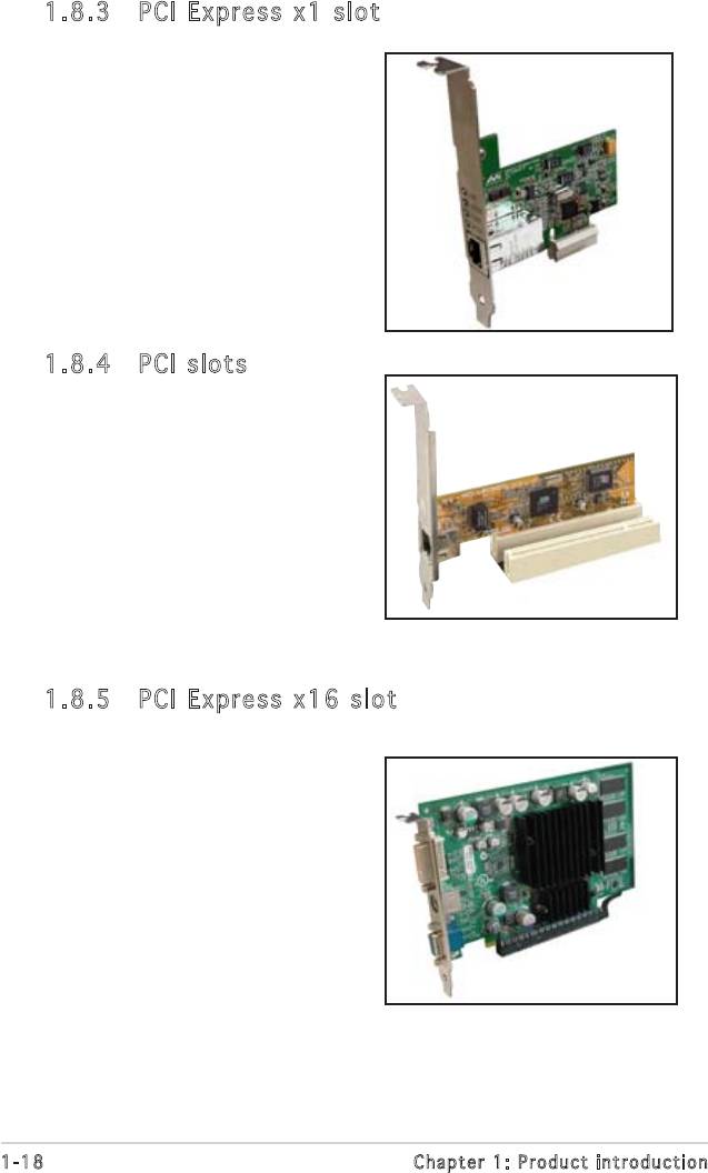
1.8.3 PCI Express x1 slot
This motherboard supports PCI
Express x1 network cards, SCSI cards
and other cards that comply with the
PCIExpressspecications.Thegure
shows a network card installed on the
PCI Express x1 slot.
1.8.4 PCI slots
The PCI slots support cards such as
a LAN card, SCSI card, USB card, and
other cards that comply with PCI
specications.Thegureshowsa
LAN card installed on a PCI slot.
1.8.5 PCI Express x16 slot
This motherboard supports PCI Express
x16 graphic cards that comply with
thePCIExpressspecications.The
gureshowsagraphicscardinstalled
on the PCI Express x16 slot.
1-18 Chapter 1: Product introduction
1.9 Jumpers
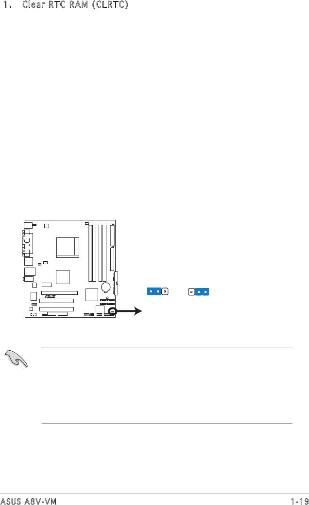
1. Clear RTC RAM (CLRTC)
This jumper allows you to clear the Real Time Clock (RTC) RAM in
CMOS. You can clear the CMOS memory of date, time, and system
setup parameters by erasing the CMOS RTC RAM data. The onboard
button cell battery powers the RAM data in the CMOS, which includes
the system setup information such as system passwords.
To erase the RTC RAM:
1. Turn OFF the computer and unplug the power cord.
2. Remove the battery.
3. Move the jumper cap from pins 1-2 (default) to pins 2-3. Keep
the cap on pins 2-3 for about 5-10 seconds, then move the cap
back to pins 1-2.
4. Re-install the battery.
5. Plug the power cord and turn ON the computer.
6. Hold down the <Del> key during the boot process and enter BIOS
setup to re-enter data.
• Except when clearing the RTC RAM, never remove the cap on CLRTC
jumper default position. Removing the cap will cause system boot
failure.
• For system failure due to overclocking, you do not need to clear the
RTC, and just use the C.P.R. (CPU Parameter Recall) feature. Shut
down and reboot the system to restore the default BIOS parameter
settings. when the system hangs due to overclocking.
1-19ASUS A8V-VM
CLRTC
2 31 2
A8V-VM
R
Normal Clear CMOS
(Default)
A8V-VM Clear RTC RAM
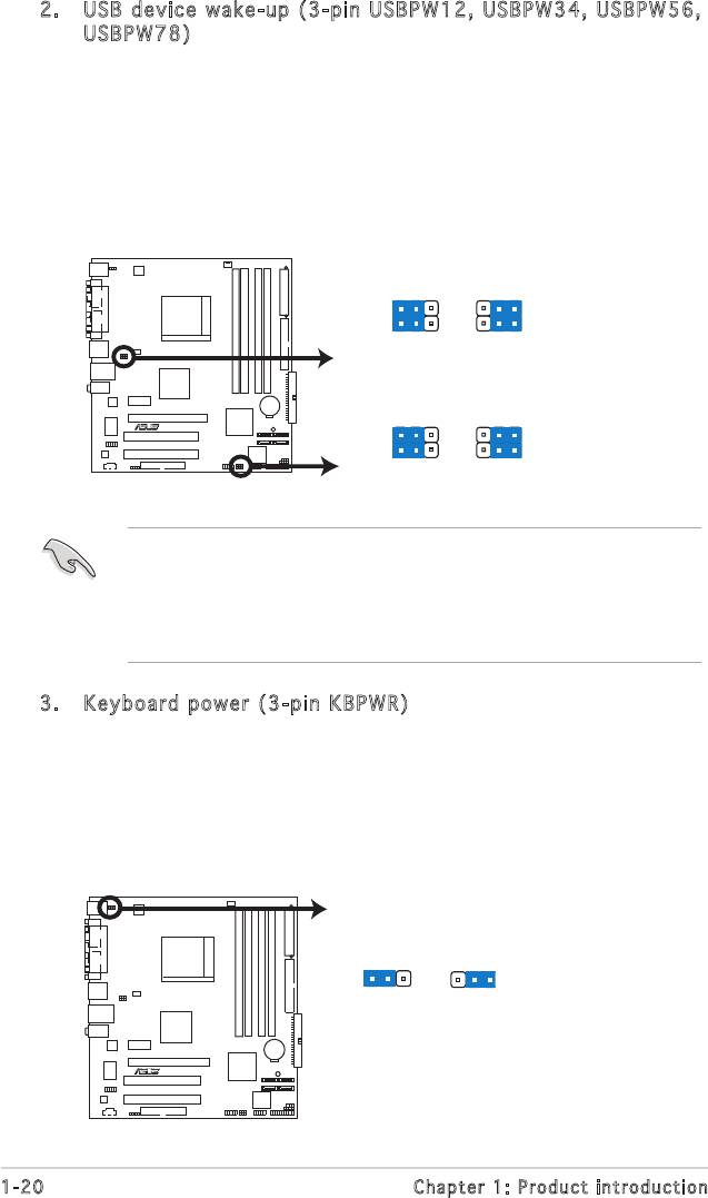
2. USB device wake-up (3-pin USBPW1 2, USBPW34, USBPW56,
USBPW78)
Set these jumpers to +5V to wake up the computer from S1 sleep
mode (CPU stopped, DRAM refreshed, system running in low power
mode) using the connected USB devices. Set to +5VSB to wake up
from S3 and S4 sleep modes (no power to CPU, DRAM in slow refresh,
power supply in reduced power mode).
The USBPW12 and USBPW34 jumpers are for the rear USB ports. The
USBPW56 and USBPW78 jumpers are for the internal USB connectors.
• The USB device wake-up feature requires a power supply that can
provide 500mA on the +5VSB lead for each USB port; otherwise,
the system would not power up.
• The total current consumed must NOT exceed the power supply
capability (+5VSB) whether under normal condition or in sleep mode.
1-20 Chapter 1: Product introduction
USBPW12
USBPW34
21
2
3
+5V
+5VSB
(Default)
USBPW78
USBPW56
A8V-VM
R
21
2
3
+5V
+5VSB
(Default)
A8V-VM USB Device Wake Up
3. Keyboard power (3-pin KBPWR)
This jumper allows you to enable or disable the keyboard wake-up
feature. Set this jumper to pins 2-3 (+5VSB) if you wish to wake up
the computer when you press a key on the keyboard (the default is
the Space Bar). This feature requires an ATX power supply that can
supply at least 1A on the +5VSB lead, and a corresponding setting in
the BIOS.
KBPWR
2 31 2
+5V +5VSB
(Default)
A8V-VM
R
A8V-VM Keyboard Power Setting
1.10 Connectors
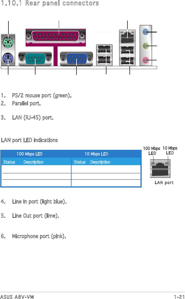
1.10.1 Rear panel connectors
1. PS/2 mouse port (green). This port is for a PS/2 mouse.
2. Parallel port. This 25-pin port connects a parallel printer, a scanner, or
other devices.
3. LAN (RJ-45) port. This port allows Gigabit connection with a speed
of 100 Mbps to a Local Area Network (LAN) through a network hub.
Refer to the table below for the LAN port LED indications.
LAN port LED indications
100 Mbps
10 Mbps
100 Mbps LED 10 Mbps LED
L ED
LE D
Status Description Status Description
Orange 100 Mbps connection OFF No link
OFF No link GREEN 10 Mbps connection
BLINKING Transmitting and receiving BLINKING Transmitting and receiving
LA N p ort
4. Line In port (light blue). This port connects a tape, CD, DVD player, or
other audio sources.
5. Line Out port (lime). This port connects a headphone or a speaker.
In4-channeland6-channelconguration,thefunctionofthisport
becomes Front Speaker Out.
6. Microphone port (pink). This port connects a microphone.
1-21ASUS A8V-VM
1
2 3
4
5
6
11 7
10
9
8
1.10.2 Internal connectors
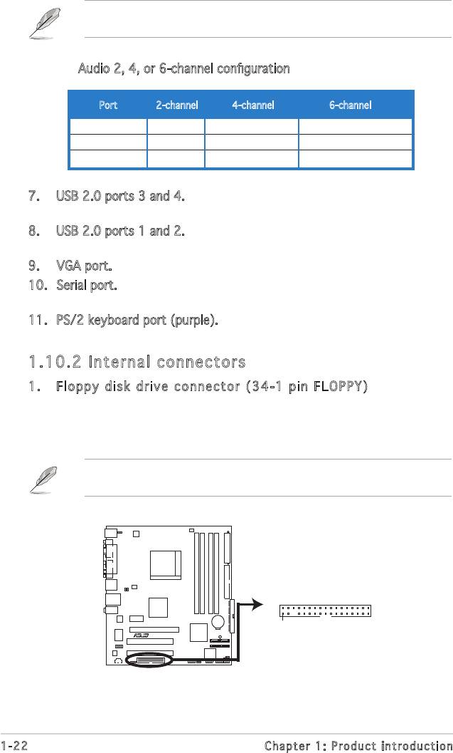
1. Floppy disk drive connector (34-1 pin FLOPPY)
Thisconnectorisfortheprovidedoppydiskdrive(FDD)signalcable.
Insert one end of the cable to this connector, then connect the other
endtothesignalconnectoratthebackoftheoppydiskdrive.
Pin 5 on the connector is removed to prevent incorrect cable connection
when using a FDD cable with a covered Pin 5.
1-22 Chapter 1: Product introduction
FLOPPY
A8V-VM
PIN 1
R
NOTE: Orient the red markings on
the floppy ribbon cable to PIN 1.
A8V-VM Floppy Disk Drive Connector
Refertotheaudiocongurationtablebelowforthefunctionoftheaudio
portsin2,4,or6-channelconguration.
Audio2,4,or6-channelconguration
Port 2-channel 4-channel 6-channel
Light Blue Line In Back Surround Back Surround
Lime Line Out Front Speaker Out Front Speaker Out
Pink Mic In Mic In Center/Base
7. USB 2.0 ports 3 and 4. These two 4-pin Universal Serial Bus (USB)
ports are available for connecting USB 2.0 devices.
8. USB 2.0 ports 1 and 2. These two 4-pin Universal Serial Bus (USB)
ports are available for connecting USB 2.0 devices.
9. VGA port. This 15-pin VGA port connects to a VGA monitor.
10. Serial port. This port connects a mouse, modem, or other devices that
conformwithserialspecication.
11. PS/2 keyboard port (purple). This port is for a PS/2 keyboard.
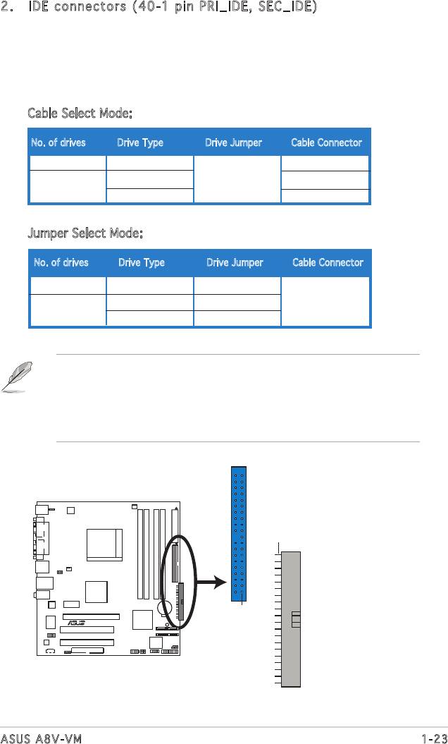
• Pin 20 on the IDE connector is removed to match the covered hole
on the Ultra DMA cable connector. This prevents incorrect insertion
when you connect the IDE cable.
• Use the 80-conductor IDE cable for Ultra DMA 133/100/66/33
IDE devices.
1-23ASUS A8V-VM
NOTE: Orient the red markings on
the floppy ribbon cable to PIN 1.
PRI_IDE
PIN 1
A8V-VM
SEC_IDE
PIN 1
R
A8V-VM IDE Connectors
2. IDE connectors (40-1 pin PRI_IDE, SEC_IDE)
These connectors are for Ultra DMA 133/100/66 signal cables.
There are three interfaces on each Ultra DMA 133/100/66 signal
cables: blue, black, and gray. Connect the blue interface into the
motherboad’sIDEconnector,thenselectthefollowingmodesto
congureyourharddiskdrive(s).
Cable Select Mode: to select the operating mode by cable connectors.
No. of drives Drive Type Drive Jumper Cable Connector
1 With OS Black
2 With OS Cable select Black
Without OS Gray
Jumper Select Mode: to select the operating mode by hard-disk drive jumper.
No. of drives Drive Type Drive Jumper Cable Connector
1 With OS Master
2 With OS Master Black or gray
Without OS Slave
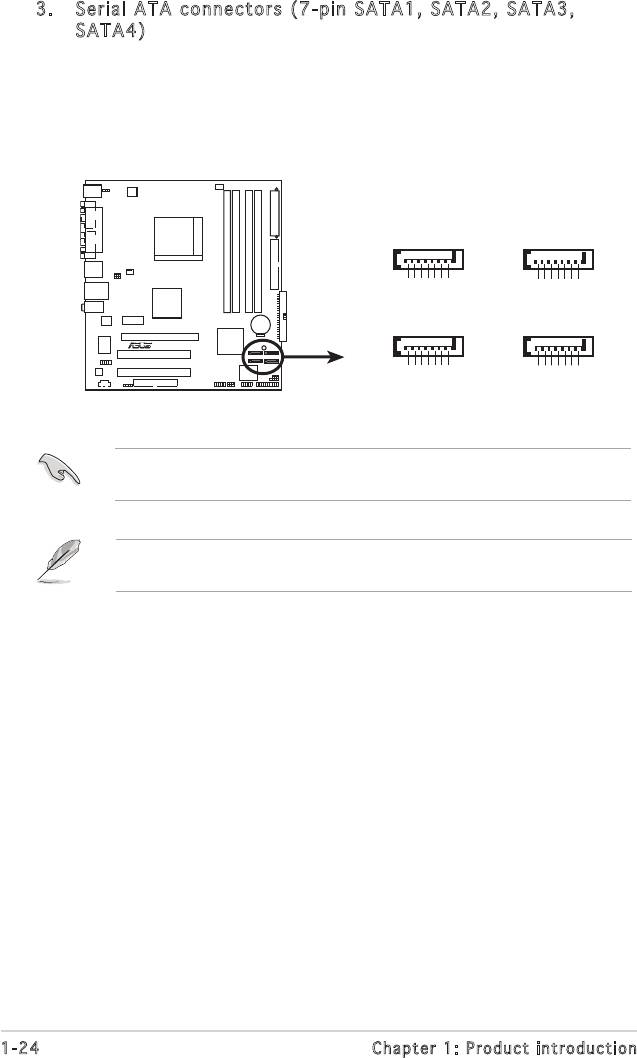
3. Serial ATA connectors ( 7-pin SATA1, SATA2, SATA3,
SATA4)
These connectors are for the Serial ATA signal cables for Serial ATA
hard disk drives. The current Serial ATA I interface allows up to 150
MB/s data transfer rate while Serial ATA II allows up to 300 MB/s data
transfer rate, faster than the standard parallel ATA with 133 MB/s
(Ultra DMA/133)
®
®
Install the Windows
2000 Service Pack 4 or the Windows
XP Service
Pack1 before using Serial ATA.
FordetailedinstructionsonhowtocongureRAID0,RAID1,RAID0+1,
RAID 5 and JBOD, refer to the RAID manual in the support CD.
1-24 Chapter 1: Product introduction
SATA3
SATA2
GND
GND
GND
GND
GND
GND
RSATA_TXP3
RSATA_TXN3
RSATA_RXN3
RSATA_RXP3
RSATA_TXP2
RSATA_TXN2
RSATA_RXN2
RSATA_RXP2
A8V-VM
R
SATA4
SATA1
GND
GND
GND
GND
GND
GND
RSATA_TXP4
RSATA_TXN4
RSATA_RXP4
RSATA_RXN4
RSATA_TXP1
RSATA_TXN1
RSATA_RXN1
RSATA_RXP1
A8V-VM CPU SATA Connectors
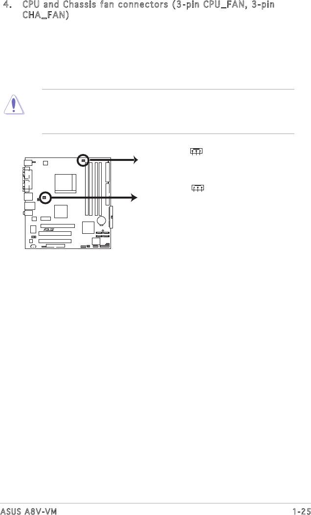
4. CPU and Chassis fan connectors (3-pin CPU_FAN, 3-pin
CHA_FAN)
The fan connectors support cooling fans of 350 mA~740 mA (8.88
W max.) or a total of 1 A~2.22 A (26.64 W max.) at +12V. Connect
the fan cables to the fan connectors on the motherboard, making
sure that the black wire of each cable matches the ground pin of the
connector.
Do not forget to connect the fan cables to the fan connectors.
Insufcientairowinsidethesystemmaydamagethemotherboard
components. These are not jumpers! Do not place jumper caps on the
fan connectors!
1-25ASUS A8V-VM
Rotation
+12V
GND
CPU_FAN
Rotation
+12V
GND
CHA_FAN
A8V-VM
R
A8V-VM Fan Connectors
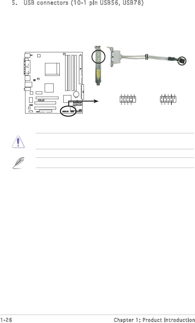
5. USB connectors (10-1 pin USB56, USB 78)
These connectors are for USB 2.0 ports. Connect the USB module
cable to any of these connectors, then install the module to a slot
opening at the back of the system chassis. These USB connectors
complywithUSB2.0specicationthatsupportsupto480Mbps
connection speed.
Never connect a 1394 cable to the USB connectors. Doing so will
damage the motherboard!
1-26 Chapter 1: Product introduction
USB+5V
USB_P6-
USB_P6+
GND
NC
USB+5V
USB_P8-
USB_P8+
GND
NC
A8V-VM
R
USB56
USB78
1
1
GND
GND
USB+5V
USB_P5-
USB+5V
A8V-VM USB 2.0 Connectors
USB_P5+
USB_P7-
USB_P7+
The USB2.0 module is purchased separately .
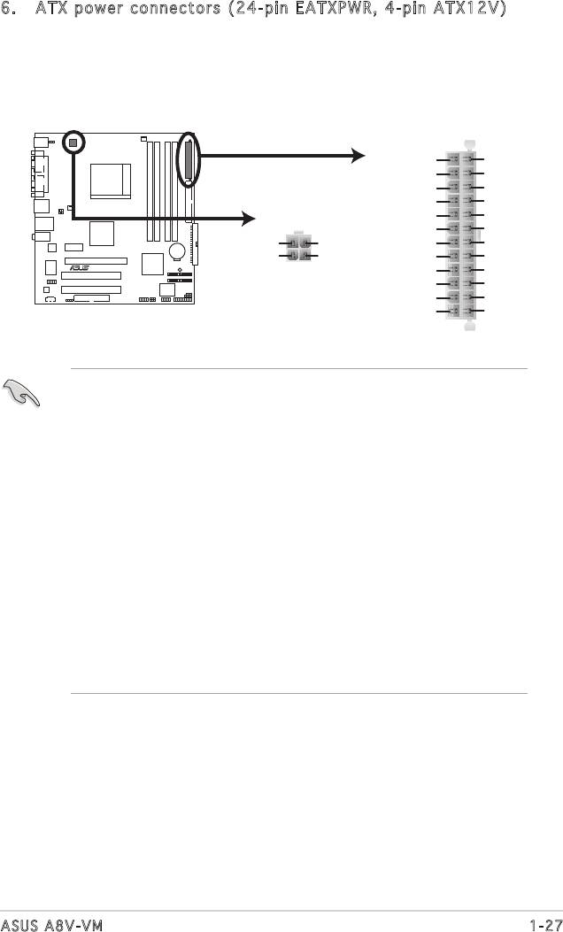
6. ATX power connectors (24-pin EATXPWR, 4-pin ATX12V)
These connectors are for ATX power supply plugs. The plugs from
thepowersupplyaredesignedtottheseconnectorsinonlyone
orientation.Findtheproperorientationandpushdownrmlyuntilthe
connectorscompletelyt.
1-27ASUS A8V-VM
EATXPWR
+3 Volts
Ground
+12 Volts
+5 Volts
+12 Volts
+5 Volts
+5V Standby
+5 Volts
ATX12V
Power OK
-5 Volts
Ground
Ground
+12V DC
+12V DC
+5 Volts
Ground
A8V-VM
GND
GND
Ground
Ground
R
+5 Volts
PSON#
Ground
Ground
+3 Volts
-12 Volts
+3 Volts
+3 Volts
A8V-VM ATX Power Connectors
•
WerecommendthatyouuseanATX12VSpecication
2.0-compliant power supply unit (PSU) with a minimum of 300 W
power rating. This PSU type has 24-pin and 4-pin power plugs.
•
If you intend to use a PSU with 20-pin and 4-pin power plugs, make
sure that the 20-pin power plug can provide at least 15 A on +12
V and that the PSU has a minimum power rating of 300 W. The
system may become unstable or may not boot up if the power is
inadequate.
•
Do not forget to connect the 4-pin ATX +12 V power plug;
otherwise, the system will not boot up.
• We recommend that you use a PSU with higher power output when
conguringasystemwithmorepower-consumingdevices.The
system may become unstable or may not boot up if the power is
inadequate.
•
You must install a PSU with a higher power rating if you intend to
install additional devices.
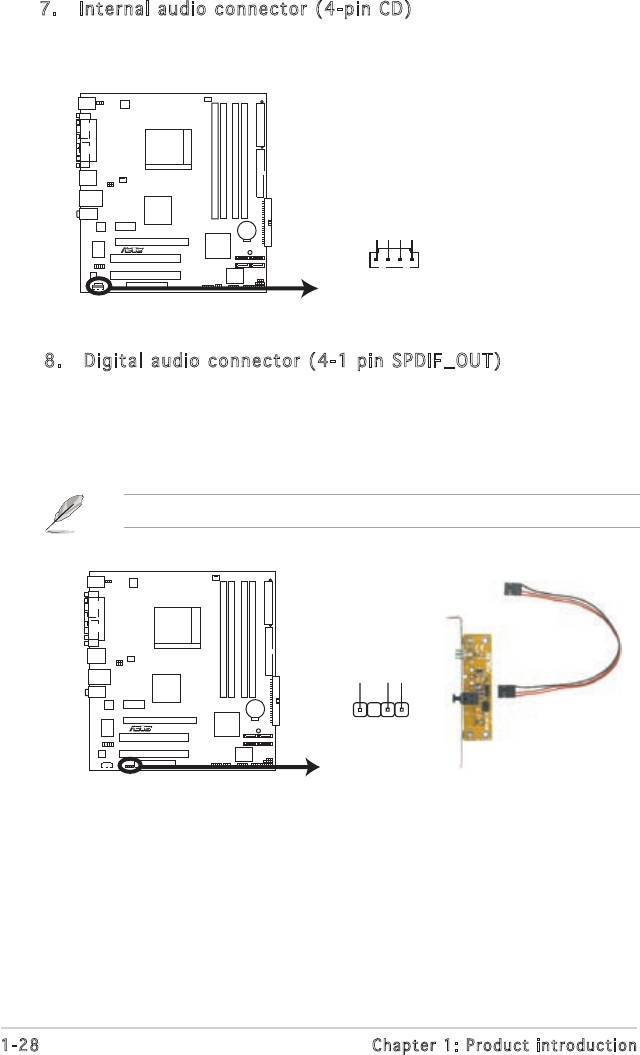
7. Internal audio connector (4-pin CD)
This connector is for the 4-pin audio cable that connects to the audio
connector at the back of the optical drive.
1-28 Chapter 1: Product introduction
CD
(black)
A8V-VM
Right Audio Channel
Ground
Ground
Left Audio Channel
R
A8V-VM Internal Audio Connector
8. Digital audio connector (4-1 pin SPDIF_OUT)
This connector is for an additional Sony/Philips Digital Interface
(S/PDIF) port(s). Connect the S/PDIF module cable to this connector,
then install the module to a slot opening at the back of the system
chassis.
The S/PDIF module is purchased separately.
+5V
SPDIFOUT
GND
A8V-VM
R
SPDIF_OUT
A8V-VM Digital Audio Connector
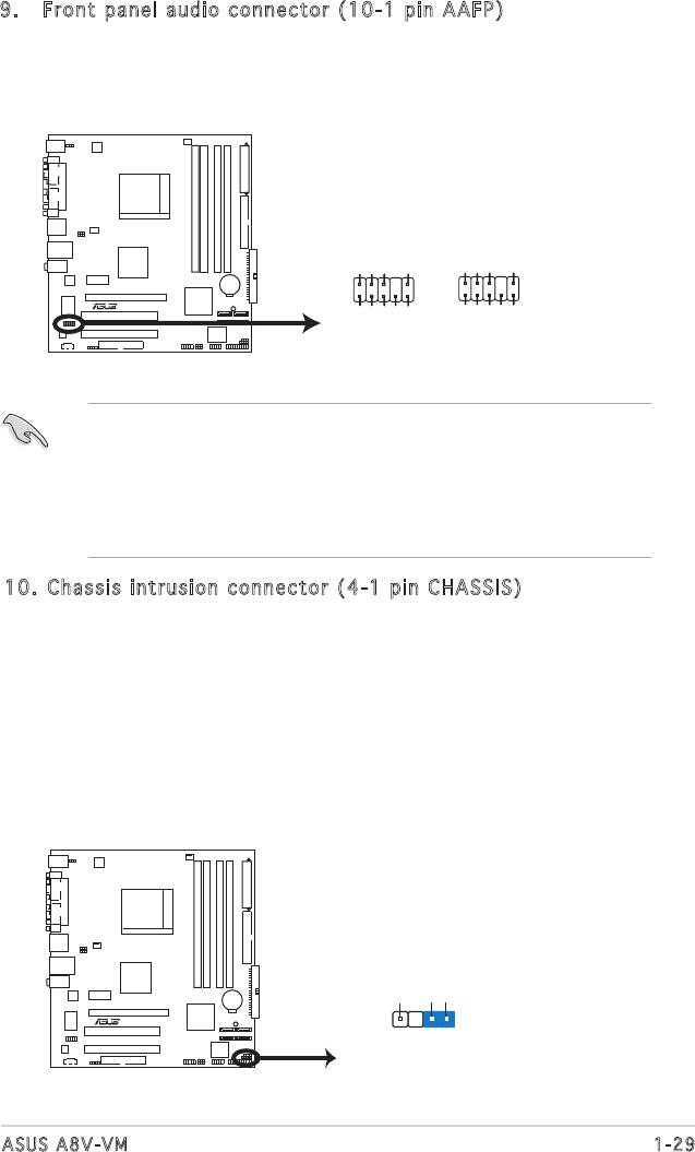
9. Front panel audio connector (10-1 pin AAFP)
This connector is for a chassis-mounted front panel audio I/O module
thatsupportseitherHighDenitionAudioorAC`97audiostandard.
Connect one end of the front panel audio I/O module cable to this
connector.
• Werecommendthatyouconnectahigh-denitionfrontpanel
audio module to this connector to avail of the motherboard high-
denitionaudiocapability.
• Ifyouwanttoconnectahigh-denitionfrontpanelaudiomoduleto
this connector, make sure the Audio Controller item in the BIOS is
set to [Enabled]. See page 2-22 for details.
1-29ASUS A8V-VM
AAFP
Azalia compliant
Legacy AC 97
definition
compliant definition
GND
PRESENCE#
SENSE1_RETUR
SENSE2_RETUR
AGND
+5VA
Back line out R
Back line out L
A8V-VM
R
NC
AGND
+5VA
PORT1 L
PORT1 R
PORT2 R
PORT2 L
Line out_R
Line out_L
SENSE_SEND
A8V-VM Analog Front Panel Connector
10. Chassis intrusion connector (4-1 pin CHASSIS)
This connector is for a chassis-mounted intrusion detection sensor
or switch. Connect one end of the chassis intrusion sensor or switch
cable to this connector. The chassis intrusion sensor or switch sends
a high-level signal to this connector when a chassis component
is removed or replaced. The signal is then generated as a chassis
intrusion event.
By default, the pins labeled “Chassis Signal” and “Ground” are shorted
with a jumper cap. Remove the jumper caps only when you intend to
use the chassis intrusion detection feature.
+5VSB_MB
Chassis Signal
GND
A8V
-
VM
R
CHASSIS
(Default)
A8V-VM Chassis Intrusion Connector
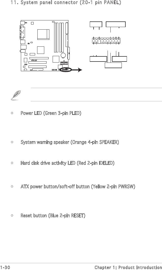
11. System panel connector (20-1 pin PANEL)
This connector supports several chassis-mounted functions.
The sytem panel connector is color-coded for easy connection. Refer to
the connector description below for details.
• Power LED (Green 3-pin PLED)
This 3-pin connector is for the Power LED. Connect the 3-pin power
LED cable from the system chassis to this connector. The LED lights
up when you turn on the system power, and blinks when the system is
in sleep mode.
• System warning speaker (Orange 4-pin SPEAKER)
This 4-pin connector is for the chassis-mounted system warning
speaker. The speaker allows you to hear system beeps and warnings.
• Hard disk drive activity LED (Red 2-pin IDELED)
This 2-pin connector is for the HDD Activity LED. Connect the HDD
ActivityLEDcabletothisconnector.TheIDELEDlightsuporashes
when data is read from or written to the HDD.
• ATX power button/soft-off button (Yellow 2-pin PWRSW)
This connector is for the system power button. Pressing the power
button turns the system on or puts the system in sleep or soft-off
mode depending on the BIOS settings. Pressing the power switch for
more than four seconds turns the system OFF.
• Reset button (Blue 2-pin RESET)
This 2-pin connector is for the chassis-mounted reset button for
system reboot without turning off the system power(ATX power).
1-30 Chapter 1: Product introduction
PLED SPEAKER
PLED+
PLED-
+5V
Ground
Ground
Speaker
PANEL
PWR
Reset
Ground
Ground
IDE_LED+
IDE_LED-
A8V-VM
R
IDE_LED
RESET
PWRSW
* Requires an ATX power supply.
A8V-VM System Panel Connector
Оглавление
- Product
- BIOS setup
- Software
